
 ?Mathematical formulae have been encoded as MathML and are displayed in this HTML version using MathJax in order to improve their display. Uncheck the box to turn MathJax off. This feature requires Javascript. Click on a formula to zoom.
ABSTRACT
Pool scrubbing codes combining bubble dynamics and aerosol transport models are used to determine the pool scrubbing efficiency. However, the effect of bubble parameters, diameter and bubble rising velocity (vb), on retention efficiency was not yet analysed much in detail. In this experimental study, the effects of air content, S/P temperature, submergence, and downcomer diameter on bubble parameters at the pool surface are evaluated under wetwell venting conditions applying the backlit shadowgraphy technique. With increasing air content in the carrier gas, vb decreased while no significant effect was observed on Sauter mean diameter (SMD). Under the deeper submergence, the results of SMD and vb were less scattered. With increasing pool temperature, SMD and vb decreased. The thermal stratification of pool water did not affect bubble parameters. Downcomer diameter did not affect SMD, while slight increase in vb was observed. Measured SMD and the corresponding vbSMD have a fair agreement with the values adopted in the pool scrubbing codes; thus, the deposition velocities of gravitational sedimentation, inertial impaction, and Brownian diffusion demonstrate fair agreement with those based on the measured data. Steam condensation is the dominant retention mechanism except for low subcooling conditions. Therefore, modelling of steam condensation retention mechanism should be further carefully examined.
1. Introduction
After the accident in Fukushima Daiichi Nuclear Power Plant (NPP), a lot of attention has been paid on the integrity of primary containment vessel (PCV) and minimization of fission products (FPs) release to the environment. FPs from failed reactor pressure vessel (RPV) are released to the drywell (D/W), and high pressure builds up in D/W due to mainly steam and hydrogen generation possibly leading to PCV failure. The build-up D/W pressure can be reduced by condensing steam in the suppression pool (S/P) inside in wetwell (W/W). The mixture of steam and non-condensable gas-carrying FPs is directed to S/P through the vent lines connected to submerged downcomer pipes (D/C) in S/P, and W/W space above the pool is depressurized through the venting stack to the environment. This accident management, called W/W venting, allows not only to reduce the increased pressure but also to retain FPs inside the S/P even after RPV failure associated with reactor core damage. In the severe accident in Fukushima Daiichi NPP, W/W venting was utilized in Units 1 and 3 as a way to minimize the release of FPs to the environment. However, the monitoring post-radiation measurements showed that FPs retention was not as efficient as expected [Citation1]. Thus, the accident progression after the earthquake followed by the tsunami brought attention to the flaws in the understanding and analysis of severe accident and made it clear which key points require more studies. One of the important factors has become the FPs retention in S/P.
When the steam and non-condensable gas mixture carrying FPs aerosols flows to S/P, large bubbles form at the outlet of the D/C as shown in . The initial large bubble detaches and rises to the surface of the pool. The rising bubble can undergo a break-up after which small bubbles continue to rise to the pool surface. Separate bubbles further break-up or coalesce. After the gas mixture enters the pool, steam starts to condense. Therefore, bubbles reaching the pool surface consist mostly of non-condensable gas [Citation2].
Figure 1. Bubble behaviour in the pool. (1) Bubble formation at the downcomer outlet, (2) Detached bubble, (3) Initial large bubble, (4) Steam condensation and break-up of the initial bubble, (5) Rising small bubbles, (6) Further break-up.
FPs aerosols inside the gas bubbles rising through the water are captured in the pool and cannot escape from the pool once they reach the interface of bubbles. This capturing of FPs aerosols inside water pools is referred to as pool scrubbing effect. From the rising bubble to the pool water, FPs can be transferred due to several retention mechanisms as shown in : Inertial deposition, gravitational sedimentation, Brownian diffusion, the steam condensation, or evaporation.
Figure 2. FPs removal mechanisms in the bubble.
However, not all FPs aerosols can be captured in the S/P. The total efficiency of pool scrubbing effect can be represented by the ratio of contaminant mass flowing into the S/P and the mass escaping from the pool, called decontamination factor (DF):
Pool scrubbing codes, such as SUPRA [Citation2], BUSCA [Citation3], and SPARC [Citation4,Citation5] are used to determine the efficiency of pool scrubbing effect under user-specified conditions. These codes are also implemented in system integral severe accident analytics codes. SUPRA is incorporated into MAAP4, and SPARC is used in MELCOR and COCOSYS. The codes combine FPs transportation modelling with hydrodynamic modelling of rising bubbles. DF can be obtained by summing deposition velocity for each retention mechanism. Meanwhile, deposition velocities also depend on the rising bubble size and rising velocity.
The hydrodynamic bubble models are based on correlations developed from experimental studies conducted by several independent research groups in the late 1980s. Experimental studies were conducted to analyse how pool scrubbing efficiency is affected by injection nozzle diameter, scrubbing depth, and steam fraction [Citation6]. Also, FPs aerosol size and water temperature effects were included in the subsequent studies [Citation7]. Extensive research was done in LACE-Espana experimental programme [Citation8,Citation9]. The importance and influence of hydrodynamic rising bubble models were noticed at the early stage.
After Fukushima Daiichi accident, the interest on pool scrubbing increased again. Several research groups have worked on pool scrubbing in different scale test facilities [Citation10]. Improvement for hydrodynamic in SPARC-90 code under jet regime was suggested by Berna [Citation11]. Another research by Abe [Citation12–Citation14] provided the insight into an aerosol transfer from the bubble to the pool water and behaviour of aerosols inside a single rising bubble.
The researchers separately focused on aerosol models and hydrodynamic models. Regardless of already conducted researches on pool scrubbing models, the relation between the hydrodynamic and aerosol models is somewhat not clear. Hence, the influence of bubble hydrodynamic parameters, such as diameter and rising velocity, on DF should be clarified.
For that purpose, experimental database of bubble diameter and bubble rising velocity is needed in the late phase of the accident after RPV failure when steam and non-condensable gas containing FPs aerosols are released from RPV to D/W and due to increasing pressure in D/W steam and non-condensable gas mixture with FPs aerosols flow to S/P as Bernoulli flow prior to W/W venting. The present experimental study is divided into three parts. The present results of Phase I of how bubble parameters are influenced by the conditions in S/P under typical W/W venting conditions are described and compared with the pool scrubbing models. The influence of bubble parameters on separate retention mechanisms is also presented. It will be followed by Phase II – the effect of constant higher pressure and depressurization on account of thermal stratification conditions on bubble parameters and Phase III – droplets entrainment visualization under depressurization on account of thermal stratification conditions.
2. Pool scrubbing models
2.1. Hydrodynamic model
In SUPRA [Citation2] code, it is assumed that all bubbles have the same initial size. The correlation based on Reynolds number suitable for the low flow rates is
where db and D0 are in inches.
The bubble rising velocity is calculated using five regime correlations by Ramakrishnan [Citation2], based on Reynolds number and Morton number, which are used to determine the shape of bubbles moving in the water.
In SPARC-90 code, bubble hydrodynamic parameters are determined by the empirical equations obtained from the experimental results [Citation4]. In this code, it is assumed that all bubbles are breaking up into a stable bubble of uniform diameter at the distance of 10-12 of initial globule size from the D/C outlet. In the code, this uniform diameter, called volume mean diameter (dvm) is set to be 0.72 cm for non-condensable gas and for the mixture of the steam and non-condensable gas, the diameter is expressed by the expression:
The bubble rising velocity is determined by the correlations for equivalent sphere diameter:
where σ is surface tension in dyne/cm, ρ is water density in g/cm3, and vb is in cm/s.
In BUSCA-JUN91 code, the bubble diameter is set to be constant at 0.716 cm [Citation3]. For bubble rising velocity, the same correlations as for SUPRA code are used.
2.2. FP removal mechanism
FPs aerosol transportation model in pool scrubbing codes consists of several parts [Citation15]. When the mixture of steam and non-condensable gas is released into the pool water, FPs aerosols are removed by an initial inertial impaction due to a collision with water. Furthermore, as steam condenses in the initial bubble, the aerosols contained in the steam are removed to pool water. Since the initial bubble is large and unstable, it breaks up in a short time to form a stable size bubble. While the stable bubbles rise to the water surface, FP aerosols remained inside the bubbles move toward the bubble interface and are transferred to pool water through several aerosol removal mechanisms.
In the codes, the deposition velocity equations of the individual mechanisms are adopted [Citation5]. The main mechanisms acting inside the bubble are gravitational sedimentation, inertial impaction, Brownian diffusion, and steam condensation or evaporation. Deposition velocities for each retention mechanism can be calculated using the following equations:
Gravitational sedimentation
Inertial impaction
Brownian diffusion
Steam condensation or evaporation
where steam flux Wv can be obtained using the following equation:
Negative Δc expresses steam condensation and positive Δc expresses evaporation into the bubble.
Combining initial FPs aerosol removal and individual removal mechanisms from the rising bubble, total DF can be expressed by
Gravitational sedimentation is mainly dependent on the properties of aerosol particle. From EquationEquationEquation (6)(6)
(6) ,
(6)
(6) inertial impaction is proportional to the square of bubble rising velocity and inverse of bubble diameter. From EquationEquationEquation (7)
(7)
(7) ,
(7)
(7) Brownian diffusion is proportional to the square root of bubble rising velocity and inverse of bubble diameter. Steam condensation or evaporation steam flux included in EquationEquation (8)
(8)
(8) is proportional to the square root of bubble rising velocity over bubble diameter as given in EquationEquation (9)
(9)
(9) .
EquationEquation (10)(10)
(10) assumes that deposition velocities are uniform throughout the whole distance of the bubble rise to the pool surface (Hs). This is true for EquationEquations (5)
(5)
(5) –(Equation9
(9)
(9) ). However, steam mainly condenses in the neighbouring region of D/C outlet, so that steam mass concentration difference (cv0-cvb term in EquationEquation (9)
(9)
(9) ) is not uniform. Close to the pool surface, steam condensation difference is considered as 0. Therefore, the change in steam mass concentration difference in the bubble should be considered.
Leaving aside initial FPs aerosol removal (initial impaction DFi and initial steam condensation DFs), remaining FPs aerosols are removed from the rising bubble (DFb). As bubble diameter and bubble rising velocity are included in the equations for individual retention mechanisms, it indicates the need for the validity of hydrodynamic bubble parameters in the pool scrubbing codes.
3. Experimental methods
3.1. Test facility
The test facility () consists of two pressure vessels – D/W and W/W connected via D/C. Steam generator and air compressor are employed to supply steam–non-condensable gas mixture to D/W. D/W vessel is 1.2 m long, 0.345 m in diameter. The vessel is covered with electrical heaters to minimize heat loss and to avoid steam condensation inside the vessel. The W/W is 2.5 m high and 0.355 m in diameter. The piping lines consist of main line, overflow line, W/W water inlet/outlet lines and circulation line, and discharge/safety relief valve line. Positions of observation windows on the W/W vessel are arranged to observe bubble behaviour at three different positions above the pool floor. Downcomer submergence can be set by changing water level and/or length of the pipe. Three different D/C diameters can be used: ID12.48 mm (OD 17.1 mm), ID 35.08 (OD 42.2 mm), and ID52.48 mm (OD 60.3 mm).
Figure 3. Test facility. (1) Steam generator, (2) Air compressor, (3) Drywell, (4) Wetwell, (5) Downcomer pipe, (6) Suppression pool, (7) Heat exchanger.
In designing the present test facility, the following scaling considerations were adopted. In the FPs removal phenomena through D/W to S/P via D/C, the most important parameter for pool scrubbing is pressure difference Δp = pD/W − pW/W = ρlgHs. Hence, in this test, facility steam and air are supplied via relatively large D/W volume. The volume of D/W is somewhat arbitrary. Δp is always watched during the experiment to confirm Δp close to ρlgHs. Downcomer submergence in Fukushima Daiichi NPP is 1.4 m, which is within the experimental range of submergence parameter. W/W pressure is regulated by the pressure regulating valve to keep W/W pressure constant. Hence, the volume of W/W is also arbitrary. The remaining boundary conditions are air content, TS/P, D0, and pressure, and these parameters are within the range of accident conditions, except for D0.
Steam and air volume flow rates (vortex flow meter TLV EF73 with measurement accuracy 10%, and SMC PFM5 with measurement accuracy 3%, respectively), temperature (T-type thermocouple, ±1 K), and pressure (Panasonic DPH-L113 pressure gauge, ±2%) to evaluate density were measured separately in the main line. Temperature in W/W was measured at 10 axial positions for thermal stratification evaluation (K-type thermocouple, ±1.5 K). Temperature of the bubble at downcomer outlet was also measured (K-type thermocouple, ±1.5 K). Pressure was also measured inside D/W and W/W (Panasonic DPH-L113V pressure gauge, ±2%), and differential pressure was measured between D/W and W/W (Yokogawa Differential Pressure Transmitter EJA110, ±0.2%). Bubble visualization was performed adopting the backlit shadowgraphy technique. The high-speed camera (Photron Mini AX50) was used to record rising bubbles (frame rate 500 fps, image spatial resolution 0.2 mm/px). Rising bubbles were lit up from behind with metal halide lamp and shadows were casted on the camera lens. Bubbles appeared as darker objects in the captured images surrounded by a white background.
3.2. Experimental procedure
W/W (4) is filled with water from city water supply (). The water level is regulated by opening overflow line. After preparing the steam generator (1) for operation, the steam is used to heat up the main line and D/W (3). Additionally, D/W is heated by the electrical heaters to speed up the heating process and to avoid steam condensation. The steam from the steam generator (1) and air from air compressor (2) mixes in the main line and flows into D/W (3). Steam–air mixture from D/W (3) flows via downcomer (5) to S/P (6). The flow is due to the pressure difference just slightly higher than the submergence head of the D/C. W/W is open to the atmosphere via a heat exchanger (7). After the target conditions are achieved, the images of the bubbles rising to the pool surface are recorded.
3.3. Bubble tracking and bubble parameters
Recorded bubble images were analysed using bubble tracking algorithm, realized in MATLAB R2018a environment. The algorithm consisted of image processing, detection of bubble boundaries and position in the frame, bubble tracking, and calculating bubble parameters. From the recorded video, each frame was treated as a separate image. The initial image () was converted to the binary image (). The noise appearing in the image was reduced by a morphological filtered image (), which also helped to smooth the contour of the bubbles. The processed image was used for automatic boundary detection (). The detected bubble positions were connected to bubble tracks by setting several restrictions: the track cannot contain multiple points from the same frame; position shift between the frames is minimal; time difference between closest points is minimal. After bubbles are detected and tracked, bubble parameters are obtained.
Figure 4. Results of image processing: (a) Input image, (b) Binary image, (c) Morphologically filtered image, (d) Detected bubble boundaries.
Majority of the bubbles are ellipsoidal; therefore, equivalent spherical diameter db of a volume equivalent sphere is calculated using the following equation, assuming that bubbles are symmetrical around the minor axis [Citation16].
Bubble diameter distribution is represented using Sauter mean diameter (SMD) [Citation17], also called the surface–volume mean diameter. SMD is proportional to the ratio of total volume and total surface area calculated as follows:
Pool scrubbing codes adopted single bubble model based on average bubble diameter (BUSCA) or volume mean diameter (SPARC). In SUPRA, as shown in EquationEquation (2)(2)
(2) , bubble diameter is depended on gas Re number and D0. For pool scrubbing phenomenon, the total bubble volume is proportional to the number of FP aerosols contained inside the bubble, and total bubble surface area is proportional to the removal rate of FPs aerosol. Therefore, SMD could be more appropriate than average bubble diameter, volume mean diameter or correlation used in SUPRA. However, SMD data for pool scrubbing are not available thus far.
Bubble rising velocity is calculated by the bubble travelled distance Δx divided by the time interval Δt when it is visible in the frame.
Using EquationEquationEquation (13)(13)
(13) ,
(13)
(13) bubble rising velocity was obtained for each observed bubble. In evaluating the effect of several parameters on bubble rising velocity, the average value of all rising velocities was used. As bubble rising velocity was evaluated close to the pool, the velocity does not change much. For the comparison with analysis models, bubble rising velocity corresponding to SMD was used. The ratio of bubble size and bubble rising velocity between experimental data and analysis models obtained using correlation in pool scrubbing codes was evaluated. Additionally, the ratios were used for evaluating the effect of SMD and bubble rising velocity on deposition velocities of each retention mechanism.
Uncertainty in experiments was 0.02 cm for SMD and 0.6 cm/s for bubble rising velocity. These uncertainties were calculated from the image resolution and known distance in the frame (downcomer outer diameter) used for physical scale, and time resolution of image recording.
3.4. Test matrix
Experiments were conducted by varying pool temperature and temperature distribution in S/P (310–365 K, uniform or thermally stratified pool condition), air mass content based on the steam and air mass flow rates (5–40%) in the carrier gas mixture, D/C outlet submergence (~0.6 m; ~0.9; ~1.5 m), and D/C size. Thirty-nine cases were done using ID12.48, and 27 cases with each ID35.08 and ID52.48 downcomer. Bubbles were observed near the pool surface region. For nine cases, bubble observation was conducted not only at the pool surface but also downcomer outlet simultaneously. All experiments were conducted under atmospheric pressure in W/W. We number, defined by the following equation, ranged from 2.87× 10³ to 4.94× 10⁴, which is in the applicable range of Downcomer Vent Model of SPARC and BUSCA.
4. Result and discussion
4.1. Influence of parameters on the bubble hydrodynamics under atmospheric pressure
4.1.1. Air content
Air effect on SMD is plotted in for 0.6 m downcomer submergence (D0 = 12.48 mm). Dotted lines show linear fitting. Even under the existence of non-condensable gas, steam condensation degradation change is small for more than 5% on non-condensable gas [Citation18]. Due to that, increasing air content effect on SMD is rather small. Having higher air content in the steam–air mixture, the density of gas increases, which leads to decreasing bubble rising velocity. Thus, as air content increases, bubbles tend to travel slower () for 0.9 m D/C submergence. Also, in the figure, it can be seen that pool temperature has an effect on bubble rising velocity as the fitted lines are easily distinguishable. Comparing results at the D/C outlet region and pool surface, it is evident that after detachment and break-up of initial bubble, bubble accelerated and bubble rising velocity increased around three times due to the buoyancy force.
Figure 5. Air content effect on SMD at the pool surface under ~0.6 m submergence (D0 = 12.48 mm).
Figure 6. Air effect on bubble rising velocity at the pool surface under ~0.9 m submergence (D0 = 12.48 mm).
4.1.2. Submergence length of downcomer
Effect of downcomer submergence on SMD is shown in (D0 = 52.48 mm). Under the lower submergence, SMD values are scattered more widely. As submergence increases, SMD becomes more uniform. In the pool with lower submergence, bubbles travel shorter distance and do not have a chance to expand much due to the decreasing hydrostatic pressure. A similar tendency is present for bubble rising velocity ().
Figure 7. Submergence effect on SMD at the pool surface (D0 = 52.48 mm).
Figure 8. Submergence effect on bubble rising velocity at the pool surface (D0 = 52.48 mm).
4.1.3. Pool temperature and thermal stratification
S/P temperature effect is plotted in for downcomer submergence of ~0.9 m (D0 = 52.48 mm). With increasing pool temperature, condensation rate of steam inside the bubble decreases. Thus, it could be expected that bubble size should increase. However, the result shows that with increasing pool temperature, SMD decreases. Under higher TS/P at the downcomer outlet, bigger bubbles were observed (), which then could undergo further break-up while rising up. Bubble observed at the downcomer outlet were 0.2–0.4 cm in size (SMD) (). While rising to the pool surface, bubbles expanded due to the decreasing hydrostatic pressure. SMD at the pool surface was around three times bigger than at D/C outlet region. It is notable that in SPARC-90, initial bubble breaks to a stable bubble at 10–12 times of initial globule size, that is 2–4.8 cm. Considering this fact, it is explained that bubbles at the pool surface have already broken up to a stable bubble. The number of observed bubbles was much larger at the pool surface region than at the downcomer region. It implies that bubbles break up due to surface tension reduction with increasing temperature, which overcomes the break-up effect of the steam condensation at D/C outlet.
Figure 9. Temperature effect on SMD at the pool surface under ~0.9 m submergence (D0 = 12.48 mm).
Figure 10. Bubble observation at downcomer outlet.
Bubble rising velocity is dependent on several parameters, such as bubble size, dynamic viscosity and density of liquid, and density of gas. Under the present experimental conditions, the change of these properties was quite small. Therefore, bubble rising velocity was mostly dependent on bubble size. As SMD decreases with increasing TS/P, so does the bubble rising velocity ().
Figure 11. Temperature effect on bubble rising velocity at the pool surface under ~0.6 m submergence (D0 = 52.48 mm).
During experiments, thermal stratification started to develop after the gas mixture reached D/C outlet. Thermal stratification effect on SMD () and bubble rising velocity () was low under constant W/W pressure condition. This result was expected, since the measured temperature profile in the pool showed that two distinct thermal layers formed with the boundary under the downcomer outlet level (). Due to the small pressure difference between D/W and W/W, forming bubbles did not penetrate the lower temperature layer and were not affected.
Figure 12. Thermal stratification effect on SMD at the pool surface under ~0.6 m submergence.
Figure 13. Thermal stratification effect on bubble rising velocity at the pool surface under ~1.5 m submergence.
Figure 14. Temperature distribution in S/P with thermal stratification (~1.5 m submergence).
4.1.4. Downcomer diameter
Effect of downcomer diameter on SMD is shown in . Having the smallest diameter downcomer, SMD has a slightly wider scattering than bigger diameter downcomer. Overall, the SMD was not strongly affected by downcomer size as bubbles had already broken up to a stable size bubbles before reaching the pool surface. Bigger initial bubble forms at the outlet and has higher inertia to rise to the top; hence, bubble rising velocity tends to increase with increasing downcomer diameter as can be seen in .
Figure 15. Downcomer size effect on SMD at the pool surface under ~0.9 m submergence.
Figure 16. Downcomer size effect on bubble rising velocity at the pool surface under ~1.5 m submergence.
4.2. Comparison with correlations in pool scrubbing codes
4.2.1. Bubble diameter
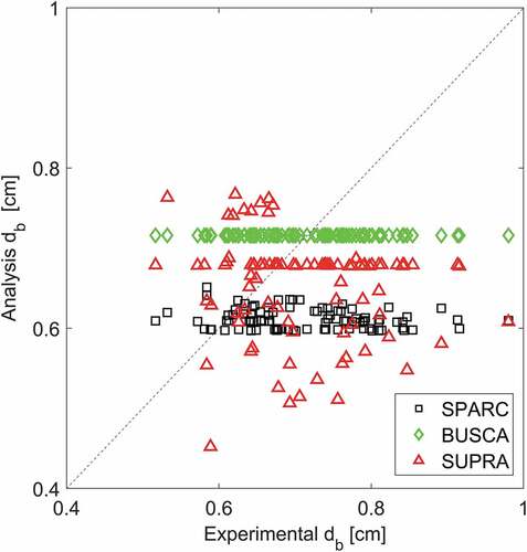
The bubble diameter obtained experimentally and calculated using correlation in the codes agrees fairly. Bubble size is mostly underpredicted by SPARC and SUPRA () models. Value of BUSCA model falls roughly in the range of experimental results. Bubble diameters in the experiments vary in a range of 0.0052–0.0118 m. Using correlations in the analysis codes described in [Citation2–Citation5], bubble diameter is 0.0060–0.0065 m from SPARC, 0.0072 m from BUSCA, and 0.0045–0.0077 m from SUPRA code. The experimental results are 0.85–1.97 (SPARC), 0.72–1.65 (BUSCA), and 0.70–1.73 (SUPRA) times greater than the analysis results (). In the pool scrubbing models, single bubble models are based on average bubble diameter, volume mean diameter or correlation. However, for experimental results reported in this paper, SMD is used to represent bubble diameter and corresponding bubble rising velocity. Furthermore, single bubble models used in analysis codes show weak dependency on the test conditions while the present experimental results show that SMD and bubble rising velocity have stronger dependency on the test conditions.
Table 1. Ratio of bubble parameters between experimental and analysis values.
Figure 17. Comparison of bubble diameters with models in pool scrubbing codes.
4.2.2. Bubble rising velocity
Experimental results of bubble rising velocity also fairly agree with pool scrubbing codes. Bubble rising velocity in the experiments varies in the range of 0.166–0.514 m/s, while from analysis codes it is 0.242–0.257 m/s (SPARC in ) and 0.241–0.248 m/s (BUSCA in and SUPRA in ). Since all analysis codes result in quite similar values, the experimental results are 0.66–2.06 (SPARC) and 0.69–2.07 (BUSCA and SUPRA) times greater than analysis results (). From the pool scrubbing point of view, a faster bubble needs shorter time to reach the pool surface. Thus, FPs aerosols have shorter time to reach the bubble surface so that FPs retention could become small. The discrepancies of bubble rising velocity between experiments and analysis code results have the same reason as for SMD.
Figure 18. Comparison of bubble rising velocity with models in pool scrubbing codes: (a) SPARC, (b) BUSCA, (c) SUPRA.
4.3. Bubble parameters effect on aerosol retention mechanisms
As discussed in Section 4.2, experimental and analysis results of bubble diameter and rising velocity show a discrepancy; hence, it results in a different evaluation of efficiency for pool scrubbing effect. For clarification on how separate retention mechanisms are affected by bubble size and bubble rise velocity, ratio of deposition velocities between experimental and analysis results was evaluated for each experimental case by EquationEquations (5)(5)
(5) –(Equation9
(9)
(9) ). Gravitational sedimentation velocity is not dependent on bubble parameters (see EquationEquation (5)
(5)
(5) ); thus, this mechanism is not affected. Other retention mechanisms are dependent on both bubble diameter and bubble rising velocity. Inertial impaction shows the highest sensitivity on bubble parameters (see ). Ratios of experimental and analysis results are 0.44–2.78 (SPARC), 0.53–3.36 (BUSCA), and 0.45–3.18 (SUPRA). Brownian diffusion and steam condensation deposition velocities have the same dependency on bubble parameters; therefore, the ratio of experimental and analysis results is the same: 0.72–1.19 (SPARC), 0.79–1.30 (BUSCA), 0.73–1.34 (SUPRA), if cv0-cvb is not affected by db and vb.
Table 2. Ratio of deposition velocities between experimental and analysis results.
FP retention efficiency (DF) is determined by each deposition velocity; hence, it is also important to evaluate the effect on DF. In order to evaluate which mechanism has the highest significance for DF evaluation (EquationEquation (10)(10)
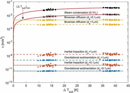
(10) ), the concrete value deposition velocities of each aerosol retention mechanism should be calculated. CsI of 1-μm size particles were taken as reference for FPs aerosol diameter (particle density 4.51 × 10⁻³ kg/m3, particle diffusion coefficient 2.75 × 10⁻¹¹ m2/s, slip correction factor 1.16 [Citation19]). The deposition velocity of gravitational sedimentation and inertial impaction turned out to be in the order of (1.8–2.2) × 10−10 m/s and (4.0–12) × 10−10 m/s, respectively (). The deposition velocity of Brownian diffusion was calculated to be in order of (2.7–4.5) × 10−5 m/s. Thus, considering this result, evaluating retention efficiency from the rising bubble, gravitational sedimentation, and inertial impaction can be neglected under experimental conditions.
Table 3. Deposition velocities (m/s) of separate retention mechanisms based on measured SMD and vb.
To evaluate steam condensation deposition velocity, steam mass concentration difference Δc was obtained by measuring the temperature of the forming bubble at downcomer outlet compared with pool water temperature as shown in . Thermocouple was attached approximately ~1 mm below D/C outlet. Average Δc between the downcomer outlet region and pool surface can be calculated as half difference between saturated steam density corresponding to D/C forming bubble and saturated steam density corresponding to pool water temperature close to D/C outlet assuming no temperature difference between bubble and S/P close to the pool surface. Condensation mainly takes place around the downcomer outlet, close to the pool surface Brownian diffusion dominantly occurs due to Δc = 0 in the region.
Figure 19. Measurement of bubble temperature at D/C outlet.
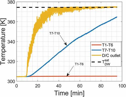
Measurement was started immediately before steam was supplied to D/W (in ). During D/W heat-up period, temperature at D/C outlet increased sharply and reached steady state at approximately 374 K, which was 3 K lower than the temperature in D/W (TD/W = 377 K). Δc was calculated using the lower envelope of measured temperature after a steady state was reached to evaluate bubble temperature immediately after bubble detachment. The result is shown in as a function of ΔTsub. With increasing pool temperature, steam condensation slows down and stops when saturation temperature is reached; hence, vv, as well as Δc, is 0 at ΔTsub = 0.
Figure 20. Average steam mass concentration difference in the bubble.
Applying obtained Δc for vv, vv turned out to be in the range of – (3.8–14.7) × 10−3 m/s as shown in . However, as mentioned before, steam condensation mainly takes place around downcomer outlet. For example, if steam condensation stops at 0.1Hs, vv becomes – (3.8–14.7) × 10−4 m/s. Even though steam condensation deposition velocity decreases 10 times, steam condensation still remains the dominant retention mechanisms compared with other retention mechanisms (). Deposition velocities of each retention mechanism were presented and compared in semi-log scale in . The result shows that steam condensation deposition velocity becomes smaller than Brownian diffusion deposition velocity when subcooling (ΔTsub)min = 0.75 K and this value increases to (ΔTsub)min = 0.758 K if steam condensation ceases at 0.1Hs from downcomer outlet (empty square markers in the graphs). Additionally, deposition velocities were calculated using CsI of 0.1 μm size particles as reference for FPs aerosol diameter so that particle diffusion coefficient becomes 6.67 × 10⁻¹⁰ m2/s, slip correction factor 2.81 [Citation19]. In this case, Brownian diffusion deposition velocity increased to (1.48–2.38) × 10−4 m/s; therefore, steam condensation deposition velocity becomes smaller than Brownian diffusion deposition velocity when subcooling is (ΔTsub)min = 0.37 K and (ΔTsub)min = 3.85 K if steam condensation ceases at 0.1Hs from downcomer outlet. This result suggests the release from Fukushima Daiichi NPP when prior to the W/W venting S/P temperature increased close to saturation, hence reducing the efficiency of FPs aerosol retention.
Figure 21. Comparison of deposition velocities' magnitudes based on measured SMD and vb.
Deposition velocities of gravitational sedimentation, inertial impaction, and Brownian diffusion are uniform throughout the pool from the outlet point to the pool surface according to EquationEquations (5)(5)
(5) –(Equation7
(7)
(7) ). Hence, measured SMD and corresponding vb could be directly used for validating the model of these mechanisms. As shown in , measured SMD and vb and analysis values have a fair agreement, so that also demonstrates fair agreement for vs, vd and vv. As for inertial impaction, even though ratios of vc vary in greater range than vd and vv, the order of vc is much smaller as given in . Hence, modelling of vs, vc, and vd used in pool scrubbing codes is appropriate under atmospheric pressure condition.
However, according to EquationEquations (9(9)
(9) ), Δc is not uniform. Besides, steam condensation is the dominant retention mechanism except for low subcooling conditions. Therefore, modelling of steam condensation retention mechanism should be further carefully examined.
5. Conclusion
The rising bubble hydrodynamics during W/W venting was investigated by a backlit shadowgraphy technique capturing the images with high-speed camera. Experimental results of bubble diameter represented by SMD and not only average bubble rising velocity but also bubble rising velocity corresponding to SMD are presented. SMD could be more appropriate than average bubble diameter, volume mean diameter or correlation used in pool scrubbing codes. However, SMD data for pool scrubbing were not available thus far. The effects of varied parameters (air content, submergence, D0, TS/P) on SMD and bubble rising velocity were investigated.
Air content had a small effect on SMD, while bubble rising velocity decreased with increasing air content. In the deeper submergence, bubble parameter became less scattered. With increasing S/P temperature, both SMD and bubble rising velocity were decreasing as dominant bubble break-up mechanism was due to reduced surface tension under higher S/P temperature. Thermal stratification did not have a significant effect on both SMD and bubble rising velocity as bubbles were rising through the higher temperature region only. Downcomer diameter did not affect SMD at the pool surface, while slight bubble rising velocity increase was observed.
Furthermore, bubble parameter effect on deposition velocity of aerosol retention mechanisms was investigated. Measured SMD and the corresponding vb have a fair agreement with the values adopted in the pool scrubbing codes; thus, calculated values of vs, vc and vd demonstrate fair agreement with those based on the measured data. Hence, modelling of vs, vc and vd used in pool scrubbing codes is appropriate under atmospheric pressure condition. Steam condensation is the dominant retention mechanisms except for low subcooling conditions. However, actual steam condensation driving force Δc is not uniform. Therefore, modelling of steam condensation retention mechanism should be further carefully examined.
In summary, the present database on SMD and bubble rising velocity and the physical explanation of varied parameters (air content, submergence, D0, TS/P) effect could be used for the update of pool scrubbing codes.
Nomenclature
| a | = | Major axis of ellipse [m] |
| b | = | Minor axis of ellipse [m] |
| BUSCA | = | BUbble SCrubbing Algorithm |
| Cm | = | Slip correction factor [-] |
| cv0 | = | Steam mass concentration at the bubble and pool water interface [kg/m3] |
| cvb | = | Bulk bubble steam mass concentration[kg/m3] |
| db | = | Bubble diameter [m] |
| dvm | = | Volume mean diameter [m] |
| D | = | Diffusion coefficient [m2/s] |
| D/C | = | Downcomer pipe |
| D/W | = | Drywell |
| D0 | = | D/C diameter [m] |
| Dp | = | FP particle size [m] |
| DvB | = | Molecular diffusivity of steam in non-condensable gas [m2/s] |
| DF | = | Decontamination factor [-] |
| DFb | = | Decontamination factor of FPs removal from the rising bubble [-] |
| DFi | = | Decontamination factor of FPs removal by initial impaction at the D/C outlet region [-] |
| DFs | = | Decontamination factor of FPs removal by initial steam condensation at the D/C outlet region [-] |
| FP | = | Fission product |
| g | = | Gravitational acceleration [m/s2] |
| Hs | = | Downcomer submergence [m] |
| min | = | FPs aerosol mass flowing into suppression pool [kg] |
| mout | = | FPs aerosol mass escaping from suppression pool [kg] |
| MW | = | Molecular water mass [kg/kmol] |
| NPP | = | Nuclear power plant |
| PCV | = | Primary containment vessel |
| Ps | = | Total pressure at the pool surface [Pa] |
| PW | = | Steam partial pressure inside the bubble [Pa] |
| R | = | Universal gas constant [J/(K∙kmol)] |
| RPV | = | Reactor pressure vessel |
| ReG | = | Reynolds number for carrier gas [-] |
| SMD | = | Sauter mean diameter [m] |
| SPARC | = | Suppression Pool Aerosol Removal Code |
| SUPRA | = | SUppression Pool Retention Analysis |
| S/P | = | Suppression pool |
| SB | = | Bubble surface area [m2] |
| TD/W | = | Drywell temperature [K] |
| TS/P | = | Pool water temperature [K] |
| VB | = | Bubble volume [m3] |
| vb | = | Bubble rising velocity [m/s] |
| vc | = | Deposition velocity of inertial impaction [m/s] |
| vd | = | Deposition velocity of Brownian diffusion [m/s] |
| vs | = | Deposition velocity of gravitational sedimentation [m/s] |
| vv | = | Deposition velocity of steam condensation/evaporation [m/s] |
| v0 | = | Exit velocity of gas mixture at downcomer outlet [m/s] |
| W/W | = | Wetwell |
| Wv | = | Average steam flux [kg/(m2∙s)] |
| xnc | = | Mole fraction of non-condensable gas in the gas mixture [-] |
Greek letters
| Δc | = | Steam mass concentration difference[kg/m3] |
| Δt | = | Time interval when the bubble is visible in the frame [s] |
| ΔTsub | = | Subcooling temperature [K] |
| Δx | = | Bubble travelling distance [m] |
| σ | = | Liquid surface tension [N/m] |
| ρ | = | Liquid density [kg/m3] |
| ρp | = | Particle density [kg/m3] |
| ηb | = | Gas viscosity [Pa∙s] |
| θ | = | Angle between the direction of the circulating gas flow in the bubble and the vertical axis [°] |
Acknowledgments
This work was supported (or supported in part) by a scholarship award to the author from the College Women’s Association of Japan.
Disclosure statement
No potential conflict of interest was reported by the authors.
References
- The Tokyo Electric Power Company Inc. The 4th progress report in the investigation and examination of unconfirmed and unresolved issues on the development mechanisms of the Fukushima Daiichi Nuclear Accident. Tokyo, Japan:Tokyo Electric Power Company, Inc; 2015. (Progress Report No. 4).
- Wassel AT. Analysis of radionuclide retention in water pools. Nucl Eng Des. 1985;90:87–104.
- Ramsdale S, Guntay S, Friederichs H. BUSCA-JUN91 reference manual. Zurich, Switzerland: Paul Scherrer Institut; 1995. ( PSI Bericht: Nr. 95-05).
- Owczarski PC, Burk KW SPARC-90: A code for calculating fission product capture in suppression pool. Richland, WA: Pacific Northwest Laboratory; 1991. (NUREG/CR–5765).
- Owczarski PC, Schreck RI, Postma AK Technical bases and user’s manual for the prototype of a suppression pool aerosol removal code (SPARC). Richland, WA: Pacific Northwest Laboratory; 1985. (NUREG/CR–3317).
- Hakii J, Kaneko I, Fukusawa M, et al. Experimental study on aerosol removal efficiency for pool scrubbing under high temperature steam atmosphere. Proceeding of the 21st DOE-NRC Nuclear air cleaning conference; 1990 Aug 13-16; San Diego, CA.
- Kulhman MR, Giesele JA, Merilo M, et al. Scrubbing of fission product aerosol in LWR water pool under severe accident conditions. Proceeding of an international symposium on source term evaluation for accident conditions; 1985 Oct 28-Nov 1, Columbus, OH.
- Marcos Crespo MJ, Gomez Moreno FJ, Melches Serrano I, et al. Lace-Espana experimental programme on the retention of aerosols in water pools. Madrid, Spain: CIEMAT; 1994. ( Ciemat; 740).
- Herranz LE, Escuderi MJ, Peyres V, et al. Review and assessment of pool scrubbing models. Madrid, Spain: CIEMAT; 1996. ( Ciemat; 784).
- Hotta A, Akiba M, Hoshi H, et al. Current severe accident research activities in S/NRA/R Japan. Presented at: IAEA Training Meeting in Post-Fukushima Research and Development Strategies and Priorities; 2015 Dec 15-18; Vienna, Austria.
- Berna C Estimation of the radioactive aerosols capture in accidental sequences on nuclear power plants [dissertation]. Valencia, Spain: Universitat Politecnica de Valencia; 2017.
- Yamamoto K, Narushima Y, Miyazaki, et al. Bubble dynamics with aerosol in swarm flow during pool scrubbing. NTHAS10: The Tenth Korea-Japan Symposium on Nuclear Thermal Hydraulics and Safety; 2016 Nov 27-30; Kyoto, Japan.
- Fujiwara K, Abe Y, Kaneko A, et al. The behavior of aerosol particle inside a rising bubble during pool scrubbing. Proceedings of the 2017 25th International Conference on Nuclear Engineering ICONE25; 2017 Jul 2-6; Shanghai, China.
- Abe Y, Fujiwara K, Saito S, et al. Bubble dynamics with aerosol during pool scrubbing. Nucl Eng Des. 2018;337:96–107.
- Hamasaki R. Shibia akushidentoji no kakunou youkinai no genjitsuteki sousuta-mu hyouka [Evaluation of realistic source term in PCV during a severe accident]. Tokyo, Japan: Atomic Energy Society of Japan; 2010. ( Japanese).
- Sotiriadis AA, Thorpe RB, Smith JM. Bubble size and mass transfer characteristics of sparged downwards two-phase flow. Chem Eng Sci. 2005;60:5917–5929.
- Kowalczul PB, Drzymala J. Physical meaning of the Sauter mean diameter of spherical particulate matter. Particul Sci Technol. 2016;34(6):645–647.
- Rohsenow WM, Choi HY. Heat, mass and momentum transfer. Upper Saddle River (NJ): Prentice Hall; 1961.
- Takahashi K. Earozorugaku no kiso [Basics of Aerosol science]. Kyoto: Japan Association of Aerosol Science and Technology; 2003. ( Japanese).