 ?Mathematical formulae have been encoded as MathML and are displayed in this HTML version using MathJax in order to improve their display. Uncheck the box to turn MathJax off. This feature requires Javascript. Click on a formula to zoom.
ABSTRACT
An effective dose calculation method is important in the design of efficient shields in radiation facilities. Some analytical methods have been shown to provide a simple and quick design analysis; however, no suitable method exists that can be applied to a room located directly under an X-ray irradiation room. We propose a new analytical method that uses the multiple reflection ratio predetermined by a Monte Carlo simulation and the differential dose albedo given by the Chilton–Huddleston semi-empirical equation. Our method is verified by comparison with the Monte Carlo simulation, performed for the case of an electron linac facility with an accelerated energy of 10 MeV, where the shielding floor has a thickness of 1.6–2.0 m and the downstairs room has a height of 0.5–1.5 m. The difference between the effective X-ray doses in the downstairs room calculated via the proposed analytical method and the Monte Carlo simulation is less than 25% when the horizontal distance from the X-ray beam to the evaluation point exceeds 3 m and the evaluation point is set at half of the height of the room. The new analytical method can be efficiently and accurately applied to the calculation of the effective dose.
1. Introduction
The development of effective dose calculation methods is important for the design of shielding in radiation facilities used to prevent public exposure to radiation that might leak from the radiation-controlled area. Numerous analytical methods have already been developed for maze streaming, duct streaming, and radiation transmission through a shielding wall [Citation1–Citation4]. However, in cases of a complicated shielding design that does not fall into their range of application, these methods may give results that overestimate or underestimate real values. In radiation shielding design, underestimation must be avoided to prevent public exposure, whereas overestimation leads to a higher building cost for the facility. Monte Carlo simulations such as those performed using the Monte Carlo N-Particle Transport Code (MCNP code) [Citation5] can provide results with better accuracy; however, they require a significantly larger amount of time and skill than the analytical methods.
In this study, we present a new analytical method we have developed to determine the values for X-rays transmitted through a shielding wall and scattered in a narrow space after transmission. Our method is particularly effective when the evaluation points are positioned in a room located directly under an X-ray irradiation room, as is the case for rooms used for a seismic base isolation structure that supports special equipment, such as seismic isolation rubbers or oil dampers. Oishi et al. have investigated such evaluation points by experimental measurements and a Monte Carlo simulation [Citation6]. The International Atomic Energy Agency (IAEA) provides an analytical method for the path X-rays take when they are transmitted through a maze wall and scattered toward the entrance of the irradiation room; however, this method is not entirely applicable for the evaluation points in a downstairs room because it does not consider multiple reflections that may occur in the narrow space, and the data of the differential dose albedo for the X-rays are insufficient for shallow angle scattering. Our newly developed method considers the effect of scattering in the shielding wall, as well as the multiple reflections on the surfaces in the narrow space. In addition, the differential dose albedo for an arbitrary angle is obtained using the Chilton–Huddleston semi-empirical equation [Citation4,Citation7].
To verify and validate our method, we calculated the effective doses in the room underneath the X-ray irradiation room. The bremsstrahlung X-rays generated by an electron linac with the 10 MeV energy which is the most commonly used system for radiotherapy in Japan was used as an X-ray source of the calculation model. The results of our new method were evaluated by a comparison with the MCNP5 simulation and the IAEA analytical method.
2. Calculation method
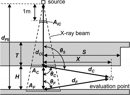
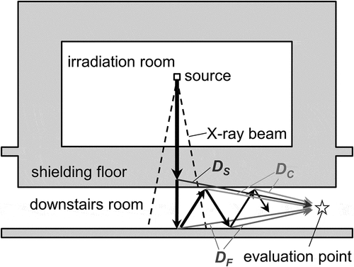
The X-ray paths from the source to an evaluation point in the room underneath the X-ray irradiation room are categorized, as shown in . Henceforth, the room underneath the irradiation room will be referred to as the room downstairs. DS denotes the dose component scattered only in the shielding floor of the irradiation room, DF is the dose component transmitted through the shielding floor and finally reflected on the floor of the downstairs room, and DC is the dose component transmitted through the shielding floor and finally reflected on the ceiling of the downstairs room. The components DF and DC contain the multiple reflections in the downstairs room. When more complex paths and the other effects such as neutron capture gamma rays from neutrons produced by photonuclear reactions can be ignored, the total effective dose, D, is given by
Figure 1. X-ray paths for the new analytical method. The arrows indicate simplified examples of X-ray paths. Some X-rays actually include the paths scattered or reflected in the direction opposite to that toward the evaluation point on the way.
2.1. Scattered dose component in the shielding floor
Scattering in the shielding floor is assumed to be replaceable with the scattering on the ceiling surface of the downstairs room. Then, DS can be calculated as
where W [Gyh−1] is the workload or the dose rate at a distance of 1 m from the source, B represents the transmission factor of the X-ray beam through the shielding floor, calculated using the tenth value layer of the shielding material and the shielding thickness, F is the conversion factor from Gy to Sv, U is the utilization factor for the beam directed at the shielding floor, AC [m2] is the irradiation field size projected to the ceiling surface of the downstairs room, αS(θS) is the reflection coefficientFootnote1 from the center of the ceiling surface of the downstairs room to the evaluation point with an angle θS, dC0 [m] is the distance from the source to the ceiling surface of the downstairs room, and dC [m] is the distance from the ceiling surface of the downstairs room to the evaluation point. schematically shows the quantities used in EquationEquation (2)(2)
(2) . If the irradiation field is of a size AIC at isocenter or at a distance of 1 m from the source, where AC/dC02 = AIC, then EquationEquation (2)
(2)
(2) can be modified as
2.2. Scattered dose component on the floor of the downstairs room
In the first step, the calculation of the effective dose obtained due to the X-rays that are transmitted through the shielding floor and reflected once on the floor of the downstairs room is performed similarly to the EquationEquations (2)(2)
(2) and (Equation3
(3)
(3) ), such that
In EquationEquation (4)(4)
(4) , DF1 represents the effective dose rate at the evaluation point, AF is the irradiation field size projected to the floor surface of the downstairs room, αF(θS) is the reflection coefficient from the center of the floor surface of the downstairs room to the evaluation point with the angle θF, dF0 is the distance from the source to the floor surface of the downstairs room, and dF is the distance from the floor surface of the downstairs room to the evaluation point. The IAEA method of calculation for scattering X-rays after transmission through a maze wall is the same equation in the case when F = 1.
Then, the reflection ratio of the X-rays from the floor to the ceiling and from the ceiling to the floor of the downstairs room is defined as r. If r, F, and αF are constant regardless of the energy reduction due to reflection, the effective dose reflected on the floor after a double reflection in the downstairs room is equal to r2DF1 and it is equal to r4DF1 after four reflections. The total effective dose from the floor is expressed using a sum of an infinite geometric series:
2.3. Scattered dose component on the ceiling of the downstairs room
An effective dose due to the X-rays transmitted through the shielding floor and scattered once on the ceiling of the downstairs room after scattering once on the floor is equal to
where DC1 is the effective dose rate at the evaluation point and αC(θC) is the reflection coefficient from the center of the ceiling surface of the downstairs room to the evaluation point with angle θC. The total effective dose from the ceiling after multiple reflections in the downstairs room is expressed like in EquationEquation (5)(5)
(5) , as follows:
Furthermore, if the evaluation point is located at one half of the height of the downstairs room, dC and αC are equal to dF and αF, respectively. Then, r is given by
where DC’ and DF’ are equal to DC and DF at one half of the height of the downstairs room, respectively. Therefore, r can be calculated using the Monte Carlo simulation described further in the text.
2.4. Chilton–Huddleston semi-empirical equation of dose albedo
The reflection angles from the surfaces of the downstairs room to the evaluating point take values close to 90°, whereas the results of IAEA present a table of reflection coefficients up to 75° [Citation1]. To calculate the reflection coefficient for any reflection angle, the differential dose albedo is calculated by the Chilton–Huddleston semi-empirical equation. The differential dose albedo, α, for a normal incidence of X-rays with an energy of E0 and the reflection angle θ is given by
and
where C and C’ take the constant values shown in and r0 is the classical electron radius. To avoid a negative value of α when the reflection angle exceeds 90°, such as θS in , the absolute value of α is used in EquationEquation (9)(9)
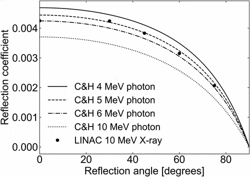
(9) . shows the differential dose albedos for reflection angles between of 0° and 90°, to normal incidence on concrete. The lines in the figure show the albedo values for monoenergetic photons with an energy of 4 MeV, 5 MeV, 6 MeV, and 10 MeV, whereas the dots show the reported value at a 10 MeV linac by IAEA [Citation1]. The differential dose albedo for X-rays of 5 MeV from the concrete surface is in good agreement with the reported value of the linac, except when the reflection angle is 0°. This result aligns with that obtained by McGinley [Citation3], i.e. the reflection coefficient at the first reflection is based on one half of the electron accelerating energy.
Table 1. Constants of the Chilton–Huddleston semi-empirical equation for reflection on concrete [Citation7].
3. Reflection coefficient verification using a Monte Carlo simulation
3.1. Calculation model
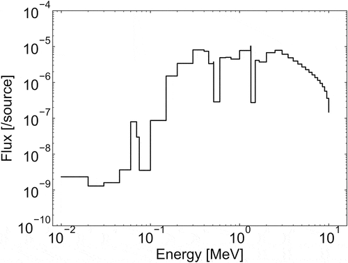
A medical facility with an electron linac system with an accelerated energy of 10 MeV was used as the calculation model. The source was set at a height of 2.295 m from the floor of the irradiation room. The X-rays were irradiated in a cone shape, the irradiation field was of the size of 0.16 m2, and the workload at the isocenter was equal to 360 Gyh−1. The shielding floor of the linac room is constructed using concrete with a thickness (T) of 1.8 m and a density of 2.1 gcm−3. The height of the downstairs room (H) is equal to 1.0 m and its floor material is also concrete with 30 cm thick. The MCNP5 code was used for Monte Carlo simulation. The spectrum of the X-ray source shown in is bremsstrahlung X-rays generated by irradiating electrons of an energy of 10 MeV on a copper target with a thickness of 15 mm. This spectrum is calculated first, by using the MCNP5 code, and the results are tallied at 1 m from the target. The effective doses in the downstairs room are calculated using point tallies set at every 1 m in the horizontal direction (X), from 1 m to 9 m. In the newly developed analytical method, the transmission B is calculated as follows [Citation1]:
where t is the shielding thickness, and T1/10 is the tenth value layer of the shielding material, equal to 435 mm for X-rays of 10 MeV linac against ordinary concrete with a density of 2.1 gcm−3 which calculated in proportion to the density from the T1/10 of 389 mm against the density of 2.35 gcm−3 [Citation1]. In addition, F and U are constants with the value of 1 and the conversion factors of the effective dose from the photon flux can be found in [Citation8].
presents the calculation models (a), (b), and (c). In model (a), DS is calculated by ignoring the reflection on the floor of downstairs room. In model (b), DS + DC is calculated by setting virtual hemispheres around the point tallies that completely shield the X-rays reflected from the floor. In model (c), DF is calculated by also setting the virtual hemispheres around the tallies to shield the X-rays from the ceiling of the downstairs room. The corresponding values of DCs are calculated by subtracting the results of model (a) from those of model (b).
3.2. Results
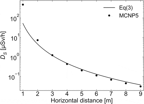
shows the effective doses DS at 0.5 m from the ceiling of the downstairs room calculated by the MCNP5 using model (a) and the analytical method represented by EquationEquation (3)(3)
(3) . The EquationEquation (3)
(3)
(3) for DS involving differential dose albedo αS calculated by EquationEquation (9)
(9)
(9) with forward scattering or reflection angle exceeding 90° shows a good agreement with the results of the MCNP5, except in the area less than 2 m in the horizontal direction or near the irradiation field where the X-ray beam reaches directly.
Figure 6. Comparison of DS calculated using EquationEquation (3)(3)
(3) and the MCNP5 code in model (a).
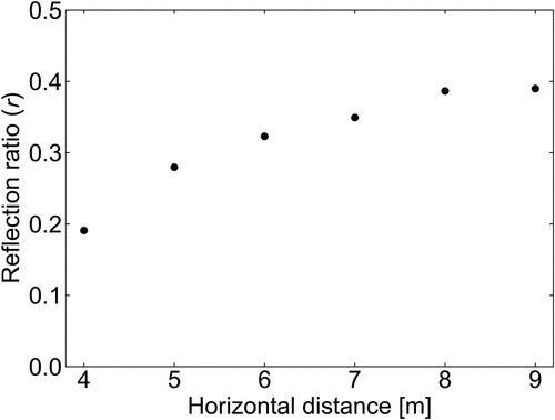
The reflection ratio r in the downstairs room was calculated as shown in EquationEquation (8)(8)
(8) and plotted in as a function of horizontal distance. The reflection ratio has a tendency to increase with an increase in the distance, saturating at about 0.4. As the ratio increases, it becomes safer calculation; therefore, the reflection ratio of 0.4 is appropriate in the model. In this case, the effective dose, D, in the downstairs room is calculated using by inputting EquationEquations (3)
(3)
(3) , (Equation5
(5)
(5) ), and (Equation7
(7)
(7) ) into EquationEquation (1)
(1)
(1) , as follows:
Figure 7. Reflection ratio in the downstairs room calculated using EquationEquation (8)(8)
(8) .
If the evaluation point is located at half of the height of the downstairs room, EquationEquation (12)(12)
(12) can be modified as
where, d = dC = dF and α = αC = αF.
4. Validation of the new analytical method
4.1. Calculation models
The linac facility model was investigated with a focus on the shielding floor thickness (T) of 1.6 m, 1.8 m, and 2.0 m, the floor width (S) of 5 m, 6 m, and 7 m, and the height of the downstairs room (H) equal to 0.5 m, 1.0 m, and 1.5 m. The X-ray source and shielding material were the same as in the model discussed in Section 3.1. In addition, both models of a special structure on the floor were also investigated, as shown in . Model (a) has a 30 cm recess on the shielding floor with an iron plate that is 1.5 cm thick, whereas model (b) has the recess and an iron plate in the shielding floor that is 20 cm thick. The values of T1/10 for X-rays of the energy of 10 MeV against iron [Citation1] were equal to 105 mm.
Figure 8. Models that consider a special structure of the shielding floor. (a) A recess with a depth of 30 cm and an iron plate of a thickness of 1.5 cm. (b) A recess with a depth of 30 cm and an iron plate of a thickness of 20 cm in the shielding floor.
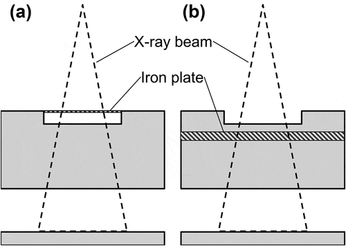
The effective doses in the downstairs room were calculated using a Monte Carlo simulation and the newly developed analytical method. In addition, for comparison, the IAEA method was also calculated using the differential dose albedo to an arbitrary reflection angle of EquationEquation (9)(9)
(9) .
4.2. Results
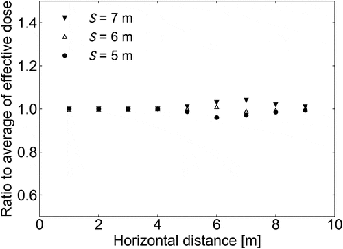
To verify the influence of the size of the shielding floor area on multiple reflection, the effective doses were compared when the variables of the model were set to T = 1.8 m, H = 1.0 m, and S was equal to 5 m, 6 m, or 7 m, as shown in , with an area of 100 m2, 144 m2, and 196 m2, respectively. However, no significant difference was discovered in the effective dose by confirmation of each deviation based on the average value. The ratios of the effective doses when S is equal to 5 m, 6 m, or 7 m to the average value can be seen in . The deviation from the average value is negligibly small at evaluation points at a distance of less than 5 m from X-ray beam axis, and even when the effective doses were the highest, at S = 7 m, the deviation from the average value was less than 5%. The following results were fixed to S = 7 m.
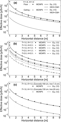
shows a comparison of the results of the analytical method and the MCNP5 simulation. ) shows the effective doses both at 1 cm from the ceiling surface and from the floor surface of the downstairs room when T = 1.8 m and H = 1.0 m. The results of the MCNP5 simulation show that the effective doses at the floor surface were higher than those at the ceiling surface. The new analytical method was in good agreement with the results of the MCNP5 simulation, within 18% on the floor side and within 28% on the ceiling side, where the horizontal distance of the evaluation points exceeds 3 m. Since the X-rays are treated to be reflected only from the floor, the results at the floor surface calculated by the IAEA method are underestimated. The increase in error at 3 m or less is probably due to directly transmitted X-rays. The following focuses on evaluation points where the horizontal distance exceeds 3 m. The effective doses at the half-height of the downstairs room depend on T and H, and they are shown in ). The best obtained result was within 5% of the difference of the effective dose between the newly developed analytical method and the MCNP5 simulation when the model variables were set to T = 1.6 m and H = 1.5 m, whereas the worst was within 25%, when the variables were set to T = 2.0 m and H = 0.5 m. Moreover, ) shows the effective doses at the half-height of the downstairs room in the model with T = 1.8 m and H = 1.0 m, with the special floor structure shown in . Each result of the newly developed analytical method was in good agreement with the result of the MCNP5 simulation, within 12%. As a result of validation, the difference in the effective dose calculated by the new analytical method and the MCNP5 simulation in the case of the evaluation point being set near the ceiling surface was 28%, whereas the others were 25% or less.
5. Discussion
The results of our newly developed analytical method show good agreement with the results of the Monte Carlo simulation, even when the evaluation points are set far away from the shielding floor and the shielding floor has a complex structure, e.g. if it includes an iron plate. It has also been shown that the new analytical method can be applied to an arbitrary height of the downstairs room and the method can be used to calculate the effective dose in the downstairs room accurately and speedily. However, it should be noted that the error increases in the vicinity of the X-ray irradiation field.
In case of a medical linac system, the effective dose in the downstairs room by a leakage X-ray from the linac head, which is suppressed less than 1/1000 of an X-ray beam, should be evaluated. An analytical method for simple X-ray transmission is detailed in [Citation1–Citation4]. However, it can be small enough if the thickness of the shielding floor is made sufficiently large to shield X-ray beam.
In this study, the new analytical method was applied to the height of the downstairs room between 0.5 m and 1.5 m; however, further research is necessary to evaluate its accuracy for an increase in the applicable range of the height. In addition, the reflecting ratio in the downstairs room needs to be investigated in case of X-rays with a different energy. For X-rays with higher energy, the influence of neutrons due to photonuclear reactions cannot be neglected.
6. Conclusion
The new analytical method for the effective dose in the room underneath the linac room was proposed and validated. In this method, the multiple reflection ratio of X-rays in the downstairs room is predetermined by a Monte Carlo simulation and the differential dose albedo from the ceiling or the floor surface of the downstairs room to the evaluation point is calculated using the Chilton–Huddleston semi-empirical equation. In case of the linac system with an energy of 10 MeV, the reflection ratio in the downstairs room with the concrete floor and ceiling was found to be 0.4, and the energy of the incident X-rays for Chilton–Huddleston semi-empirical equation was found to be 5 MeV.
The results of the new analytical method were in good agreement with the results of Monte Carlo simulation, within 25% when the evaluation points were located at the half-height of the downstairs room and the horizontal distance from the X-ray beam to the evaluation points exceeded 3 m. The width of the shielding floor did not significantly influence the effective dose in the downstairs room. In this study, because the X-ray energy was up to 10 MeV, the effects of neutrons generated by photonuclear reactions could be neglected; however, their effect should be considered in the case of a linac system with higher energy.
Disclosure Statement
No potential conflict of interest was reported by the authors.
Notes
1. Reflection coefficient has the same meaning of the differential dose albedo.
References
- IAEA. Radiation protection in the design of radiotherapy facilities. Safety Reports Series No. 47. Vienna (Austria): IAEA; 2006.
- National Council on Radiation Protection and Measurements. Structural shielding design and evaluation for megavoltage x- and gamma-ray radiotherapy facilities. NCRP Report No. 151. Bethesda, MD (USA): National Council on Radiation Protection and Measurements; 2005.
- McGinley PH. Shielding techniques for radiation oncology facilities. Madison, WI (USA): Medical Physics; 2002.
- Nuclear Safety Technology Center. Practical manual on shielding calculation of radiation facilities 2015. Tokyo (Japan): Nuclear Safety Technology Center; 2015. [in Japanese].
- X-5 Monte Carlo Tem. MCNP – a general Monte Carlo N-particle transport code. Version 5 (LA-UR-03-1987). Los Alamos, NM (USA): Los Alamos National Laboratory; 2003.
- Oishi K, Kosako K, Nakamura T. Optimum shielding design for electron linac oncology facilities incorporating seismic base-isolation structure. Shielding Aspects of Accelerators, Targets and Irradiation Facilities – SATIF-10 Workshop Proceedings; 2010 June 2–4; Geneva, Switzerland.
- Chilton AB, Huddleston CM. A semiempirical formula for differential dose albedo for gamma rays on concrete. J Nucl Sci Eng. 1963;17:419–424.
- Radiation dose conversion coefficients for radiation shielding calculation: 2010 (AESJ-SC-R002:2010). Tokyo (Japan): Japan Atomic Energy Agency; 2010. [in Japanese].

