
 ?Mathematical formulae have been encoded as MathML and are displayed in this HTML version using MathJax in order to improve their display. Uncheck the box to turn MathJax off. This feature requires Javascript. Click on a formula to zoom.
ABSTRACT
Governing the rate of heat transport by condenser tubes in the passive containment cooling system (PCCS), the steam condensation over a vertical cylinder in the presence of air was investigated experimentally. The main objective of this study was to explore if the condensation heat transfer coefficient relies on the tube dimension, which has been a variable missed in most condensation models or has been embraced without experimental demonstration under phase change environments. The mean heat transfer coefficient was measured in the condensation test facility named JERICHO (JNU Experimental Rig for Investigation of Condensation Heat transfer On tube). The outer diameter of the condenser tube used in this study was set to 21.5 mm. The measured heat transfer coefficients were compared to those obtained from the 40-mm-O.D. tube, and a multiplier to correct the variation of the heat transfer coefficient with the tube diameter was proposed for its application to Lee correlation. The proposed correlation was further validated against another set of experimental data obtained from a separate test facility housing the 31.8-mm-O.D. tube.
1. Introduction
A passive cooling of the containment has emerged as a salient engineering strategy to enhance the safety of Gen III+ light water reactors and secure their own international competitiveness. The passive containment cooling system aims in general at achieving an assured protection of the containment integrity by means of steam condensation [Citation1,Citation2]. Lead by the state-run operator KHNP (Korea Hydro and Nuclear Power Co Ltd), the Korean design of the PCCS has recently been under development for installation in advanced reactors such as APR+ and iPOWER [Citation3,Citation4]. This was proposed to replace the conventional containment spray system which becomes out of order during a power outage.
illustrates the system configuration of the Korean PCCS [Citation3]; it consists of heat exchanger assemblies housing a number of vertical cylindrical tubes placed inside the containment building. Once the pressure boundary of the reactor coolant system (RCS) or the main steam line is broken, the released steam will be mixed with air to form a gaseous mixture, and condensed on the outer surface of condenser tubes. Thus, the decay heat from the core can be transported to the ultimate heat sink, a large-sized water pool in general, outside of the containment through a naturally driven flow of cooling water. Since a noncondensable gas degrades severely the rate of heat transfer by steam condensation, the overall thermal resistance around a condenser tube is dominated by the heat transfer coefficient on the exterior surface in contact with the air-steam mixture.
Figure 1. A system configuration of the PCCS to be deployed inside the containment of iPOWER [Citation3].
![Figure 1. A system configuration of the PCCS to be deployed inside the containment of iPOWER [Citation3].](/cms/asset/116d75b3-8c58-4cd9-a47a-2662d0efbc45/tnst_a_1736200_f0001_b.gif)
Motivated by heat transfer issues of the PCCS, extensive research has been conducted to measure the heat flux or heat transfer coefficient, either locally or globally, on a vertical cylinder in the presence of a noncondensable gas. In particular, a wide variety of recent experimental programs was undertaken by Korean universities and research institutes [Citation5–Citation9]. In the early phase of their studies, the design specifications of the PCCS were not fixed. Thus, in the precedent research, for example, such as a test campaign performed by JNU (Jeju National Univeristy) [Citation5], the provisional tube dimension was set to 40 mm in outer diameter referring to the design of the CHRS (containment heat removal system) in AES-2006. However, design parameters of the Korean PCCS were determined recently such that the condenser tube is 31.8 mm in outer diameter and 6.0 m in length [Citation10].
As shown in , the previous study by Lee et al. [Citation11] revealed that Lee correlation [Citation5] overestimated substantially the condensation heat transfer coefficient on a small diameter tube, such as the 12-mm-O.D. tube employed in TIT (Tokyo Institute of Technology) tests [Citation12]. The large deviation resulted from the fact that Lee correlation was deduced from test data obtained from condenser tube of nearly 40 mm in outer diameter. This implies that applying the separate effect test data from the condenser tube having a different diameter from the prototype give rise to an erroneous prediction on the heat removal capability, and thus an experimental evidence against the effect of tube dimensions is required. Note that the mechanistic condensation model embedded in commercial thermal-hydraulic codes such as RELAP5 or GOTHIC do not take into account such an effect [Citation13,Citation14]. Even though some previous studies employed the approximate correlation proposed by Popiel [Citation15] as the correction factor for the tube diameter, its validity has not been assessed yet for condensation environment in the presence of a noncondensable gas.
Figure 2. Comparison of heat transfer coefficients predicted by the empirical correlation of Lee et al. to those measured in the tests at MIT (38-mm-O.D. tube) and TIT (12-mm-O.D. tube) [Citation12].
![Figure 2. Comparison of heat transfer coefficients predicted by the empirical correlation of Lee et al. to those measured in the tests at MIT (38-mm-O.D. tube) and TIT (12-mm-O.D. tube) [Citation12].](/cms/asset/337f9135-463a-4f2f-8277-6e4adf59590a/tnst_a_1736200_f0002_oc.jpg)
As a study to explore the effect of the tube diameter on the air-steam condensation, Jeon et al. performed a parametric study, through a series of condensation experiments, by fabricating two condenser tubes with different outer diameters: 49.1 mm and 26.8 mm [Citation6]. It was reported that, depending on the air content in the mixture, the heat transfer coefficient increased by up to 20% for the smaller diameter tube. However, the number of obtained test data was not enough to figure out the dependence of the relative change in the heat transfer coefficient on gas mixture conditions, and develop a credible correction factor of the curvature effect.
This experimental study was conducted to measure the condensation heat transfer coefficient on a smaller diameter tube than the 40-mm-O.D. tube as used in the previous study, and elucidate how the tube dimensions affect the thermal performance of a condenser tube. The 21.5-mm-O.D. tube was fabricated and mounted on the JERICHO facility in JNU so that the experimental results can cover not only the tube dimension of the iPOWER PCCS but other design values eligible for a PCCS by establishing a consolidated database with those from Lee et al. [Citation5]. In the tests, the pressure varied from 2 to 5 bar, the air mass fraction from 0.10 to 0.81, the wall subcooling degree from 20 to 65 K. The measured heat transfer coefficients were compared to those obtained from 40-mm-O.D. tube by Lee et al., and a multiplier to account for the variation of the heat transfer coefficient with the tube diameter was proposed for its application to Lee correlation.
2. Experimental apparatus and test conditions
2.1. Description of JERICHO
A detailed description of the experimental apparatus and the measurement, and data reduction used for this investigation can be found in [Citation5]. The schematic diagram of the JERICHO facility is drawn in . The test vessel is a cylindrical stainless steel tank, which is 1950 mm high and 609 mm in diameter, to confine the air-steam mixture and to simulate the thermal conditions inside the containment building. Placed along the centerline of the test vessel is the condenser tube made from type 304L stainless steel. In order to facilitate the replacement of the condenser tube, the test vessel has been designed to equip with a large rectangular flange assembled to its side wall. Therefore, when replacing the condenser tube with another, one detaches the whole flange assembly from the test vessel, and in turn, disassembles the condenser tube from the connected pipelines which are thermally insulated.
Figure 3. Schematic diagram of the JERICHO facility in Jeju National University.
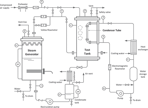
The boiler generates the steam by the submerged heaters and supplies it to the lower section of the test vessel through pipelines placed on opposite sides. Serving as a noncondensable gas in this study, air is provided at the top of the test vessel from a compressor. Cooling water is circulated into the condenser tube to adjust the surface temperature of the condensing wall. The rate of heat transport through the condenser tube is estimated via measurement of the temperature rise of cooling water across the effective heat transfer region. In the tests, the flow rate of cooling water was regulated so that the temperature rise lies within 5– 10 K; when this is too small, the measurement uncertainty increase in estimating the rate of heat removal, whereas a remarkable axial variation in the wall temperature will occur with a large temperature rise of cooling water.
The condenser tube used in this experiment is 1.0 m in length and 21.5 mm in outer diameter. The tube thickness is 5.0 mm; it has been designed to have a thick wall to lower errors in the measurements of inner and outer surface temperatures and thus obtain a more accurate estimate of the local heat flux. illustrates the location of thermocouples installed at the condenser tube for temperature measurement of inner/outer walls and cooling water. A pair of thermocouples to measure the surface temperatures and the local heat flux were installed at six measurement elevations, with a reduced spacing for upper three ones as the vapor-gas boundary layer begin to develop from the top. Grounded 1.0-mm-O.D. K-type thermocouples were used, and silver soldered into drilled holes. At each elevation, using the depths of the paired holes known a priori, the real surface temperatures are found by the correction equations as described in [Citation5].
Figure 4. Measurement locations of wall and coolant temperatures for the condenser tube used in the JERICHO tests.
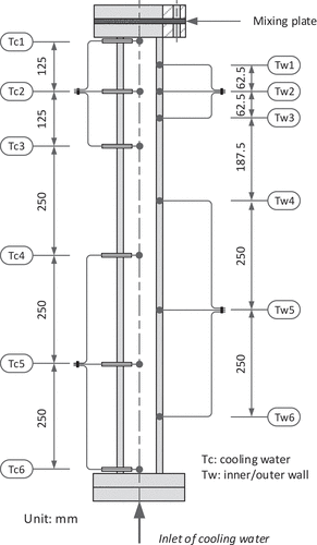
The axial variation of the coolant temperature inside the condenser tube is also measured by ungrounded 1.0-mm-O.D. K-type thermocouples. They were positioned at 0, 125, 250, 500, 750, and 1000 mm from the top of the condenser tube by penetrating horizontally through the condenser tube wall. Note that the value indicated by these thermocouple is the local coolant temperature. As cooling water is side heated, the thermal boundary layer develops and a steep temperature gradient will be established in the vicinity of the inner wall of the condenser tube. Thus, the fluid temperature measured at the thermocouple tip positioned centrally in the channel indicates, actually, the lowest temperature across the cross-section, not the bulk temperature. To resolve this issue, a perforated plate was inserted at the outlet section so that it could promote the mixing of the fluid. Then, the bulk temperature at the exit is determined as the arithmetic mean of temperatures measured by two additional thermocouples installed immediate downstream of the perforated plate.
2.2. Test conditions
The experimental conditions of condensation tests are basically similar to those of the previous study using the 40-mm-O.D. tube. The test matrix of this study is shown in . The first set of test runs was conducted varying the air content in the gaseous mixture at isobaric conditions while maintaining the wall subcooling degree, which is defined as the difference between the gas temperature in the bulk (assumed equal to saturation temperature in this work) and the mean wall temperature, to around 40 K. This enables to quantify the changes in the condensation heat transfer coefficient by the tube dimensions through comparison to the measured data from ‘Program 1ʹ in the tests of Lee et al. [Citation5].
Table 1. Test matrix of the condensation tests for the 21.5-mm-O.D. tube.
In the second set, only the wall subcooling degree was changed at a fixed bulk condition. The tests were conducted at 2 and 4 bar with atmospheric air present while the wall subcooling degree was varied from 20 to 65 K. The last set was intended to collect sufficient data covering a wide range of test conditions, without adjusting the wall temperature of the condenser tube to a prescribed value. The reader is referred to [Citation5] for a comprehensive description of test procedures and data reduction.
3. Experimental results
3.1. Uncertainty analysis
The global heat transfer coefficient over the condenser tube was obtained based on the coolant energy balance. Using an estimate of heat flow across the tube calculated from the rise in cooling water temperature, one can obtain the average condensation heat transfer coefficient as:
It is noted that axially averaged values of the bulk temperature and the outer wall temperature were used in calculating the mean heat transfer coefficient. Then, the uncertainty of the condensation heat transfer coefficient is calculated as following:
where
The measurement uncertainties of instruments used in the tests are same as those summarized in [Citation5]. As a result, an average uncertainty of the condensation heat transfer coefficients obtained from the tests was estimated to be 13.4% for the 21.5-mm-O.D. tube.
3.2. Global heat transfer coefficient
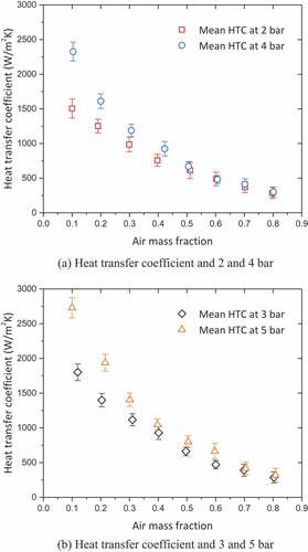
shows the measurement results of condensation heat transfer coefficients for the first set of test runs in which the air mass fraction is varied from 0.1 to 0.8 at each isobaric condition with the wall subcooling degree of around 40 K. A commonly reported behavior was reproduced; the heat transfer coefficient decreased with the air mass fraction by the buildup of the noncondensable species near the liquid–vapor interface, and increased with the total pressure as the steam density augments. It was also observed that the heat transfer coefficient varied little with pressure under air-enriched conditions, which is expected to be encountered in the early phase of the containment transient.
Figure 5. Condensation heat transfer coefficients versus the air mass fraction at isobaric conditions with the wall subcooling degree kept around 40 K (± 10%).
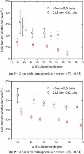
Plotted in are the experimental results for the variation of the heat transfer coefficient versus the wall subcooling degree measured in the second set. Since the decrease in the wall temperature results in the elevated air fraction in the vicinity of the liquid condensate and the lowered temperature and the liquid–vapor interface, the heat transfer coefficient was degraded in all the tests with an increase of the wall subcooling degree.
Figure 6. Condensation heat transfer coefficients versus the wall subcooling degree at 2 and 4 bar with atmospheric air present.
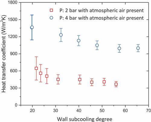
Note that, since the atmospheric air resides inside the containment at all times, the experimental range over which the partial pressure of air is less than 1 bar will not be observed in the accidental condition. According to the numerical analysis on the transient response of the containment equipped with the PCCS, the initiation of large break loss-of-coolant accident will be followed by the rapid rise in the containment pressure, within dozens of seconds, up to 4 bar [Citation4]. The wall subcooling degree is high at this early phase of the transient, while the condenser tube will lose continually its subcooling with an evolution of the accident. Thus, the test data obtained at 4 bar in can be regarded as an indication of the highest heat removal performance achievable for the investigated heat exchanger tube on practical containment conditions. For the condenser tube applied to JERICHO tests herein, the total rate of heat transfer became larger at higher wall subcooling degrees in the test range (the wall subcooling degree between 20 and 55 K), and the heat flux by the air-steam condensation was not more than 300 kW/m2; this value is not unique, but dependent on tube specifications (dimensions) as well as characteristics of the flow field established around the condenser tube.
3.3. Comparison to 40-mm-O.D. tube tests
The experimental data obtained from this study were compared to those of [Citation5] collected on the 40-mm-O.D. tube. Plotted in are the measured heat transfer coefficients versus the air mass traction at 2, 3, and 4 bar from both condenser tubes, and their variation according to the wall subcooling degree was shown in . Consistent augmentation of the condensation heat transfer coefficient was observed on a smaller diameter tube, i.e. with an increase of the surface curvature, provided the pressure, the air mass fraction, and the wall subcooling degree were the same. When the tube diameter was reduced from 40 mm to 21.5 mm, the heat transfer coefficient increased by 62% on average over the air mass fraction ranging from 0.1 to 0.8 at pressures investigated. The same phenomenon was also seen in the comparison results with ‘Program 2ʹ of [Citation5] which sought the effect of the wall subcooling degree on the heat transfer coefficient.
Figure 7. Comparison of heat transfer coefficients measured on 40-mm-O.D. and 21.5-mm-O.D. tubes in test runs conducted with varying the pressure and the air mass fraction while the wall subcooling degree being kept around 40 K.
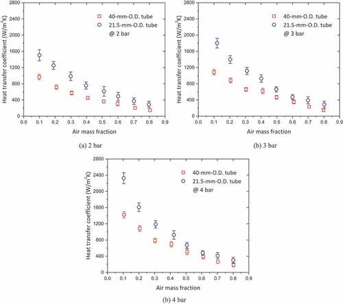
Figure 8. Comparison of heat transfer coefficients measured on 40-mm-O.D. and 21.5-mm-O.D. tubes in test runs conducted with varying the wall subcooling degree.
The above results provided a clear experimental evidence of a link between the heat transfer coefficient of the air-steam condensation and the tube diameter. Unless an empirical correlation or a mechanistic model for the condensation heat transfer coefficient is capable of predicting the effect of the tube diameter, it will be applicable only to condenser tubes having a comparable diameter with a referenced one on which the validation dataset was acquired, as shown in .
Using the collected data from JERICHO tests, the correction factor for this curvature effect used in past studies were assessed. An approximate function proposed by Popiel [Citation15] has been the most common choice in recently suggested condensation models based on heat and mass transfer analogy [Citation16], or diffusion layer theory [Citation17,Citation18], or empirical approach [Citation19]. The ratio of the cylinder-to-flat plate average Nusselt number was expressed as
where L and D denote the length and the diameter of the condenser tube, respectively. The application of EquationEquation (5)(5)
(5) as a correction factor seemed to be based on a presumption that the surface curvature would affect condensate rates the same way it affected the single-phase convection rates. Since the condensation heat transfer coefficient was not measured on a flat plate in JERICHO tests, EquationEquation (5)
(5)
(5) was assessed by means of calculating the ratio of the heat transfer coefficients on two condenser tubes with different diameters as following:
The calculation methods of mixture properties and the Grashof number are found in [Citation5].
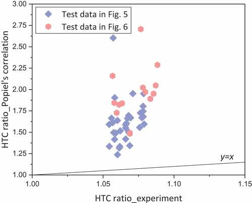
The ratio of the heat transfer coefficients calculated by EquationEquation (6)(6)
(6) was compared with the ratio of measured values on two condenser tubes in . The calculated ratio of the heat transfer coefficients on the 21.5-mm-O.D. tube to those on the 40-mm-O.D. tube was much smaller than the heat transfer coefficient ratio from the measured values. While the heat transfer coefficient ratio estimated by the Popiel’s correlation ranged from 1.05 to 1.09, the ratio calculated from the measured data exceeded 1.24 for all the test conditions covered. This indicates that, as the tube diameter gets smaller, the augmentation of the condensation heat transfer coefficient is more remarkable than the Popiel’s correlation predicts. While the Popiel’s correlation is applicable to free convection heat transfer in the laminar region, the turbulent natural convection flow of the air-steam mixture was established inside the test vessel of the JERICHO facility; the Grashof number ranged from 1.36 ∙ 1010 to 1.42 ∙ 1011 in the tests. In addition, it does not take into account the characteristics of the phase-change heat transfer such as the presence and effects of the liquid condensate on the surface, and the suction effect by the mass transfer of the gaseous mixture from the bulk and so on.
Figure 9. Comparison of the ratio of the heat transfer coefficient obtained from JERICHO tests to that estimated by the Popiel’s correlation expressed in EquationEquation (6)(6)
(6) .
Thus, it can be reasonably inferred that a non-negligible error will be introduced if one employs the approximate function about the ratio of the cylinder-to-flat plate average Nusselt number deduced from the single-phase-free convection heat transfer data to condensation problems in the presence of a noncondensable gas. This necessitates the development of a new multiplier to account for changes in the condensation heat transfer coefficient via the tube diameter on the basis of the experimental data from the JERICHO facility.
4. A multiplier for tube diameter
In this section, a new correction factor to define the relationship between the tube diameter and the condensation heat transfer coefficient over a vertical slender cylinder was derived based on the experimental results. The correction factor was proposed in the form of a multiplier applied to Lee correlation [Citation5], a non-dimensional formula in which the Nusselt number was correlated in terms of the Grashof number, the air mass fraction, and the Jakob number as:
where
It has been proven from the previous study that, for the condenser tube with moderate diameters around 40 mm, Lee correlation gave best predictions among commonly used correlations as it could forecast the condensation heat transfer coefficient for a wider range of the Rayleigh number than others could. Then, by multiplying the correction factor to EquationEquation (7)(7)
(7) , one can compute the heat transfer coefficient of the air-steam condensation for any cylindrical tube with outer diameter between 21.5 and 40 mm; this range is compliant to practically adoptable tube dimensions for heat exchangers of a containment-scale safety system.
To derive the functional form of the multiplier, the deviation of the heat transfer coefficients on the 10-mm-O.D. tube from those of the referenced tube needs to be evaluated over the entire range of test conditions. shows of the ratio of the heat transfer coefficient measured on the 21.5-mm-O.D. tube in test runs presented in to that of the 40-mm-O.D. tube calculated by EquationEquation (7)(7)
(7) , denoted as f expressed in EquationEquation (9)
(9)
(9) , with varying air mass fraction at isobaric conditions:
Figure 10. Ratio of the heat transfer coefficient measured on the 21.5-mm-O.D. tube in test runs presented in to that of the 40-mm-O.D. tube calculated by Lee correlation at various pressure and air mass fraction conditions.
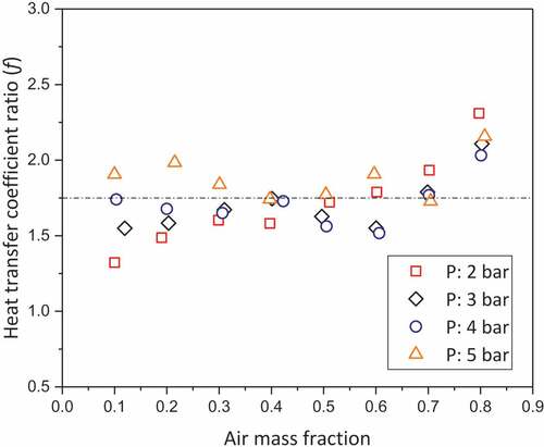
It should be noted that, in , was calculated from the empirical correlation, not taken from the measured data on the referenced tube, in order to compare the heat transfer coefficients under exactly the same conditions for the pressure, air mass fraction, bulk temperature, and surface temperature. shows that the ratio of the heat transfer coefficients did not reveal a clear link with the pressure and the mixture composition. They rather distributed sporadically around a mean value without exhibiting the relationship with experimental variables. Therefore, the multiplier for the surface curvature can be simply expressed as a function of the tube diameter.
As an additional dataset is not available between upper and lower bounds of outer diameter, the logarithmic variation of the heat transfer coefficient versus the tube diameter was assumed. This was based on the analytical study on film condensation of saturated vapor [Citation20] and free convective heat transfer on a vertical cylinder [Citation21], which proved that the curvature effect became pronounced when the radius of a tube was of the same order of magnitude as the boundary layer thickness. The adoption of the logarithmic function allows the multiplier curve to have a higher slope with decreasing the tube diameter. A total of 81 data points from the 21.5-mm-O.D. tube was fitted to a natural logarithmic function about f defined in EquationEquation (9)(9)
(9) as:
where D* = D/D0, and D0 represents the normalizing diameter (0.04 m). The use of the normalized diameter made the correlation simpler in the form because the length scale of interest in the research herein (dozens of millimeters) was much smaller than a unit length.
Then, the final form of the empirical correlation for the condensation heat transfer coefficient on a vertical slender cylinder under natural convection condition is as following:
where
and the multiplier for the tube diameter is given as:
The suggested multiplier for the surface curvature is valid over 21.5 mm ≤ D < 40 mm. Note that application of EquationEquation (10)(10)
(10) or EquationEquation (13)
(13)
(13) to extrapolate the condensation heat transfer coefficient out of this bound is not recommended. It is expected that the heat transfer coefficient gets closer to the value of a flat plate as the tube diameter is increased, while it will rise infinitely as the tube diameter becomes smaller [Citation20]. However, the developed multiplier was not designed to describe such an asymptotic behavior. The emphasis was placed on presenting a simple formulation valid within the bounds of the surface curvature covered in the JERICHO tests.
The average Nusselt number experimentally obtained in 21.5-mm-O.D. tube tests are compared to those predicted by the developed empirical correlation in . Calculated Nusselt numbers using EquationEquation (11)(11)
(11) were in good agreement with the measured data for the entire range of test conditions. The accuracy of the correlation against the test data was estimated by the standard deviation of the relative error (STDV) defined as:
Figure 11. Nusselt numbers predicted by the developed empirical correlation, EquationEquation (11)(11)
(11) , versus those obtained by JERICHO tests.
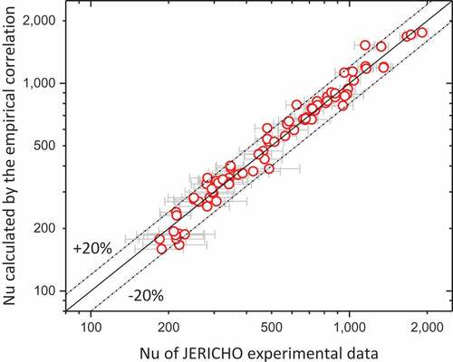
where C and M denote the calculated and measured average Nusselt number, respectively, and N is the total number of the test data. The standard deviation of average Nusselt number calculated using the multiplier applied to Lee correlation was 10.9% for test runs using the 21.5-mm-O.D. tube.
Since this study deployed a short tube of 1 m in length, it is worth discussing the curvature effect on the condensation heat transfer coefficient on a longer tube, up to 6 m for the prototypical design. The thickness and the mass flow rate of the liquid condensate increase with the condensing length because of continuous condensation at the liquid–vapor interface. In the presence of a noncondensable gas, however, the heat transfer rate is significantly affected by the steam concentration in the bulk, rather than the condensate thickness. Most of the thermal resistance occurs in the vapor-gas boundary layer between the liquid–vapor interface and the bulk.
Since the curvature effect on the heat transfer coefficient is basically related with the change in the diffusive mass flux of steam in the vapor-gas boundary layer, the inundation of the liquid condensate in a longer condenser tube may not change significantly the curvature effect observed in this study. One needs to note that the experimental results from the full-scale test, by Korea Atomic Energy Research Institute, with the 5 m long tube with the diameter of 31.8 mm lie exactly between the JERICHO test data of the 21.5-mm-O.D. tube and the 40-mm-O.D. tube [Citation8].
The empirical correlation developed in this study was further validated against an independent recent dataset obtained from the condensation test facility, named ATRON [Citation7]. This test facility was constructed by KHNP Central Research Institute for the study of natural convection and condensation inside the reactor containment building of iPOWER. The prototypical containment was scaled down by 1:20, and the test vessel of ATRON was designed to have a shape of thick slice, which is 1.349 m wide. The condenser tube was vertically installed as a single cylindrical pipe of 1000 mm in effective length and 31.8 mm in outer diameter. The local wall temperatures were measured by flush-mounted multiple thermocouples arranged in the circumferential direction at each elevation. The method to calculate the mean heat transfer coefficient was the same as that of this study. According to the test data presented in the recent publication, the pressure was varied from 2 to 5 bar, the air mass fraction 0.1 to 0.8, and the wall subcooling degree from 5 to 60 K. The effect of tube inclination was also studied in the subsequent series of experiment.
A comparison between the calculated heat transfer coefficients by the proposed correlation and the measurement data of ATRON at 3 and 4 bar is shown in . The proposed correlation showed a reasonable accuracy in predicting the heat transfer coefficient on a condenser tube with a different diameter; the deviation from the measured data was less than 12%. It is noted that, at 3 bar, the predicted heat transfer coefficients are generally higher than the measured data, whereas they are lower than the test data at 4 bar. In the proposed correlation, the pressure effect is taken into account by Lee correlation, EquationEquation (7)(7)
(7) . In the ATRON tests, the condensation heat transfer coefficient increased more drastically with increasing pressure than Lee correlation predicted. Nevertheless, the suggested correlation could gain wide applicability for tube dimensions under a wide variety of in-containment conditions through the above assessment.
Figure 12. Assessment of the proposed correlation against the heat transfer coefficients measured in ATRON [Citation9] at the pressure of 3 and 4 bar with the wall subcooling degree of 30 K.
![Figure 12. Assessment of the proposed correlation against the heat transfer coefficients measured in ATRON [Citation9] at the pressure of 3 and 4 bar with the wall subcooling degree of 30 K.](/cms/asset/78b1658d-9b7f-4892-a6bc-2e03d8fb251f/tnst_a_1736200_f0012_oc.jpg)
It was demonstrated that the prediction accuracy of the heat transfer coefficient of the air-steam condensation over a vertical cylinder could be enhanced by employing a multiplier for the tube diameter ranging from 21.5 mm to 40 mm. This correction factor for the curvature effect can also be used as a multiplier for the mass transfer coefficient, generally calculated based on the heat and mass transfer analogy, in a mechanistic model such as the Colburn-Hougen model in order to take into account the changes in the rate of heat transfer by the surface curvature.
5. Conclusion
The mean heat transfer coefficients of air-steam condensation were measured under natural convection conditions over a vertical slender cylinder of 21.5 mm in outer diameter. When test data were compared with those obtained on the 40-mm-O.D. tube in the previous tests, consistent increase in the condensation heat transfer coefficient was observed, which disclosed the curvature effect on steam condensation in the presence of a noncondensable gas. Based on the experimental results, it was also revealed that the approximate function proposed by Popiel, which the most common choice in recently suggested condensation models before this study, would lead to erroneous prediction provided it is used as a correction factor for the tube diameter.
A new multiplier for the surface curvature was proposed simply as a logarithmic function of the tube diameter for application to Lee correlation. It is expected that this can also be used as a multiplier for the mass transfer coefficient in a mechanistic model for steam condensation on a tube. As a future work, the complementary CFD analysis on the JERICHO tests will contribute not only to validate the steam condensation model embedded in the CFD code, but also to figure out clues to explain the change in the heat transfer coefficient by the tube diameter under the condensation environment.
Nomenclature
| As | = | Surface area (m2) |
| cp | = | Specific heat at constant pressure (J kg−1K−1) |
| D | = | Diameter (m) |
| D0 | = | Normalizing diameter (m) |
| D⃰ | = | Normalized diameter |
| f | = | Ratio of the cylinder-to-flat plate average heat transfer coefficient |
| Gr | = | Grashof number |
| = | Average heat transfer coefficient over length (W m−2 K−1) | |
| HTC | = | Heat transfer coefficient (W m−2 K−1) |
| Ja | = | Jakob number |
| L | = | Length (m) |
| = | Mass flow rate (kg s−1) | |
| = | Average Nusselt number over length (W m−2 K−1) | |
| = | Average Nusselt number for the referenced diameter, 40 mm (W m−2 K−1) | |
| P | = | Pressure (Pa) |
| T | = | Temperature (K) |
| = | Average temperature (K) | |
| U | = | Uncertainties |
| W | = | Mass fraction |
Greek letters
| = | Temperature rise of cooling water | |
| = | Temperature difference between the bulk and the wall | |
| = | Correction factor for the curvature effect |
Subscript
| 0 | = | Value of the referenced tube |
| a | = | Air |
| b | = | Bulk conditions |
| c | = | Cooling water |
| cyl | = | Cylinder |
| flat | = | Flat plate |
| i | = | Inlet |
| o | = | Outlet |
| s | = | Steam |
| w | = | Wall |
Acknowledgments
The authors are deeply grateful to Dr. Sang Gyu Lim of KHNP Central Research Institute for sharing valuable experimental data from ATRON. This work was supported by the Nuclear Power Core Technology Development Program of the Korea Institute of Energy Technology Evaluation (KETEP) granted financial resources by the Ministry of Trade, Industry and Energy, Republic of Korea [number 20161510400120].
Disclosure statement
No potential conflict of interest was reported by the authors.
References
- Xu H, Gu H, Sun Z. Forced convection condensation of steam in the presence of multicomponent noncondensable gases inside a horizontal tube. Int J Heat Mass Transfer. 2017;104:1110–1119.
- Fan G, Tong P, Sun Z, et al. Experimental study of pure steam and steam–air condensation over a vertical corrugated tube. Prog Nucl Energy. 2018;109:239–249.
- Lee SW, Heo S, Ha HU, et al. The concept of the innovative power reactor. Nucl Eng Technol. 2017;49:1431–1441.
- Ha H, Lee S, Kim H. Optimal design of passive containment cooling system for innovative PWR. Nucl Eng Technol. 2017;49:941–952.
- Lee Y-G, Jang Y-J, Choi D-J. An experimental study of air–steam condensation on the exterior surface of a vertical tube under natural convection conditions. Int J Heat Mass Transfer. 2017;104:1034–1047.
- Jeon BG, Kim DY, Shin CW, et al. Parametric experiments and CFD analysis on condensation heat transfer performance of externally condensing tubes. Nucl Eng Des. 2015;293:447–457.
- Kang J, Im S, Cheon J, et al. A parametric study of steam-air mixture condensation on a vertical tube under natural circulation condition. Proceedings of the 10th International Conference on Boiling and Condensation Heat Transfer; 2018 Mar 12–15; Nagasaki, Japan.
- Bae BU, Kim S, Park YS, et al. Condensation heat transfer of the steam-air mixture on bundle heat exchanger of PCCS (passive containment cooling system). Proceedings of the 18th International Topical Meeting on Nuclear Reactor Thermal Hydraulics; 2019 Aug 18–23; Portland, OR.
- Lim SG, Ohk SM, Lee JM, et al. Condensation heat transfer on a vertical tube with non-condensable gas. Transactions of the Korean nuclear society spring meeting; 2019 May 23–24; Jeju, Korea.
- Lim SG, No HC, Lee SW, et al. Development of stability maps for flashing-induced instability in a passive containment cooling system for iPOWER. Nucl Eng Technol. 2019;52:37–50.
- Lee Y-G, Jang Y-J, Kim S. Analysis of air-steam condensation tests on a vertical tube of the passive containment cooling system under natural convection. Ann Nucl Energy. 2019;131:460–474.
- Kawakubo M, Aritomi M, Kikura H, et al. An experimental study on the cooling characteristics of passive containment cooling systems. J Nucl Sci Technol. 2009;46:339–345.
- Colburn AP, Hougen OA. Design of cooler condensers for mixtures of vapors with noncondensing gases. Ind Eng Chem. 1934;26:1178–1182.
- Peterson PF, Schrock VE, Kageyama T. Diffusion layer theory for turbulent vapor condensation with noncondensable gases. J Heat Transfer. 1993;115:998–1003.
- Popiel CO. Free convection heat transfer from vertical slender cylinders: a review. Heat Transf Eng. 2008;29:521–536.
- Dehbi A. A generalized correlation for steam condensation rates in the presence of air under turbulent free convection. Int J Heat Mass Transfer. 2015;86:1–15.
- Yoo JM, Kang JH, Yun BJ, et al. Improvement of the MELCOR condensation heat transfer model for the thermal-hydraulic analysis of a PWR containment. Prog Nucl Energy. 2018;104:172–182.
- Lu J, Cao H, Li J. Diffusion layer model for condensation of vapor with the presence of noncondensable gas under natural convective condensation. Prog Nucl Energy. 2020;118:103078.
- Fan G, Tong P, Sun Z, et al. Development of a new empirical correlation for steam condensation rates in the presence of air outside vertical smooth tube. Ann Nucl Energy. 2018;113:139–146.
- Kim S, Lee Y-G, Jerng D-W. Laminar film condensation of saturated vapor on an isothermal vertical cylinder. Int J Heat Mass Transfer. 2015;83:545–551.
- Cebeci T Laminar-free-convective-heat transfer from the outer surface of a vertical slender circular cylinder. Heat Transf. 1974; Proc. Fifth Int. Conf. Vol. 3; 1974; Tokyo. p. 15–19.