
ABSTRACT
The typical initiating events of a core disruptive accident (CDA) in small sodium-cooled fast reactors (SFR) are evaluated with the computational code, SAS4A. CDA is one of the hypothetical events in the safety assessment of the SFR, as the SFR has the potential to experience power excursion due to the sodium voiding and the core degradation. To improve the safety of future SFRs, the development of SFRs with low void reactivity has been promoted. Small SFRs can have a negative void coefficient of reactivity. The analysis of the CDA event sequence in small SFRs is valuable for the investigation of the reactor characteristics for the future R&D of SFRs. The event progression during ULOF and UTOP, which are the typical initiating events of CDA, is investigated through the numerical analysis. The event progression of these accidents in the low void reactivity reactor is found to be slow due to the effective insertion of the negative reactivity feedback and the absence of significant positive reactivity insertion. No power excursion occurs in the initiating phase. In ULOF, the cladding melt and motion behavior becomes more important for the evaluation of the event progression due to its positive reactivity.
1. Introduction
A core disruptive accident (CDA) is one of the hypothetical events in the safety assessment of Sodium-cooled Fast Reactors (SFRs). The core is not in its optimal reactive configuration. For this reason, the SFR has the potential to cause power excursion due to the sodium voiding and the core degradation. Insertion of excessive reactivity could lead to the release of significant energy. To improve the safety of future SFRs, the development of SFRs with low void reactivity has been promoted as an effective design measure against CDA. In the case of large SFRs, the void coefficient of reactivity for the entire core approaches 0$ by designing the void reactivity of many regions to be negative. For example, the design of placing a sodium plenum adjacent to the top of the fuel subassembly enhances the neutron leakage during the coolant boiling, thereby reducing the void coefficient of reactivity. Small SFRs can also exhibit a negative void coefficient of reactivity due to their compact core geometry, resulting in significant neutron leakage. The safety characteristics of this reactor are identified by investigating the event sequence of the CDA.
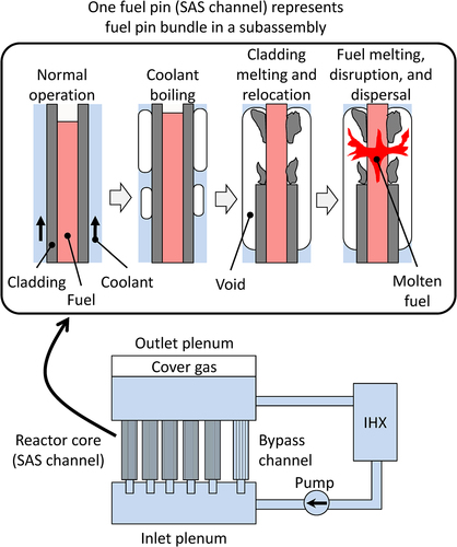
The SAS4A code [Citation1–5] is capable of investigating a variety of phenomena related to the early stage of the CDA, where the fuel pin is damaged in the intact wrapper tube and the materials move mainly axially. This stage is referred to as the initiating phase. The SAS4A code integrates mechanistic models to simulate the thermal-hydraulics and neutronic behavior in a sophisticated manner (). In order to assess the safety of nuclear power plants, the numerous subassemblies are organized into approximately 30 channels which are known as SAS channels. These channels are hydraulically connected to the upper and lower plenums, while the reactor power transient is calculated by point-reactor kinetics using core material reactivity worth maps and several reactivity feedback models.
Figure 1. Conceptual design of SAS4A.
This paper presents an analysis of a small SFR fueled with the mixed oxides, characterized by negative void coefficients of reactivity. The investigation uses the SAS4A code to clarify the event progression during the occurrence of two typical initiating events of CDA, namely Unprotected Loss Of Flow (ULOF) and Unprotected Transient Over-Power (UTOP). The physical phenomena appearing in small SFR accidents are first investigated, and the applicability of SAS4A is confirmed. Then, ULOF and UTOP are analyzed with the SAS4A code. The impact of the uncertainties arising from the analytical models and conditions on the event progression is evaluated in order to increase the reliability of the analysis results. Finally, parametric analyses with respect to negative void coefficients of reactivity are performed to investigate and assess whether the magnitude of these coefficients, which are important for core design, can lead to significant changes in the event progression.
2. Physical phenomena and applicability of analytical models during accidents in small SFRs
To perform the SAS4A analysis, the physical phenomena in the small SFR during the initiating phase are clarified and the applicability of the SAS4A analytical model is discussed. Specifically, based on the existing knowledge of large/medium SFRs, these physical phenomena are clarified, and the applicability is confirmed by considering the effect of the negative void coefficient of reactivity specific to small SFRs. In this study, small SFRs are defined as reactors where the small size of the core results in sufficient neutron leakage and are characterized by a negative void coefficient of reactivity, and large/medium SFRs are defined as reactors characterized by a positive void coefficient of reactivity, with a larger core size than small SFRs, which suppresses neutron leakage. ULOF and UTOP, which are typical CDA initiating events, are selected as target accident events.
2.1. General physical phenomena during CDA
In order to assess the CDA of large/medium SFRs, the event progression and the related physical phenomena have been elucidated from the accident simulation experiments, CABRI [Citation6–10] and TREAT [Citation11,Citation12], and the numerical analysis using the codes reflecting the results of these experiments. shows the general physical phenomena in large/medium SFRs during the initiating phase.
Figure 2. General physical phenomena during the initiating phase. The red and blue frames indicate positive and negative reactivity respectively. In the large/medium SFRs, the physical phenomena that cause the positive and negative reactivities described in the upper part of the figure occur. In the small SFRs, the physical phenomena that cause the negative reactivities described in the lower part of the figure occur.
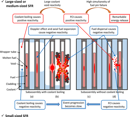
In the case of ULOF, as the coolant flow rate decreases, (a) the materials in a subassembly heat up and the coolant starts to boil in the high power-to-flow ratio subassembly. In the boiling subassembly, (b) the fuel is disrupted and dispersed after the cladding melting. Heating and boiling of the coolant introduce positive reactivity, whereas the Doppler effect, fuel axial expansion, and fuel dispersal introduce negative reactivity. If the positive reactivity due to the coolant boiling is sufficiently large, (c) even in a relatively low power-to-flow ratio subassembly, the power increases, the fuel melts, and the internal pressure of the fuel pins increases, leading to (d) fuel pin failure due to mechanical failure of the cladding while the coolant is not boiling. At this point, the fuel is dispersed, and the coolant is voided due to Fuel–Coolant Interaction (FCI). If the positive reactivity due to the coolant voiding is sufficiently large, the power ramp increases and fuel pin failure is accelerated, which could lead to prompt criticality and significant energy release. The coolant void reactivity is therefore a major contributor to the significant energy release during the initiating phase and is a very important design parameter. The previous studies of large SFRs have considered designs with limited coolant void reactivity to avoid significant energy release [Citation13].
In the case of UTOP, the control rod withdrawal reactivity increases power in the early stages of the initiating phase. Since the coolant flow remains at the rated conditions, (c) fuel melts while the coolant is not boiling and (d) fuel pin failure occurs. If the positive reactivity due to the coolant voiding is large enough, as the positive reactivity due to FCI increases the power, this progresses fuel pin failure, and FCI increases reactivity again. If the coolant void reactivity is not large enough, significant energy will not be released.
2.2. Event progression of small SFRs
The void coefficient of reactivity for the entire core is negative for small SFRs. The negative reactivity coefficient is expected to slowdown the event progression as shown in . In the case of ULOF, the event progresses very slowly because the large positive reactivity factor disappears at the stage of . The coolant then boils and can lead to fuel disruption as shown in . This causes the fuel to disperse and introduces the negative reactivity and the event progression becomes slower. In the case of UTOP, heating of the coolant causes negative reactivity and slows down the event progression. However, the coolant flow remains at the rated conditions, so the coolant temperature increases only slightly up to fuel pin failure. The negative void reactivity is relatively small. The Phenomena Identification and Ranking Table (PIRT) for UTOP [Citation5] shows that the coolant flow has a smaller effect on the event progression in UTOP compared to ULOF. Even if a fuel pin failure occurs as shown in , the reactivity changes due to coolant voiding by FCI are negative, resulting in a slower event progression. Therefore, very slow event propagation is expected in small SFRs compared to large/medium SFRs. Regarding the expansion of the damaged core region, each subassembly is damaged sequentially over a relatively long time in small SFRs, while numerous subassemblies are damaged within a short time in large/medium SFRs. However, since each physical phenomenon shown in is a local phenomenon within a subassembly, these phenomena are essentially the same for both small and large/medium SFRs. In in-pile experiments with slow event progression (e.g. pure LOF-type experiments where the coolant flow is reduced without power transient), extensive cladding melting and motion has been observed as a characteristic phenomenon. However, cladding melting and motion were observed in the medium SFR analysis, although the effect of this phenomenon on the event progression is small. While the degree of the effect of each phenomenon to the event progression in small SFRs may change from that of large/medium SFRs, the failure mechanism (fuel disruption due to cladding constraint release and fuel melt) and the post-failure behavior (thermodynamics, fluid mechanics, and heat transfer with fuel, steel, fission gas, and sodium) have not changed. Thus, it is assumed that , essentially, the same physical phenomena that occur in the ULOF and UTOP of large/medium SFRs will also occur in small SFRs.
2.3. Applicability of analysis model of SAS4A to small SFRs
Regarding the applicability of the analytical model to small SFRs, the SAS4A is considered applicable to small SFRs, where the event progression is slower than for large/medium SFRs, in the ULOF and UTOP. This is because SAS4A has mechanistic models to be able to simulate slow event progression, and the same physical phenomena that occur in the ULOF and UTOP of large/medium SFRs will also occur in small SFRs as described above. Under slow event progression, the post-failure material motion is dominated by complex behaviors such as friction between different materials and reduction of melt mobility due to heat transfer with structural materials. The SAS4A code has been developed to be able to handle the multi-phase, multi-component thermal-hydraulics behavior to simulate these phenomena. This code has been validated for each important phenomenon based on the above-mentioned experimental knowledge [Citation4,Citation5]. Based on the knowledge obtained from the CABRI in-pile experiment and the SAS4A validation analysis, the failure of the fuel can be predicted from the constraint condition of the cladding and the melting condition of the fuel [Citation5]. The constraint condition of the cladding on the failure of the fuel depends on the initiating event and the subsequent event progression. The failure criteria of ULOF and UTOP are described in Section 3 as analytical conditions.
3. Analysis conditions
3.1. Small SFR and accident conditions assumed in the analysis
This study considers a small SFR with a thermal power of about 100 MWth. The main specifications of the reactor are compared with those of a typical medium SFR in . The coolant void reactivity of this reactor with the entire core region completely voided is about −3.7$, whereas the typical medium SFR is about 4$. As shown in , the core is divided into the inner and outer regions with different plutonium (Pu) contents to reduce the radial power peaking factor. A low cycle number corresponds to low burn-up, and a subassembly with a low cycle number makes high power.
Figure 3. Core layout and channel arrangement for SAS4A code.
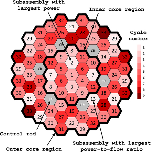
Table 1. Comparison of main specifications with typical medium SFR.
In this analysis, a total of 79 fuel subassemblies are organized into 33 SAS channels by considering their similarities in terms of coolant flow and burn-ups. In , the number assigned to each subassembly corresponds to the SAS channel number. Only subassemblies with the same coolant flow and burn-up could be grouped into the SAS channels in all subassemblies except the outermost subassemblies, which have a less influence on the event progression. Channel No. 2 is the largest-power subassembly because this subassembly is located near the center of the core and has low burn-up fuel. The largest power-to-flow ratio subassembly is Channel No. 13. This subassembly is located in the innermost layer of the outer core region and contains low burn-up fuel with high Pu enrichment. The coolant flow rate of the outer core region is smaller than that of the inner core region. The reflectors are installed both above and below the 500-mm-height fuel region.
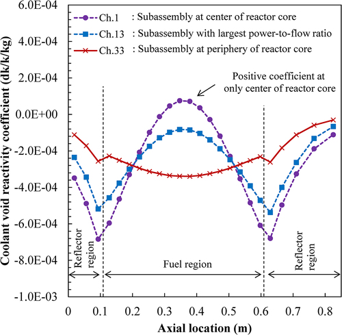
A reactor power transient is obtained using a point kinetics model based on the reactivity changes due to Doppler reactivity, axial expansion reactivity, coolant void reactivity, cladding motion reactivity, and fuel motion reactivity. The reactivity change due to coolant void, cladding motion, and fuel motion is calculated by the reactivity worth map of each material, respectively. Examples of the void coefficient of reactivity are shown in . These coefficients are negative for most regions.
Figure 4. Axial distribution of void coefficient of reactivity of representative SAS channel.
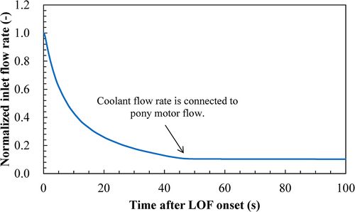
Mass flow rate in the primary pump during ULOF is considered as a coast-down curve shown in . The primary pump stop is assumed to reduce the coolant flow, which changes to a pony motor flow (about 8% of rated flow) about 50s after the LOF starts.
Figure 5. Normalized coolant inlet flow rate in ULOF.
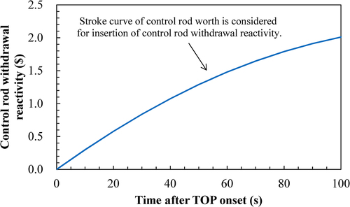
The initiating event in UTOP is assumed to be a positive reactivity insertion due to an erroneous control rod withdrawal. This reactivity insertion considers the control rod position and the control rod stroke curve, as shown in .
Figure 6. Control rod withdrawal reactivity in UTOP.
As mentioned above, it is necessary to determine the failure criteria according to the small SFRs. In ULOF, as mentioned above, the power decreases significantly after LOF for small SFRs due to the negative void coefficient of reactivity. As the radial temperature distribution in the fuel pellet flattens with decreasing power, it is expected that the fuel will be disrupted as soon as fuel melting starts at the fuel center. It is conservative to disrupt the fuel immediately after the onset of melt because the fuel dispersal has a negative reactivity effect, and the lower the fuel melt fraction at fuel disruption, the lower the fuel mobility and the less negative reactivity effect due to fuel dispersal. This conservative assumption is used in this study. In UTOP, the power increase causes the fuel to melt, and the internal pressure increase causes the cladding to rupture. The internal pressure depends on the melting condition of the fuel. It has been clarified that the failure criterion is represented by an areal melt fraction [Citation5]. Experimental data have shown that the high smear density fuels (approximately 90% TD) often used in small SFRs can fail when the areal melt fraction exceeds about 20%. Therefore, a 20% areal melt fraction was used as the UTOP failure criterion in this study.
The SAS4A code analyzed the small SFR using standard models and model parameters predicted from various in-pile experiments and design values (hereinafter referred to as the reference case). The cases in which the uncertainty of the analytical model and the analytical conditions is taken into account (hereinafter referred to as the uncertainty case) and the cases in which the coolant void reactivity is used as a parameter (hereinafter referred to as the parametric case) were also analyzed. The analytical conditions for the uncertainty cases and the parametric cases are described below.
3.2. Conditions of uncertainty cases
As described above, the event progression is dominated by the change in reactivity in the initiating phase of CDA. In this study, the analysis considering the uncertainty for each reactivity factor is performed to identify the effect on each event progression. summarizes the uncertainties to be considered in the uncertainty case. A basis for setting each condition is described below.
Table 2. Uncertainty considered in uncertainty case.
As for the uncertainties that greatly affect the reactivity, there are mainly the uncertainty of the reactivity coefficient and the phenomenon itself. Since the physical phenomena before pin failure (e.g. heat transfer and thermal expansion of the fuel pin, and heating and boiling of the coolant) are well known, the uncertainty of the phenomenon itself is small. Therefore, the uncertainty of the reactivity coefficients is considered for Doppler reactivity, axial expansion reactivity, and coolant void reactivity. The uncertainty in the reactivity coefficients usually depends on the nuclear characteristics of the target reactor and the nuclear data used in the analysis. In this study, a typical uncertainty value is assumed to identify the effect of the uncertainty in the reactivity coefficients on the event progression, and the uncertainty values used for each reactivity coefficient are the same so that their effects can be easily compared. A 30% uncertainty is considered for all reactivity factors, based on a 30% uncertainty in the reactivity coefficient used to evaluate a typical medium SFR [Citation14]. As for the uncertainty cases, the reactivity is reduced by the amount of uncertainty in the negative region of the void coefficient of reactivity and increased in the positive region of it since there are positive and negative regions of it in the core (see ). For Doppler reactivity and axial expansion reactivity, the uncertainty is conservatively considered according to the event progression because the reactivity is determined to be positive or negative with the event progression.
For the post-failure behavior, the uncertainties affecting the material motion behavior are considered, because the phenomenon itself has large uncertainties. As for cladding motion, the cladding melts and moves after the coolant boils and dries out. One of the driving forces is the shear stress caused by the flowing sodium vapor, which makes the molten steel move upward, increasing reactivity. The coefficient of friction between the molten steel and the sodium vapor is increased by a factor of 10 to promote the motion of the molten steel due to the interfacial shear force between them. As for fuel motion, as described in Section 2, the fuel motion is affected by the fuel melt state at the failure of ULOF and the analysis condition is set with the conservative assumption that the fuel is disrupted as soon as the fuel starts to melt. In UTOP, the failure criterion is set at a 20% areal melt fraction. In order to suppress the motion of the molten fuel with negative reactivity effects, the case where the fuel fails immediately after the start of melting is also analyzed. This criterion is the same as that for ULOF. On the other hand, the reactivity continues to increase as the control rod is withdrawn, so that the later the fuel pin fails, the more the power increases. Experimental data indicated that the high smear density fuels failed at 20–30% fuel areal melt fraction [Citation9]. Therefore, in order to identify the effect of the fuel melt state at the failure on the event progression, the case with a 50% areal melt fraction as the failure criterion, which is also used in the ULOF uncertainty case, is also analyzed.
3.3. Conditions of parametric cases
As mentioned in Section 1, coolant void reactivity is important for safety measures against CDA. Since the whole-core coolant void reactivity is determined by the core design, it is important to clarify the effect of this reactivity on the event progression by the analysis with this reactivity as a parameter. As shown in , this reactivity is about 4$ in the typical medium SFR and −3.7$ in the small SFR assumed in this study. In this study, complementary analyses between these reactivities, where the void coefficients of reactivity used in the SAS4A code were uniformly increased to set the whole-core coolant void reactivity to −2$, 0$, and +2$, are performed to elucidate the relationship between this reactivity and event propagation.
4. Assessment of ULOF event progression in small SFRs
4.1. Reference case in ULOF
This section describes the analysis results of ULOF event under the reference condition. show the calculated transition of the total reactivity, the normalized power, and the various reactivities of the ULOF reference case. The ULOF event progression is summarized as follows:
Figure 7. Transition of total reactivity and normalized power under ULOF reference condition.
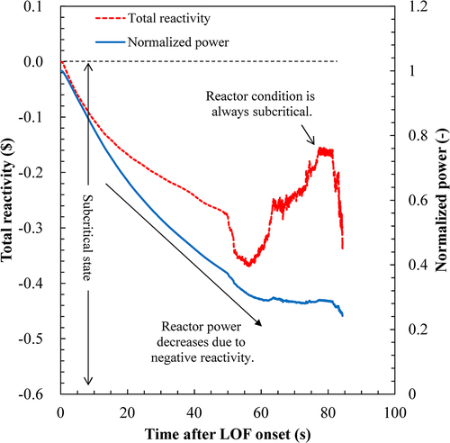
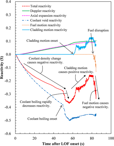
Figure 8. Transition of reactivity under ULOF reference condition.
The reduction in coolant flow resulted in an increase in the coolant temperature, leading to the insertion of negative reactivity.
The undercooled condition triggered the onset of coolant boiling despite the reduction in reactor power.
The onset of coolant boiling resulted in an elevation of the cladding temperature, which eventually led to melting and subsequent axial motion of the cladding.
The fuel experienced disruption as a result of fuel melting, leading to the insertion of negative reactivity through axial fuel dispersal.
The wrapper tube melted and failed as a result of the heat transfer occurring between the fuel and the wrapper tube.
The reactor remained in a subcritical state throughout the initiating phase.
After the LOF onset, the Doppler effect and axial expansion contributed to the reactivity increase due to the fuel temperature decrease because the reactor power decreased due to the negative void reactivity. However, these effects were relatively small compared to the coolant void reactivity, resulting in a negative reactivity as a whole. After the coolant boiling, the cladding motion also increased the reactivity. However, the reactor remained in a subcritical state since the coolant boiling caused a sufficiently large negative reactivity. After the fuel disruption, although the fuel motion can potentially generate positive reactivity, in this phase the motion was limited to the axial direction and the fuel was dispersed, decreasing reactivity. Finally, the wrapper tube failed at 84.3 s with coolant boiling in four subassemblies and cladding melting/displacement in two subassemblies. The extent of damage was limited to two subassemblies.
4.2. Impact assessment of uncertainties in ULOF
This section describes the following analytical cases considering the uncertainties described in Section 3.1. For the Doppler reactivity and the axial expansion reactivity, the reactivity coefficients are conservatively increased by the uncertainty, as it has a positive reactivity effect, as shown in .
Doppler reactivity +30% case
Axial expansion reactivity +30% case
Coolant void reactivity −30% case
Large sodium vapor friction case as cladding motion reactivity
Fuel melt fraction 50% case as fuel motion reactivity
show the effect of several uncertainties, such as Doppler reactivity, axial expansion reactivity, coolant void reactivity, large sodium vapor friction, and fuel melt fraction, on the total reactivity. In these figures, the timing of the main phenomena, namely, coolant boiling, cladding motion, and fuel disruption, is indicated by marks on the graphs for each analysis case. In all cases where the uncertainty of the reactivity coefficient is considered, the event progression is accelerated. The absolute value of the coolant void reactivity is larger than that of the others as shown in , so that the effect of this reactivity is the most significant. However, the change in overall reactivity was relatively small and the reactor remained still subcritical. Considering the uncertainty of the coolant void reactivity increased the number of boiling subassemblies to six. However, as in the reference case, only two subassemblies were damaged during the initiating phase. Due to the negative void coefficient of reactivity and the limited impact of positive reactivity effects, the effect of the uncertainties was not amplified even when the uncertainties associated with the reactivity coefficients were considered. Furthermore, the continued subcritical state of the reactor resulted in low sensitivity to changes in reactor power. As a result, the impact of uncertainties in the reactivity coefficients on the event progression was significantly reduced.
Figure 9. Transition of the total reactivity for the uncertainty cases of Doppler reactivity, axial expansion reactivity, and coolant void reactivity in ULOF.
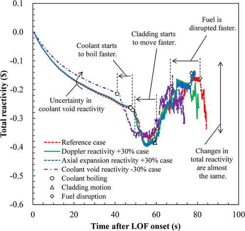
Figure 10. Transition of the total reactivity for the uncertainty cases of cladding motion and fuel motion in ULOF.
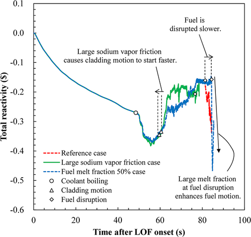
shows the transition of the total reactivity considering uncertainties related to the cladding and fuel motion. The large sodium vapor friction causes the cladding motion to start earlier and the reactivity to increase faster, as this friction acts as a driving force for the molten steel. However, no marked differences were observed in the final values of the cladding motion reactivity, and the variations in total reactivity and reactor power followed a similar behavior to that of the reference case. As in the reference case, only two subassemblies were damaged during the initiating phase.
Finally, in the case where uncertainties related to the fuel motion are considered, the time of fuel disruption is slightly delayed by 3 s, as the fuel is disrupted after it has melted sufficiently, and only one subassembly was damaged at the end of the initiating phase. In this case, the failure criteria used to predict the failure of the fuel in SAS4A analysis was greatly changed. As mentioned in Section 3.1., when the fuel melts, the temperature difference between the center and the surface of the fuel pellet is 10 K, which means that a significant change in the failure criteria would not have a significant effect on the failure time, since the melt region would expand immediately. The reactivity changes due to fuel motion after fuel disruption are larger than in the reference case as expected. This suggests that the failure criteria established in this study are considered to be reasonable.
The SAS4A analysis showed that the uncertainties did not have a significant impact on the event progression due to the effective insertion of negative reactivity feedback in small SFRs. Furthermore, the lack of significant positive reactivity insertion led to the slow event progression. Therefore, the potential for mechanical energy generation during the initiating phase was very low since the fuel motion was limited to the axial direction only and the power excursions due to concentrated fuel mass did not occur.
5. Assessment of UTOP event progression in small SFRs
5.1. Reference case in UTOP
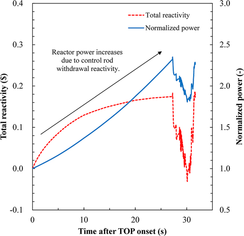
The accident progression for the UTOP event with the small SFR was analyzed by SAS4A in the same way as for ULOF. show the calculated transition of the total reactivity, the normalized power, and various reactivities of the UTOP reference case. The UTOP event progression is summarized as follows:
Figure 11. Transition of total reactivity and normalized power under UTOP reference condition.
The positive reactivity insertion from the control rod withdrawal increased power.
The power increase caused the fuel to melt, and the internal pressure increase caused the cladding to rupture.
Negative reactivity due to the fuel dispersal and the coolant voiding caused by FCI results in power decrease.
The wrapper tube melted and failed due to the heat transfer between the fuel and the wrapper tube.
The prompt criticality (1.0$) was never exceeded throughout the initiating phase.
Figure 12. Transition of reactivity under UTOP reference condition.
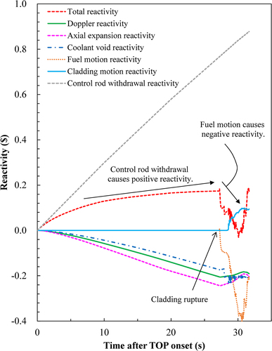
After the TOP onset, coolant density change, Doppler effect, and axial expansion contributed to the reactivity decrease due to the core temperature rise. However, these effects were relatively small compared to the control rod withdrawal reactivity, resulting in a positive reactivity as a whole. The cladding is relatively cold because the coolant flow remains at the rated conditions. On the other hand, the power increase causes the internal pressure increase, leading to cladding rupture. After the cladding rupture, the cladding also heats up due to coolant voiding caused by the FCI, resulting in fuel disruption. While the reactivity increases due to the cladding motion, the total reactivity is dominated by the reactivity due to fuel motion because the reactivity worth of the fuel is larger. The total reactivity increases to the same value as at the time of the failure after decreasing. This can be attributed to the fuel dispersal due to the fuel failure and the resulting negative reactivity insertion, which reduces the power and the driving force of the fuel dispersal, causing the upward dispersed fuel to fall and the axial fuel compaction. If the coolant void reactivity is positive, a positive reactivity is introduced by the FCI, resulting in a rapid increase in power and a large fuel motion reactivity due to the expansion of the damaged fuel region and the increase in fuel mobility is introduced. However, since the small SFR has a negative void coefficient of reactivity, the event progression is generally slow, and the fuel motion reactivity also shows a slow behavior. Finally, the initiating phase ends with the failure of the wrapper tube at 31.7 s after the TOP onset. The maximum power during the initiating phase was about 2.4 times the rated power, and only one subassembly was damaged at the end of the initiating phase.
5.2. Impact assessment of uncertainties in UTOP
In UTOP, the impact of uncertainties on event progression is assessed by the following analytical cases, considering the uncertainties described in Section 3.1, as in ULOF. For the Doppler reactivity and the axial expansion reactivity, the reactivity coefficients are conservatively decreased by the uncertainty, as it has a negative reactivity effect, as shown in . As for the post-failure, although the main reactivity factors are the cladding motion and the fuel motion, as mentioned in the previous section, the reactivity change due to the fuel motion is dominant in the UTOP. Hence, only the factors related to the fuel motion reactivity are focused on.
Doppler reactivity −30% case
Axial expansion reactivity −30% case
Coolant void reactivity −30% case
Fuel melt fraction 50% case as fuel motion reactivity
Fuel melt fraction 0% case as fuel motion reactivity
show the effect of several uncertainties, such as Doppler reactivity, axial expansion reactivity, coolant void reactivity, and fuel melt fraction, on the total reactivity. In these figures, the timing of the main phenomena (cladding rupture) is indicated by marks on the graphs for each analysis case.
Figure 13. Transition of the total reactivity for the uncertainty cases of Doppler reactivity, axial expansion reactivity, and coolant void reactivity in UTOP.
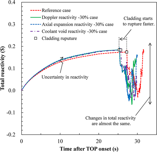
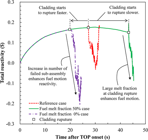
Figure 14. Transition of the total reactivity for the uncertainty cases of the failure criteria in UTOP..
The total reactivity was slightly increased by considering the uncertainty of the reactivity coefficient, indicating an acceleration of the event progression. However, the effect was small, and only a difference of about 2 s in the failure time was observed. As in the reference case, only one subassembly was damaged during the initiating phase. As mentioned above, the total reactivity up to failure is driven by the control rod withdrawal reactivity, and other reactivity factors suppress the reactivity increase. When the uncertainty in the reactivity coefficient is considered, the reactivity increases. However, the negative reactivity feedback reduces the reactivity, resulting in a smaller effect of uncertainty on the event progression.
In the case of 0% fuel melt fraction, the fuel fails immediately after melting. The earlier failure time increases the possibility of the simultaneous failure of the multiple fuel pins. However, only five subassemblies failed. The increased number of damaged subassemblies promoted negative reactivity insertion due to fuel dispersal and FCI, resulting in a larger negative reactivity insertion than in the reference case.
In the case of 50% fuel melt fraction, the maximum power increased to 3.5 times the rated power due to a later failure time. In the medium SFR, the best estimate case showed that the maximum power increased to 51 times the rated power and no mechanical energy was generated [Citation14]. Due to the large melt fraction at failure, the negative fuel motion reactivity was also large and, as in the reference case, only one subassembly was damaged during the initiating phase.
As in ULOF, the SAS4A analysis showed that the uncertainties did not have a significant impact on the event progression due to the effective insertion of negative reactivity feedback and the lack of significant positive reactivity insertion. As opposed to ULOF, the reactivity maintains a critical state (0$ or more) due to the control rod withdrawal reactivity. However, there are no other phenomena that cause a certain amount of positive reactivity. Since the positive reactivity caused by the cladding motion is less than the negative reactivity caused by the fuel motion, the overall material motion reactivity is negative. As a result, the event always proceeds slowly and the power excursion does not occur in the initiating phase of UTOP.
6. Impact of coolant void reactivity as a core characteristic on event progression
As discussed in Section 3.2, parametric studies on the coolant void reactivity were performed to elucidate its effect on the event progression. This section describes the following analytical cases with cores having the coolant void reactivity described in Section 3.2.
Coolant void reactivity −2$ case
Coolant void reactivity 0$ case
Coolant void reactivity +2$ case
shows the effect of the whole-core coolant void reactivity on the total reactivity in ULOF. Regarding ULOF, the negative reactivity effect of the heating and boiling of the coolant decreased as the void coefficient of reactivity increased. The total reactivity increased and exceeded 0$ in the case where the whole-core coolant void reactivity is 0$. shows the calculated transition of the reactivity components in the 0$ case. The coolant void reactivity was always positive because the coolant boils first in the positive void reactivity region near core center. The higher the whole-core coolant void reactivity, the higher the reactor power, resulting in a larger number of subassemblies experiencing coolant boiling. When the whole-core coolant void reactivity was 0$, 66 subassemblies experienced boiling, whereas when it was +2$, all subassemblies (79 subassemblies) experienced boiling. The number of subassemblies with cladding melting and motion also increased. The number of such damaged subassemblies was 20 in the 0$ case and 72 in the +2$ case, with damage extending throughout the core. Consequently, the cladding motion reactivity increases and has a large effect on the reactivity transition in the 0$ case, as shown in . The cladding motion also caused a larger reactivity in the +2$ case. At the same time, the coolant void reactivity also increased due to the increase in the void coefficient of reactivity. shows the effect of whole-core coolant void reactivity on the transition between coolant void reactivity and cladding motion reactivity. The figure shows that the coolant void reactivity is larger than the cladding motion reactivity in the +2$ case, which means that the coolant void reactivity has a larger effect on the event progression. As mentioned in Section 2.1, the positive void coefficient of reactivity introduces the positive reactivity in a sequential manner through the increase in coolant temperature and subsequent coolant boiling during ULOF in large/medium SFRs. The occurrence of phenomena that induce positive reactivity is accentuated by the escalation of reactor power, resulting in a progressively higher rate of power increase. As the whole-core coolant void reactivity increases, the reactivity increases due to the coolant boiling dominate the event progression and, consequently, the positive reactivity due to the cladding movement is expected to have less effect. Based on the above and focusing on the phenomena related to the positive reactivity, the event progression can be classified into the following three categories:
Figure 15. Transition of the total reactivity for the parametric cases of the coolant void reactivity in ULOF.
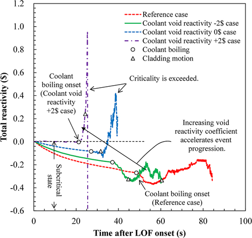
Figure 16. Transition of reactivity in ULOF coolant void reactivity 0$ case.
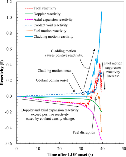
Figure 17. Transition of the coolant void and the cladding motion reactivity for the parametric cases of the coolant void reactivity in ULOF.
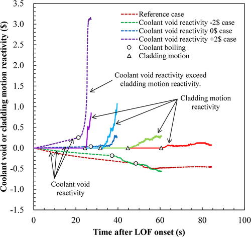
When the whole-core coolant void reactivity is sufficiently small and the reactor remains in a subcritical, the cladding motion has no significant effect on the event progression. This situation is simulated in the reference case.
When the whole-core coolant void reactivity is approaching 0$ and the transient coolant void reactivity has no significant contribution to the reactivity increase, the negative reactivity insertion by a heating and boiling of the coolant is suppressed. On the other hand, the positive reactivity insertion by melting and motion of the cladding becomes more important.
When the whole-core coolant void reactivity is large, heating and boiling of the coolant contributes significantly to the reactivity increase and dominates the event progression even before the reactivity increases due to the cladding motion. The cladding motion has no significant effect on the event progression.
The small SFRs belong to the categories (1) or (2). Therefore, in the analysis of the small SFR, the simulation of the cladding melt and motion behavior becomes more important than that of the core with the positive void coefficient of reactivity. Consequently, further studies are required in the future to validate the cladding motion model.
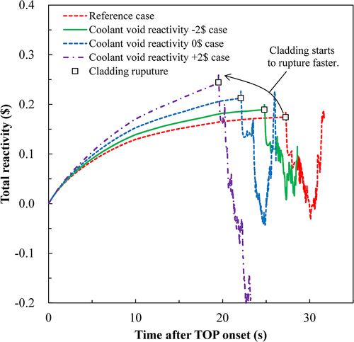
For UTOP, as shown in , the event progression did not change significantly, only slightly faster. As mentioned above, in UTOP, the reactivity up to failure is dominated by the control rod withdrawal reactivity, and an increase in the coolant void reactivity only slightly accelerates the event progression. Furthermore, as described in Section 2, the FCI is the only possible positive reactivity factor in UTOP even in large/medium SFRs. Unless the FCI is designed to cause a sufficiently large positive reactivity, the event progression will be slow in the initiating phase.
Figure 18. Transition of the total reactivity for the parametric cases of the coolant void reactivity in UTOP.
7. Conclusions
We have clarified the ULOF and UTOP event progressions of mixed oxide fuel-loaded small SFRs that are characterized by whole-core negative void reactivity through the SAS4A analysis.
In order to clarify the event progression of small SFRs with negative void reactivity, the ULOF and UTOP were analyzed with SAS4A under the reference condition as well as under the conditions considering the uncertainties. The event progression for small SFRs is slower than for large/medium SFRs, and the uncertainties did not have a significant impact on the event progression due to the effective insertion of negative reactivity feedback and the lack of significant positive reactivity insertion. In addition, parametric analyses with respect to whole-core void reactivity were performed to elucidate the correlation between the void reactivity and the event progression. Compared to the general behavior of large/medium SFRs with relatively higher positive void reactivity, reactors with low void reactivity were identified to have the following characteristics:
[ULOF]
The event progression is slowed down and becomes mild due to the effective insertion of negative reactivity feedback and the absence of significant positive reactivity insertion, thus keeping the reactor in a subcritical state throughout the initiating phase.
The cladding melt and motion behavior becomes more important for the evaluation of the event progression due to its positive reactivity when the whole-core coolant void reactivity is close to 0$ and the transient coolant void reactivity does not contribute much to the reactivity increase.
The possibility of generating mechanical energy during the initiating phase decreases. This is due to the restriction of fuel motion during this phase, which prevents power excursions by fuel concentration.
[UTOP]
The event progression is slower in the smaller SFRs due to the effective insertion of negative reactivity feedback and the absence of significant positive reactivity insertion.
The reactivity remains in a critical state due to the control rod withdrawal reactivity. There are no other effective positive reactivity insertion mechanisms as a result of limited fuel disruption and no power excursions occur in the initiating phase.
Acknowledgments
The authors wish to thank Mr Masahiro Mizuno of NESI Inc. for his contribution.
Disclosure statement
No potential conflict of interest was reported by the author(s).
References
- Tentner AM, Weber DP, Birgersson G et al., The SAS4A LMFBR whole core accident analysis code. Proceedings of the International Topical Meeting on Fast Reactor Safety; 1985 Apr 21-24; Knoxvill, USA; p. 989–997.
- Miles KJ, Hill DJ, DEFORM-4: fuel pin characterization and transient response in the SAS4A accident analysis code system. Proceedings of International Conference on Science and Technology of Fast Reactor Safety; 1986 May 12-16; Guernsey, UK; p. 51–58.
- Tentner AM, Miles KJ, Kalimullah HD, Fuel relocation modeling in the SAS4A accident analysis code system. Proceedings of International Conference on Science and Technology of Fast Reactor Safety; 1986 May 12-16; Guernsey, UK; p. 85–90.
- Ishida S, Kawada K, Fukano Y. Validation study of SAS4A code for the unprotected loss-of-flow accident in an SFR. Mech Eng J. 2020;7(3):19–00523. doi: 10.1299/mej.19-00523
- Ishida S, Fukano Y. Study on initiating phase of core disruptive accident (Validation study of SAS4A code for the unprotected transient overpower accident. J Jpn Soc Mech Eng. 2022;88:21. in Japanese.
- Heusener G, Cowking CB, Dadillon J et al., The CABRI-programmes- Motivations and achievements, Proceedings of International Fast Reactor Safety Meeting; 1990 Aug 12-16; Snowbirs, Utah; p. 197–207.
- Haessler M, Struwe D, Butland ATD et al., The CABRI2 programme - Overview on results. Proceedings of International Fast Reactor Safety Meeting; 1990 Aug 12-16; Snowbirs, Utah; p. 209–221.
- Sato I, Lemoine F, Struwe D. Transient fuel behavior and failure condition in the CABRI-2 experiments. Nucl Technol. 2004;145(1):115–137. doi: 10.13182/NT04-A3464
- Fukano Y, Onoda Y, Sato I, et al. Fuel pin behavior under slow-ramp-type transient-overpower conditions in the CABRI-FAST experiments. J Nucl Sci Technol. 2009;46(11):1049–1058. doi: 10.1080/18811248.2009.9711615
- Fukano Y, Onoda Y, Sato I. Fuel pin behavior up to cladding failure under pulse-type transient overpower in the CABRI-FAST and CABRI-RAFT experiments. J Nucl Sci Technol. 2010;47(4):396–410. doi: 10.1080/18811248.2010.9711970
- Wright AE, Dutt DS, Harrison LJ, Fast reactor safety testing in TREAT in the 1980s, Proceedings of International Fast Reactor Safety Meeting; 1990 Aug 12-16; Snowbirs, Utah; p. 233–243.
- Fukano Y. Comprehensive and consistent interpretation of local fault experiments and application to hypothetical local overpower accident in Monju. J Nucl Sci Technol. 2013;50(9):950–965. doi: 10.1080/00223131.2013.817319
- Sato I, Tobita Y, Konishi K, et al. Safety strategy of JSFR eliminating severe recriticality events and establishing in-vessel retention in the core disruptive accident. J Nucl Sci Technol. 2011;48(4):556–566. doi: 10.1080/18811248.2011.9711733
- Sato I, Tobita Y, Suzuki T et al. Analysis of ULOF accident in Monju reflecting the knowledge from CABRI in-pile experiments and others. Oarai-Machi (Japan): Japan Atomic Energy Agency; 2007; p. 1–84. (JAEA-Research 2007-055) [in Japanese]. https://doi.org/10.11484/jaea-research-2007-055