
ABSTRACT
CEA has manufactured a series of Fukushima Daiichi fuel debris simulants, either with depleted uranium oxide or with hafnium oxide as a surrogate of UO2. In ex-vessel compositions resulting from an interaction between corium and concrete, the oxidic phase density becomes lighter than that of the metallic phase, which segregates at the bottom. Three of these metallic phases have been mechanically cut at CEA Cadarache with handsaw and with core boring tool in FUJISAN facility. It appeared that two of these metallic blocks were extremely hard to cut (one from a fabrication with uranium oxide, the other from a simulant block) while the last one was more easily cut. The similarities and differences in metallographic analyses (SEM-EDS and XRD) of these three metal blocks will be presented and discussed. This experience provides useful learnings in view of the cutting and retrieval of fuel debris from Fukushima Daiichi.
1. Introduction
One of the important challenges for the decommissioning of the damaged reactors of the Fukushima Daiichi Nuclear Power Station (1F) is the fuel debris retrieval. In this context, the URASOL project [Citation1], which has been undertaken by the French consortium laboratories consisting of ONET Technologies, CEA, and IRSN for JAEA/CLADS, is dedicated to acquire basic scientific data on the generation and characteristics of radioactive aerosols from the thermal or mechanical processing of fuel debris simulant. This project has been organized by the International Research Institutes for Nuclear Decommissioning (IRID).
In this frame, CEA has manufactured a series of Fukushima Daiichi fuel debris simulants, either with depleted uranium oxide or with hafnium oxide as a surrogate of UO2 [Citation2,Citation3]. For ex-vessel compositions representing an interaction between corium and concrete, a metallic phase segregates from the oxidic phase because of a significant density contrast between molten metal and corium-concrete melt. Three of these metallic phases have been mechanically cut at CEA Cadarache with core boring tool in FUJISAN facility [Citation1] as well as manually with a hacksaw.
This paper reports the experience from these mechanical cutting. Actually, it appeared that two of these metallic blocks were extremely hard to cut (one from a fabrication with uranium oxide, the other from a simulant block) while the last one was more easily cut. This paper aims at providing some insights on the cutting difficulties that have been experimentally observed and compare this with material analyses. In a first section, the samples will be described, and then insight will be given from the material analyses. Finally, the links between metallic phase composition and the cutting response will be discussed.
2. Fuel debris simulant samples
Three fuel debris simulant samples have been considered in this study: VF-U3 prototypic fuel debris blocks including depleted uranium dioxide and VF-08 simulant composition have been directly fabricated from powders while VF-U1 has been produced by a Molten Core Concrete Interaction experiment with prototypic materials [Citation4].
2.1. VF-U3 fuel debris prototype
VF-U3 fuel debris prototype composition has been determined [Citation5] (Journeau, et al., 2017) in order to simulate a debris from interaction between the molten core and the concrete in the sump of Fukushima Daiichi Unit 1 (1F1). This composition () is based on the corium melt composition from ‘MAAP LP case’ by Robb et al. [Citation6], an ablation of 65 cm in the pedestal sump [Citation6], the Fukushima Daiichi concrete composition reported by Kitagaki at al. [Citation7] and the fission product composition 10 years after shutdown from Nishihara et al. [Citation8].
Table 1. VF-U3 load composition.
A 40.5 kg load (with the composition given in ) has been installed in a zirconia crucible within VULCANO test facility [Citation9] and melted by induction heating. Metallic pellets and balls are used as susceptor to start the heating process () as oxides are not conducing electricity at low temperatures.
Figure 1. VF-U3 load preparation in VULCANO facility. Left: sketch of crucible (inner diameter 26 cm) within induction coil – right: view during loading showing 3 stainless steel pellets.
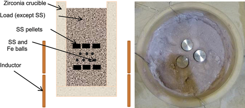
A power of the order of 40 kW has been injected for about 40 minutes under nitrogen flow. Thanks to the presence of a large layer of powder at the top, no measurable elevation of temperature has been observed at the top surface throughout the test.
Then, the power has been gradually decreased as a means to reduce the risks of ceramic debris cracking. After 1 hour 10 minutes of heating, induction has been turned off. More than 24 hours are necessary to completely cool down the load and the surrounding sand in order to collect the fabricated prototypic fuel debris, after removal of the unmelted top layer.
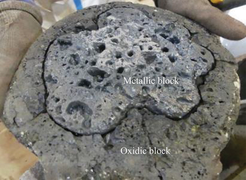
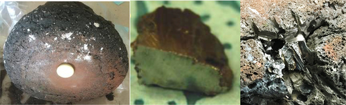
Due to the large density difference between the corium-concrete oxidic phase and the metallic phase, a metallic block has segregated at the bottom () and was easily separated from the oxide.
Figure 2. VF-U3 ex-vessel fuel debris prototype: upside-down view of lower part (approximate diameter: 25–26 cm).
2.2. VF-U1 prototypic molten core concrete interaction test
In the VULCANO VF-U1 test [Citation4,Citation10], an uranium-containing molten core prototypic melt (initial composition provided in ) had interacted with basaltic concrete () in VULCANO facility. The concrete cavity had an initial inner diameter of 25 cm. After high power melting, an average power of 38 kW has been injected by induction during 900 s, leading to the ablation of 9.6 dm3 of concrete by 46.4 kg of initial corium concrete mixture. A metallic layer (; metal phases are visualized thanks to the positioning of magnetsFootnote1) has been found after dismounting at the bottom of the concrete cavity [Citation11].
Figure 3. VF-U1 MCCI post-test view with metallic layer marked by magnet. Left: before fuel debris removal. Right: with only metallic block remaining.
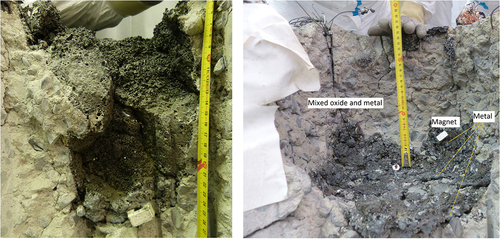
Table 2. VF-U1 corium load initial compositions [Citation4].
Table 3. VF-U1 concrete composition from ICP-AES analyses (oxides estimated from elemental analysis) [Citation12] normalized to 100%.
2.3. VF-08 simulant fuel debris
VF-08 simulant fuel debris has been fabricated [Citation5] from the same composition as VF-U3 except that each mole of uranium has been replaced by one mole of hafnium and ruthenium has been removed due its chemical toxicity for these tests carried out outside of VULCANO containment (). presents the induction setup used for VF-08. Protective sand is installed between coil and crucible as well as outside the coil. A Rogoswski probe is around the coil to measure the current in the inductor. A hood is installed to collect the fumes while nitrogen is flowed over the crucible to simulate the PCV nitrogen atmosphere.
Figure 4. The VF-08 induction melting setup.
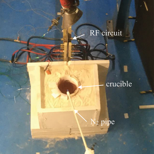
Table 4. VF-08 load composition (wt%).
As for VF-U3 and VF-U1, a metallic block has been segregated at the bottom ().
Figure 5. VF-08 ex-vessel fuel debris simulant. (Block diameter is about 25 cm) Left: metallic block indicated by magnet. Center: cut metal sample. Right: zoom on the metallic block showing the remains of hacksaw cutting.
3. Material analyses
Material analyses have been carried out at CEA on samples from these three metallic blocks. It includes X-Ray Diffraction (XRD), Scanning Electron Microscopy (SEM) with Energy Dispersive Spectroscopy (EDS) as well as Vickers microhardness measurements.
3.1. X-Ray diffraction
X-ray diffraction has been obtained with a D8 ADVANCE diffractometer from BRUCKER AXS equipped with a copper cathode tube. As metallic samples could not practically be crushed into powder, micro-collimated beam XRD has been applied to determine their diffraction patterns. Diffraction line indexing was performed with DiffracEva software from Bruker AXS with the 2020 Power Diffraction Files (PDF) international database.
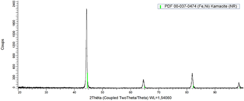
XRD pattern of VF-U3 () presents only the line from kamacite (bcc-Fe0.94Ni0.06). Kamacite is a solid solution of nickel in α-Fe that is found in metallic meteorites [Citation13]. It is a magnetic mineral with a Curie point around 800°C [Citation14].
Figure 6. XRD pattern of VF-U3 metallic sample.
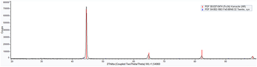
Similarly, VF-08 sample XRD pattern only show the presence of kamacite. For VF-U1 (), another phase is detected in addition to kamacite: taenite (fcc-Fe0.68Ni0.32). Taenite is also naturally found in metallic meteorites, often in conjunction to kamacite [Citation15] and is magnetic, although with a lower Curie point (around 500°C [Citation14]). Rietveld analysis has been carried out using the DIFFRAC.TOPAS v6 software distributed by Bruker. It estimates a 3-wt% taenite, 97% kamacite composition for this sample.
Figure 7. XRD pattern of VF-U1 metallic sample.
3.2 Scanning electron microscopy and EDS
The XRD analyses are complemented by Scanning Electron Microscopy (MERLIN from Carl Zeiss) with Energy Dispersive X-ray spectroscopy (EDX) using an X max detector from Oxford Instruments. From an international round robin on EDX analyses of oxidic corium samples [Citation16], uncertainties of about 1/10th of the measured values can be considered, except for light elements like oxygen. A systematic error (bias) of 1/4th of the oxygen fraction shall be taken into account in this uncertainty estimation.
Scanning Electron Microscope observation of VF-U3 metallic block () with EDS analyses indeed shows that it is mainly made of an iron-nickel alloy with small chromium content (e.g. area 14: 95 at% Fe, 4% Ni, 1% Cr, traces Mo). There are nevertheless some inclusions: silica (point 15), metallic alloys (point 17 and 22: mainly Sn-Ni; point 23: mainly Te-Sn) and iron-chromium mono-sulfides (points 18 and 20 with 8 at% Cr). Fission product elements such as tellurium (47 at% of point 23) or palladium (4 at% of point 17) are visible at significant concentrations in some of these inclusions.
Figure 8. Typical SEM micrographs of VF-U3 metallic block.
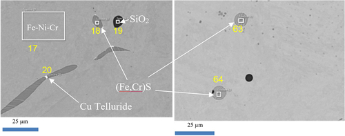
VF-08 exhibits a similar aspect () with a major phase close to a chromium-alloyed kamacite (zone 17: 93 at% Fe, 5% Ni, 2% Cr). Grey inclusions of about 5 µm are rich in sulphur, iron, chromium and copper (point 18: 26 at% Fe, 19% Cr, 0.4% Cu, 54% S; points 63 and 64: 38 at% Fe, 20% Cr, 1% Cu, 40% S). Dark phase (round particles of about 5 µm) have a composition close to that of silica (point 19: 34.5 at% Si, 0.5% Fe, 65% O). Smaller precipitates (a few µm) of a copper-tellurium compound, maybe copper telluride Cu2Te, are shown in white (point 20: 57 at% Cu, 31% Te, 7% Fe, 1% Cr, 3% S – it is possible that some Fe, Cr, S in this analysis come from surrounding long sulphide inclusion).
Figure 9. Typical SEM micrograph of VF-08.
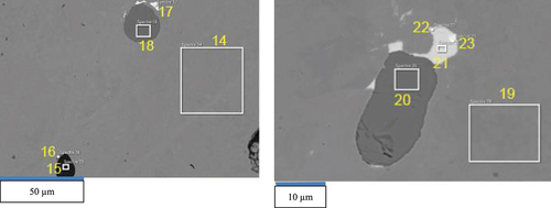
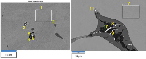
VF-U1 metallic block SEM-EDS analyses (points 1, 6, 7 of and Brissonneau et al. [Citation10]) indicate a matrix composition between Fe0.88Ni0.12 and Fe0.89Ni0.11. It must be noted that the phase diagram indicates a mixture of fcc and bcc phases for these compositions [Citation10] as found by XRD analysis. Some sulfides have also been detected (points 2, 3, 5, 11 as well as point S8–19 in Brissonneau et al. [Citation10] are close to FeS with a maximum of 2 at% Cr). A chromite composition (close to FeCr2O4) is also observed. Other oxidic inclusions have been detected such as compositions close to fayalite (Fe2SiO4 at point 8) and uranium-zirconium oxide (point 10) or silicate matrix (point 9).
Figure 10. Typical inclusions in VF-U1 SEM micrographs (scale is 50 µm at left and 10 µm at right).
3.3. Vickers microhardness
Microhardness measurements have also been carried out, using a DUROSCAN Vickers testing machine. presents the 37 measurement points on VF-U3 metallic sample with a zoom on one of the Vickers pyramids. A standard deviation of 10% has been observed. The results are synthesized in . The measured hardnesses are about twice higher than the 120–150 HV reported for powder metallurgy Fe0.9Ni0.1 alloy [Citation17]. Presence of sulfur has been reported to increase the hardness of Fe-Cr alloys [Citation18].
Figure 11. Vickers microhardness imprints for VF-U3 sample.
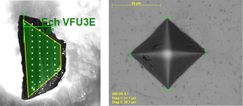
Table 5. Vickers microhardness results.
4. Mechanical cutting and discussion
4.1. Mechanical cutting
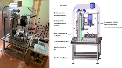
Mechanical cutting has been carried out in FUJISAN facility (). FUJISAN is mainly composed of a spindle motor, a custom drilling column and a scale located in a sealed enclosure installed on a frame. A core-boring tool (Wurth diamond surface deposit core bit) has been installed under the Isel 1500WL spindle motor column.
Figure 12. FUJISAN experimental setup (left: photograph – right: sketch).
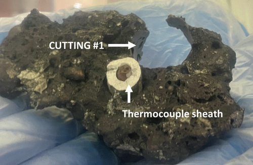
Boring metallic samples VF-U3 () or VF-08 () has been quite difficult, whereas it was easier for VF-U1 block ().
Figure 13. View of VF-U3 block after core boring with ⊘15 mm (CT_#8EV_M_15_1) and ⊘25 mm (CT_#8EV_M_25_1) tools.
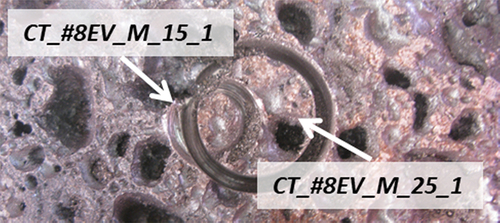
Figure 14. View of VF-08 metallic block after 3 core boring tests with ⊘25 mm tool and one (lower left) with ⊘15 mm tool.
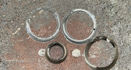
Figure 15. View of VF-U1 metallic bock after cutting with ⊘15 mm tool (core bore has broken out of the block).
summarize the core boring progression for the 3 studied metallic samples; for VF-U3 sample, tests have been made with two diameters of bits (15 and 25 mm). Two different behaviors are observed: VF-U3 and VF-08 present similar behavior with low boring speed (0.3–0.5 mm/min) even though the force on the tool (8–10 daN) was larger than that used for the VF-U1 metallic debris (5 daN) for which 2 mm/min were achieved.
Table 6. Characteristics of metal core boring tests.
This behavior was empirically confirmed during the cutting of samples for analysis with a hand-held hacksaw. Whereas VF-U1 metallic block was quite easy to cut, painful efforts were required to cut centimeter-scale samples from VF-U3 and VF-08 metallic blocks ( right presents a view of the VF-08 sample that required approximately one half hour to be manually cut with the hacksaw).
4.2 Discussion
Hardness of the major metallic phase does not seem to be the major parameter explaining the different behavior of these blocks as VF-U1 hardness is only slightly higher than that of VF-08.
In terms of differences between the two sets of metallic debris prototype, the following have been observed:
Concerning the introduced elements, VF-U3 and VF-08 included fission product prototypes and boron carbide (even though no boride has been observed in the metallic samples). These elements were not introduced in VF-U1, where, on the opposite, all the minor elements of concrete (in particular sodium and potassium oxides) are present, but were not found in the metallic blocks, except for sulfur.
Whereas VF-U3 and VF-08 diffraction pattern only present a bcc kamacite, VF-U1 indicates the presence of fcc-taenite in addition to bcc-kamacite. This corresponds to a higher remaining fraction of nickel in the metal for VF-U1 scenario (shorter considered MCCI time, thus lower oxidation of steel) compared to VF-U3. Petrovic [Citation19] reports that increasing the nickel fraction from 4 to 11-12% will almost double the yield and tensile strength of Fe-Ni alloys at room temperature;
The observed inclusions are also different: SiO2 and Fe(Cr)S for VF-U3 and VF-08; FeCr2O4, FeS, FeSiO4 and silicate for VF-U1. Iron sulfide hardness is reported to be about 3 times lower than that of steel [Citation20]. For the Young modulus, FeS (~45 GPa) is about 4 times less important than steel [Citation20].
These differences do not currently provide any evident reason for the observed differences with respect to mechanical cutting. Further R&D would be needed to understand this effect that may affect mechanical cutting during Fukushima Daiichi fuel debris retrieval.
5. Conclusions
Three metallic blocks representative of Fukushima Daiichi molten core concrete interaction products have been fabricated at CEA Cadarache. It appears that two of those metallic debris simulants have been very difficult to cut (both remotely by core boring and manually by hacksaw). Moreover, this study does not consider interfaces between metallic and ceramic debris which are known to further exacerbate the difficulty of mechanical cutting.
X-Ray Diffraction patterns, Scattering Electron Microscopy with Energy-Dispersive Spectroscopy and Vickers microhardness have been obtained and discussed for the three metallic samples. Differences in terms of main metallic phases (bcc-Fe0.94Ni0.06 vs. bcc-Fe0.94Ni0.06 + fcc-Fe0.68Ni0.32) linked to nickel content in metallic phase have been observed between hard and easy to cut blocks, as well as differences in terms of inclusions. Micro hardness of the Fe-Ni alloy does not seem correlated to its response to cutting.
Further R&D is thus necessary to explain the observed phenomena. Nevertheless, this experience provides nevertheless useful learnings in view of the mechanical cutting and retrieval of fuel debris from Fukushima Daiichi.
Acknowledgments
Most of this work has been carried out within the scope of contributions to the Japanese governmental subsidy program “Project of Decommissioning and Contaminated Water Management (Development of Analysis and Estimation Technology for Characterization of Fuel Debris)” funded by the Japanese Ministry of Economy, Trade and Industry (METI) and organized by the International Research Institute for Nuclear Decommissioning (IRID).
Disclosure statement
No potential conflict of interest was reported by the author(s).
Additional information
Funding
Notes
1. From the experience of previous MCCI experiments in which the metallic phase was always magnetic (mainly iron-nickel alloys), a simple magnet has been used to show the metallic phase in and left. The iron-nickel nature of this metallic phase has later been confirmed by the analyses presented in Section 3.
References
- Porcheron E, Leblois Y, Bouland A, et al. Particle generation test using simulated uranium containing debris: the URASOL project in the framework of Fukushima Daiichi dismantling, Proceedings DEM-2021; 2021 Sept 13-15; Avignon, France.
- Journeau C, Roulet D, Porcheron E, et al. Fukushima Daiichi fuel debris simulant materials for the development of cutting and collection technologies. J Nucl Sci Technol. 2018;55(9):985–995. doi: 10.1080/00223131.2018.1462267
- Journeau C, Molina D, Domenger R, et al., Characterization of prototypic corium sample simulating Fukushima Daiichi unit 2 lower head composition. Proceedings ERMSAR-2022; 2022 May 16-19;Karlsruhe, Germany.
- Bouyer V, Journeau C, Haquet JF, et al., Large scale VULCANO molten core concrete interaction test considering Fukushima Daiichi condition. Proceedings ERMSAR-2019; 2019 Mar 18-20; Prague, Czech Rep.
- Journeau C, Monerris J, Tormos B, et al. Fabricating Fukushima Daiichi in-vessel and ex-vessel fuel debris simulants for the development and qualification of laser cutting technique. Proceedings ERMSAR-2017; 2017 May 16-18; Warsaw, Poland.
- Robb K, Francis M, Farmer M Ex-Vessel Core Melt Modelling Comparison between MELTSPREAD-CORQUENCH and MELCOR 2.1. Oak Ridge National Lab. 2014. (Report ORNL/TM-2014/1).
- Kitagaki T, Yano K, Washiya T Research approach of MCCI products characterization for debris removal. Proceedings IEM on Strengthening Research and Development Effectiveness in the Light of the Accident at the Fukushima Daiichi Nuclear Power Plant; 2015 Feb 16-20; Vienna, Austria (Poster ID IAEA-CN-235-85).
- Nishihara K, Iwamoto H, Suyama K Estimation of Fuel Compositions in Fukushima-Daiichi Nuclear Power Plant. Japan: JAEA; 2012. (JAEA Report JAEA-Data/Code 2012-018).
- Journeau C, Bouyer V, Charollais F, et al. Upgrading the PLINIUS platform toward smarter prototypic-corium experimental R&D. Nucl Eng Des. 2022;386:111511. doi: 10.1016/j.nucengdes.2021.111511
- Brissonneau L, Ikeuchi H, Piluso P, et al. Material characterization of the VULCANO corium concrete interaction test with concrete representative of Fukushima Daiichi Nuclear Plants. J Nucl Mater. 2020;528:151860. doi: 10.1016/j.jnucmat.2019.151860
- Nakayoshi A Knowledge obtained from dismantling large-scale MCCI experiment products for decommissioning of Fukushima Daiichi Nuclear Power Station. Proceedings FDR 2019; 2019 May 24-26; Fukushima, Japan, J-village.
- Laffolley H. Synthèse de microparticules de silicate riches en césium parinteraction de combustible en fusion avec du béton - Simulation expérimentale de phénomènes présents lors de l’accident de Fukushima Daiichi [ PhD thesis]. Nantes, France: IMT Atlantique; 2023.
- Jaeger RR, Lipschutz ME. X-ray diffraction study of kamacite from iron meteorites. Geochim Cosmochim Acta. 1968;32(7):773–779. doi: 10.1016/0016-7037(68)90011-2
- Pechersky DM, Markov GP, Tsel’movich VA et al. Extraterrestrial magnetic minerals. Izv Phys Solid Earth. 2012;48(7–8):653–669. doi: 10.1134/S1069351312070051
- Albertsen JF, Knudsen JM, Gensen GB. Structure of taenite in two iron meteorites. Nature. 1978;273(5662):453–454. doi: 10.1038/273453a0
- Brissonneau L, Journeau C, Piluso P et al. Prototypic corium analysis: a round robin for SEM and EDS characterisation. IOP Conf Ser Mater Sci Eng. 2011;32:012005. doi: 10.1088/1757-899X/32/1/012005
- Singh N, Parkash O, Kumar D. Phase evolution, mechanical and corrosion behavior of Fe100-xNix alloys synthesized by powder metallurgy. J Phys Chem Solids. 2018;114:8–20. doi: 10.1016/j.jpcs.2017.10.045
- Mitsui H, Oikawa K, Ohnuma I et al. Microstructural evolution of sulfides in Fe-cr-S alloys. Mater Sci Forum. 2003;426(4):993–998. doi: 10.4028/www.scientific.net/MSF.426-432.993
- Petrovic JJ. Mechanical properties of meteorites and their constituents. J Mater Sci. 2001;36(7):1579–1583. doi: 10.1023/A:1017546429094
- Kang JJ, Wang C-B, Wang H-D. Characterization and tribological behavior of FeS/ferroalloy composite coating under dry condition. Mater Chem Phys. 2011;129(1–2):625–630. doi: 10.1016/j.matchemphys.2011.05.002