
 ?Mathematical formulae have been encoded as MathML and are displayed in this HTML version using MathJax in order to improve their display. Uncheck the box to turn MathJax off. This feature requires Javascript. Click on a formula to zoom.
ABSTRACT
The activation level of the JAEA-Tokai tandem accelerator facility was investigated experimentally in advance of the future decommissioning. JAEA-Tokai tandem accelerator facility has a higher terminal voltage of 18 MV and a larger total floor area, Compared to other electrostatic accelerators with terminal voltage of 1 MV to 6 MV. Therefore, determination for ‘where,’ ‘what,’ and ‘how many’ nuclides are produced in the facility is crucial. Thermal neutrons generated by beam losses associated with accelerator operations contribute significantly to the activation of equipment and facilities. The accumulated activities of60Co and152Eu; the most considerable radionuclides at the decommissioning, can be deduced by the thermal neutron fluence rate during the accelerator operation. In this study, thermal neutron fluence measurement on the surface of the pressure vessel and concrete building was conducted with conventional methods using dosimeters and metal foil detectors as well as a new method using a portable γ-ray detector. The thermal neutron fluence in the facility during the accelerator operation ranges from 101 to 104 n/cm2/s. The sum of deduced activities of60Co and152Eu in 50 years is much lower than the clearance level of 0.1 Bq/g in all areas except in the irradiation room.
Introduction
Particle accelerators are used in diverse fields from fundamental science and engineering applications to medical purposes. However, beam losses associated with accelerator operations can induce nuclear reactions with accelerator structures, producing radioactive nuclides. Also beam losses by primary beams produce secondary particles represented by neutrons. Because secondary produced neutrons are thermalized with the atomic collision process and distributed in the whole atmosphere, the generated radionuclides spread over a wide area. In particular, thermal neutron capture reactions for Co and Eu as trace elements in the concrete and metals which occupy a large mass in a facility, yield long-lived radionuclides of 60Co (Half-life: 5.271 y [Citation1]) and152Eu (Half-life: 13.54 y [Citation1]). If the concentration of radionuclides in the concrete and metals is higher than the clearance level, the materials should be treated as radioactive waste when the facility is decommissioned. The accumulated activities of 60Co and 152Eu; the most considerable radionuclides at the decommissioning, can be deduced by the results of the thermal neutron fluence generated during the accelerator operation. Even if the limited zone in the facility, it can be regarded as not activated if the accumulated activity for 60Co and 152Eu in that area at decommissioning are many orders of magnitude lower than the clearance level of 0.1 Bq/g. The determination of the order of magnitude for the thermal neutron fluence rate is required for deducing the accumulated activity [Citation2–4]. Typically, dosimeters for environmental dose assessments or activation detectors, made of metal or salt specimens; hereafter defined as ‘passive detector,’ are often used to measure the thermal neutron fluence generated during the accelerator operation [Citation5–8]. Herein a new thermal neutron fluence measurement method is proposed. This method can measure any location in the field using a portable γ-ray detector onsite, targeting for such as concrete building and massive metallic component. Thermal neutron fluence can be derived from the activity of short-lived nuclides of 56Mn (Half-life: 2.579 h [Citation1]) and 24Na (half-life: 14.96 h [Citation1]), yielded in thermal neutron capture reaction of impurity elements in the object, measured with the γ-ray detector. By using a Ge-detector combined with a lead shield on concrete floor, comparable result to passive detector could be obtained had been confirmed, in the pilot study at the 6 MV tandem accelerator facility in University of Tsukuba [Citation2].
Activation behaviors such as types of produced nuclides, their activities, and activated areas, depend on the types of particles and acceleration energies of the target machine. The large-scale systematic activation assessments were performed focusing on electrostatic accelerator facilities [Citation7,Citation9–11], synchrotron radiation facilities [Citation4], and particle therapy facilities [Citation3], where the guidelines for the decommissioning policies had not been established. In the case of the electrostatic accelerator (Single-end type and tandem type acceleration), the thermal neutron fluences for all facilities in Japan had been measured mainly by using passive detectors, in order from the facility with the terminal energy of 1 MV to 6 MV. Here, expansion study for the higher terminal voltage, the measurement of the thermal neutron production while operating the world’s highest terminal voltage of 18 MV tandem accelerator facility at the Japan Atomic Energy Agency (JAEA) was performed. Since electrostatic accelerators generally have low acceleration energies (about 10 MeV or less for protons), the activation of the concrete and a pressure vessel are negligible [Citation11,Citation12]. However, the JAEA accelerator has a higher acceleration energy for proton and a larger total floor area than other facilities. Thus, it is required to investigate the activation level of the facility.
In this paper, the activation level of the JAEA-Tokai tandem was experimentally investigated with typical proton beam operation, according to the following order. (1) The section beam loss along the whole beamline was estimated based on the beam current measured by Faraday cups. (2) The surface dose rate scanning was conducted with NaI survey meters for all beamline to determine the locations of the beam loss occurs. (3) Three types of passive detectors were installed to measure the thermal neutron fluence rate based on the result of dose rate scanning for the beamline. The main objects for the passive detectors installation were concrete walls and floors, the outer wall of the steel pressure vessel, and the beamline. After the passive detector installation, the 30 MeV proton beam operation was conducted for 2 hours, then measured thermal neutron fluence rate of each passive detector was derived. (4) On-site measurements around the passive detector installation points were performed by using portable γ-ray detectors for short-lived nuclides (56Mn, 24Na) in the pressure vessel and concrete. The average thermal neutron fluence rates were derived from the56Mn and24Na activities. (5) The accumulated60Co activity in the pressure vessel’s outer wall and60Co and152Eu activities in the walls and floor concrete; that is long-lived radionuclides remained in the main materials, in 50 years were estimated from the measured thermal neutron fluence rate. The estimated results were discussed what orders of magnitude smaller than the clearance level of 0.1 Bq/g.
Target facility
The experiment was conducted at the JAEA-Tokai tandem accelerator facility [Citation13] in Tokai, Ibaraki Prefecture. The facility can accelerate various ions from hydrogen to bismuth and generate their beams. The maximum terminal voltage is 18 MV, and permission of 34 MeV and 1 μA is granted for proton. The Tandem Accelerator Facility is located from the eighth floor to the second basement floor of the building (). The accelerator components are distributed from the seventh to the first basement level. A vast pressure vessel with a diameter of 8.3 m and a length of 26.6 m is housed on the seventh to third floors. High-pressure sulfur hexafluoride (SF6) gas is contained in the pressure vessel for electric insulation. schematically depicts the beam transport system. First, beams are provided from the negatively charged ions and accelerated to 260 keV by the pre-accelerator. Second, the beams are sent to the acceleration tube inside the pressure vessel, where they are accelerated by the terminal voltage. Third, the beams are stripped of their electrons and converted into positively charged ions by the stripper foil. Fourth, the beams are turned 180° and accelerated to their maximum energy as positive ions. Finally, beams are provided with a switching magnet to each laboratory on the first basement floor for experiments.
Figure 1. Plan view and vertical cross-sectional view of JAEA-Tokai tandem accelerator facility. Investigation targets areas inside the red lines.
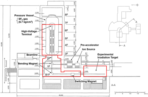
Figure 2. Schematic of the beam transport system. Faraday cup locations used to monitor the beam current are depicted as ‘FC-XX’ with a blue character and rectangle frame. Modified based on the original figure in ref [Citation13].
![Figure 2. Schematic of the beam transport system. Faraday cup locations used to monitor the beam current are depicted as ‘FC-XX’ with a blue character and rectangle frame. Modified based on the original figure in ref [Citation13].](/cms/asset/053c86f3-f7d4-4224-bac7-5918a004ba16/tnst_a_2313558_f0002_oc.jpg)
Experimental estimation of the beam loss during the accelerator operation
The experiment was performed for 24 hours beginning at 09:00 on 25 January 2018. Prior to beam operation, dose rate scanning was conducted with NaI survey meters (Hitachi, TCS-172B) for all beamlines in parallel with the passive detector installations. From 17:00, the beam was operated with 30 MeV of protons. Initially, the section beam loss amount along the whole beamline was estimated (). The beamline had ten Faraday cups (FC-01 to FC-10) along the way to confirm the beam current (). Beam currents were measured consecutively from FC-01 to FC-10 for one minute. The beam transmission rate was derived from the ratio of the average current of each Faraday cup to the current in FC-01. The beam operation for neutron fluence measurement continued for two hours, and the beam current was continuously monitored by FC-10 just before the final beam dump. The average beam current during the experiment was 247 nA. The initial current from the ion source was deduced as 770 nA. Approximately 30% of the current was lost before the pressure vessel inlet, 30% in the pressure vessel, and 10% in the bending magnet and switching magnet. Neutron generation should occur in these beam loss sites, including around the pressure vessel. The neutron dose monitors installed in the principal points in the facility; depicted as ‘N-dose monitor’ in , showed the 640 μSv/h (6F), 5.6 μSv/h (1F), 800 μSv/h (B1F, switching magnet room), and 12,800 μSv/h (B1F, irradiation room), as the average values during the beam operation.
Figure 3. Measurement points for the neutron fluence with the passive detectors and the γ-ray detectors are depicted over the horizontal cross sections of the facility. Constituent materials of the measurement points are described as hexagonal star (beamline or pressure vessel), triangle (floor concrete), and octagon (wall concrete). Color denotes the type of detection method: blue (γ-detector: LaBr3, Ge), green (passive detectors: gold foils, TLD, CR-39), and yellow (γ-detector and passive detectors). Lowercase alphabets were assigned to each measurement point as the location number.
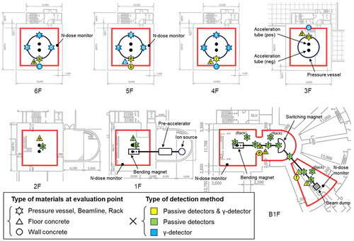
Table 1. Beam transmission rate between the faraday cups.
Measurement of the generated thermal neutron during the accelerator operation
For thermal neutron measurement, the 30 MeV proton beam operation was conducted for two hours from 20:25. This study employed two approaches to experimentally estimate the thermal neutron production during accelerator operation. One is the conventional method using passive detectors. The other is a new method using portable γ-ray detectors onsite to measure the thermal neutron amounts from the induced short-lived nuclides.
Ambient thermal neutron measurements with passive detectors
Conventional method for thermal neutron measurement using passive detectors are explained. Our experiment employed two types of dosimeters: a thermoluminescence detector (TLD) and a solid track detector (CR-39), and one activation detector (gold foils) were used as passive detector. overviews the installation points. The detector features are detailed below.
(1) Gold foil: This is an activation detector that uses the reaction of197Au(n,γ)198Au, which has a large cross section at the thermal energy region (98.7 b [Citation14]) and resonance integral region (1550 b [Citation14]). The measurement employed a gold foil of Φ6 mm and t0.02 mm. A pair of gold foils were installed at each point. One was sandwiched by a cadmium plate (t0.5 mm) with a large cross section in the thermal neutron region. The other was used as received, not sandwiched by a cadmium plate and any other materials. After neutron exposure, the activity of198Au produced in the gold foil was derived using a Ge detector, which is given as
The parameters are as follows: D is the specific activity of198Au (Dth and Dep produced by thermal and epi-thermal neutrons are expressed as Dth = Dwithout-Cd − Dwith-Cd and Dep = Dwith-Cd, respectively). S is the NET Area of the 412 keV photo peak for198Au. λ is the decay constant of198Au. Iγ is the branching ratio of 412 keV photons. η is the detection efficiency of the gold foil (Φ6 mm, t0.02 mm) calculated by ISOCS. w is the weight of the gold foil. t1 is the elapsed time from the beam stop to measurement start with the Ge detector. t2 is t1 + measurement time with the detector.
Thus, the average neutron fluence rate during the operation period is derived as
The parameters are as follows: Φ is the ambient neutron fluence rate (n/cm2/s). T is the beam operation period. σ is the cross-section of197Au. A thermal neutron capture cross section 98.7 b [Citation14] is used to calculate the thermal neutron fluence rate and resonance integral 1550 b [Citation14] is used to calculate the epi-thermal neutron fluence rate.
(2) CR-39: Commercially available solid-state track detectors (Nagase Landauer, Luminess Badge Service) were employed. As an after-support, the manufacturer analyzed the irradiated dosimeter and derived the value of neutron dose (convertible for the thermal neutron fluence). Thus, this technique is quite simple. Unlike gold foils, the analysis does not require special knowledge. Although the detector can record the fluence of both thermal (0.025 eV to 0.5 eV) and fast (24 keV to 15 MeV) neutrons separately. The manufacturer guarantees neutron measurements up to 50 mSv. CR-39 can be applied in the quite low neutron fluence field less than 101 n/cm2/s[Citation4].
(3) TLD: Commercially available detectors (Panasonic, UD813PQ4) were employed. A combination of6Li and10B phosphors, which are sensitive to thermal neutrons and γ-rays, and7Li and11B phosphors, which are sensitive only to γ-rays. Not only did this configuration enable specialized measurements of thermal neutrons, it is also applicable to low and high neutron fields due to its wide dynamic range. Irradiated dosimeters can be analyzed with a dedicated reader to obtain thermal neutron fluence semi-automatically. Unlike gold foils, the analysis does not require special knowledge. However, this system has two drawbacks. First, neutrons are difficult to measure in fields where γ-rays are too strong. Second, the manufacturer no longer handles new TLD, which adversely impacts availability.
For gold foils, the thermal neutron fluence rate during the experimental period was derived from the activity of198Au produced by neutron capture of197Au. Imaging plates were used to analyze some of the gold foils [Citation6,Citation8]. For TLD and CR-39, the measurement results were obtained as the thermal neutron fluence during the experimental period. The neutron fluence rate was derived by dividing the thermal neutron fluence by the beam operation time.
Onsite measurement for ambient thermal neutrons with γ-ray detectors
The thermal neutron fluence rate can be deduced from the activities of short-lived radionuclides; 24Na and56Mn, in the accelerator constituent materials. This method regards the accelerator components as a giant activation detector, by contacting a portable γ-ray detector on the material surface.
Neutrons generated during accelerator operation are eventually absorbed by the nuclei of the accelerator facility, producing radionuclides. In particular, the facility contains 55Mn and 23Na as impurities in the pressure vessel and concrete building. These impurities give rise to short-lived γ emitters of 56Mn and 24Na. The γ-rays of 56Mn (847 keV) and 24Na (1369 keV) from the pressure vessel and concrete surface were measured by using a portable 1.5-inch LaBr3 detector (Mirion Technologies, IPROL-1 (probe) and InSpector 1000 (multi-channel analyzer)) immediately after accelerator operation. Measurements were performed with focused on where the passive detectors were installed. Measurement times were from 60 s to 180 s per each point. The portable Ge detector (Mirion Technologies; GC2518) was used partially, at the same locations. Solely for the measurement with the Ge detector on the concrete floor, the 6.5 cm thick and 25 cm height lead shield was applied. This shield can suppress the background γ-ray noises 1/100 [Citation15]. Measurement times were from 300 s to 1800 s per each point.
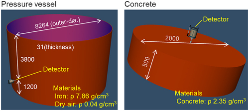
Similar to the gold foils, activities of 56Mn and 24Na were estimated from the spectra using Formula 1 by replacing the following parameters: D is the specific activity of 56Mn or 24Na. S is the NET area of 847 or 1369 keV photo peak. λ is the decay constant of 56Mn or 24Na. Iγ is the branching ratio of 847 keV or 1369 keV photons. Apparent shape of radiation sources were assumed considering the efficiency of the gamma-ray detector, as Φ8264 mm (outer diameter) × 5000 mm (height) × 31 mm (thickness) for pressure vessel, as Φ2000 mm (diameter) × 50 mm (depth) for concrete. η is the calculated detection efficiency for the pressure vessel or concrete. w is the weight of the radiation source, 3.151 × 10⁷ g for pressure vessel, and 3.691 × 10⁶ g for concrete. t1 is the elapsed time from beam stop to measurement start with the portable γ-ray detector. t2 is the t1 + measurement time with the γ-ray detector. The detection efficiencies were calculated assuming a radiation source for the pressure vessel and concrete using ISOCS [Citation16,Citation17] (). The calculation property of concrete was previously reported, and we confirmed the photon saturation for the source material [Citation3]. The number of neutrons (average thermal neutron fluence rate during accelerator operation) that contributed to the production of56Mn and24Na in the pressure vessel and concrete was derived from formula 2 by replacing the following parameters: σ is the thermal neutron capture cross section of 55Mn (13.3 b [Citation14]) or 23Na (0.531 b [Citation14]). The concentration of natMn in the SM490B, which is the rolled steel comprising the pressure vessel, was assumed as 0.01 g/g according to the JIS G 3136 [Citation18]. The concentrations for natMn or natNa in concrete were adopted as 0.00095 g/g [Citation2], and 0.021 g/g [Citation2], respectively.
Figure 4. Materials and dimensions for the detection efficiency calculation by ISOCS.
Results and discussion
Thermal neutron fluence rate during the accelerator operation
summarizes the measured thermal neutron fluence rates during the accelerator operation by each method. Black circles, triangles, and cross-marks indicate the neutron fluence rates measured with the gold foils, CR-39, and TLD, respectively. Although the gold foils were installed from the sixth to the 1st floor, the neutron exposure was too low to determine the thermal neutron fluence rate. The thermal neutron fluence rate of 101–103 n/cm2/s could be deduced using the gold foils placed in the switching magnet room on the first basement floor. In the irradiation room on the first basement floor, the thermal neutron fluence rate was about 104 n/cm2/s.
Figure 5. Thermal neutron fluence rate during the accelerator operation determined by passive detectors (gold foils, TLD, CR-39) and portable γ-ray detectors (LaBr3, Ge).
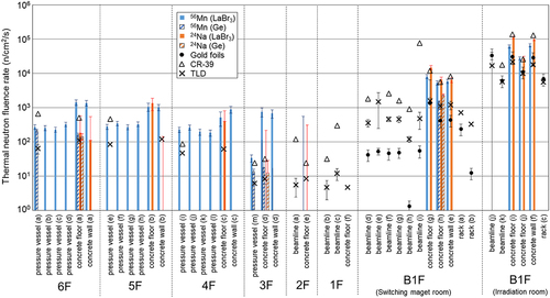
TLD could determine the thermal neutron fluence rate in all areas from the sixth floor to the irradiation room on the first basement floor. On the sixth to fourth floors, where the pressure vessel is located, the thermal neutron fluence rate was nearly constant at a value of approximately 102 n/cm2/s or less. On the third to first floors, the thermal neutron fluence rate was less than 101 n/cm2/s. This value was one order of magnitude smaller than that on the upper floors, suggesting a small beam loss. This was also deduced by the smaller neutron dose rate on the first floor compared to that on the sixth floor. The values in the switching magnet room on the first basement floor were approximately 103 n/cm2/s. These were slightly higher than those of the gold foils. By contrast, the values of 104 n/cm2/s for the irradiation room were almost the same as those of gold foils.
Overall, the CR-39 results were higher than the results of gold foils and TLD. CR-39 can detect neutrons in both the thermal and fast energy regions. The neutron dose was determined by the number of particle tracks recorded by the dosimeter. The contributions of the thermal and fast regions were derived by multiplying the correction factor to the neutron dose. There is a possibility that the correction factor is not optimized for the neutrons generated by beam losses in an accelerator, because the dosimeters were calibrated with neutrons from241Am-Be sources. Despite the uncertainties, CR-39 is a good candidate for measuring thermal neutrons during accelerator operation because unlike TLD, CR-39 has a stable supply chain and unlike gold foil, CR-39 does not require specialized knowledge for analysis.
The thermal neutron fluence rate on the beamline varied significantly, and some locations had more than two orders of magnitude differences among detectors. These are bigger than that of the concrete or pressure vessel surface. Thermal neutrons are produced by atomic collisions of beam loss neutrons with the air and structural materials such as concrete. Thermal neutrons on the beamline is few and distributed non-uniformly, thus the measurement of thermal neutron fluence rate with multiple detectors is challenging.
also shows the thermal neutron fluence rate estimated from56Mn (blue pillars) and24Na (orange pillars) activities produced in the pressure vessel and concrete. The filled symbols represent the results measured with the LaBr3 detector, while stripes represent the results measured with the Ge detector. The thermal neutron fluence around the pressure vessel could be measured in detail by taking advantage of the excellent mobility of the portable γ-ray detector.
On the sixth to fourth floor, the thermal neutrons around the pressure vessel were distributed uniformly in the room at approximately 102 n/cm2/s. These values overestimated the TLD results, and close to the CR-39 results. On the third floor, the values were about 101 n/cm2/s, an order of magnitude smaller than the upper floors. These results suggested a small beam loss. From sixth to third floor, the neutron fluence rates were higher on the walls and floor than on the pressure vessel, which is the neutron source. It is considered that 56Mn γ-rays from the pressure vessel would influence the measurement on the concrete. The contribution of 847 keV photons from the pressure vessel account for about half of the photons arriving at the detector during the measurement at the concrete wall was found by calculation using ISOCS. In addition, of the 6 surfaces that make up the room (4 walls, 1 floor, and 1 ceiling), the contribution from the 5 surfaces other than the subject surface is 20% to 30%. Determining the thermal neutron fluence rate using the LaBr3 detector was challenging under 101 n/cm2/s or less, due to insufficient statistics. Background noises attribute to γ and β rays from138La, which is a natural radioactive isotope, cannot be avoided in the γ-ray spectrometry with a LaBr3 detector. Especially on the measurement with a low activity target, the influence of background noises is relatively large, challenging to quantify the radioactivity accurately. In such conditions, the use of CeBr3 or Ge detectors can eliminate the background noises from self-activities. In the switching magnet room on the first basement floor, the thermal neutron fluence rate ranged from 103–104 n/cm2/s. In the irradiation room, the values were the order of 104 n/cm2/s. These values were comparable within the one to two orders of magnitude to the results of gold-foils, TLD and CR-39. The results of the Ge-detector with the lead shield; concrete floor (a), (d), and (h), were corresponded to the thermal neutron fluence of TLD, respectively. These results reproduced the results of previous study [Citation2]. Applying the lead shield, measurement comparable to the TLD, can be performed among the order of 101 to 103 n/cm2/s. In addition to passive detectors, the proposed method using portable γ-ray detectors should be useful for neutron fluence measurement in accelerator facilities.
Accumulated activities in the future decommissioning work
The accumulated activities produced continuously in the facility over 50 years can be deduced from the result of thermal neutron fluence generated during the beam operation. The results of activation assessment during the decommissioning at a cyclotron facility, it was revealed that 60Co and 152Eu account for the almost of 80% of the residual radionuclides [Citation19]. As the beam energy is similar to the JAEA-tandem accelerator, it is assumed that 60Co and 152Eu are the main nuclides for activation.
The annual accelerator operations were estimated as follows. First, the average beamtime during the 12-year period from 2011 to 2022 was 125.3 days. Among them, 24.4 days were for experiments with light ions; p, He, and Li, which contribute to activation. Therefore, 24.4 days of annual operation was adopted for 6F and B1F (Switching magnet room). The annual usage time of the irradiation room based on the 11 years of actual use history was 15.3 days. It was assumed that the accelerator was operated continuously in 24 hours a day during the period with a 30 MeV proton beam.
The averages of 6F, B1F switching magnet room, and B1F irradiation room for LaBr3 of 270, 7870, and 66,280 n/cm2/s, respectively, were employed as irradiation neutrons. The concentrations of stable isotopes of natCo and natEu in the concrete were adopted as 8 μg/g, and 0.7 μg/g, respectively, from our previous study on neutron activation analysis for accelerator shielding concrete [Citation20]. Because there is no control value for the Co concentration of SM490B which is the rolled steel comprising the pressure vessel, 32 μg/g was adopted as the natCo concentration tentatively. This is the value of high purity iron purchased from Alfa Aesar [Citation21]. Natural abundance of 59Co and 151Eu are 1.000 [Citation22], and 0.4781 [Citation22], respectively.
summarizes the results. The accumulated activities of 60Co and 152Eu were nearly saturated in 20 years and 40 years, respectively. In the case of the pressure vessel, the maximum 60Co production amount was 0.0002 Bq/g. Because this is less than 1/500 of the clearance level (0.1 Bq/g), the activation is negligible, even in long-term operations. The sum of the production activities for 60Co and 152Eu in the switching magnet room was 0.005 Bq/g. Because both nuclides had clearance levels of 0.1 Bq/g, the deduced value is sufficiently low. Thus, activation is also negligible in this area. The sum of the production activities for 60Co and 152Eu in the irradiation room was 0.029 Bq/g, which is 30% of the clearance level. Depending on the operation conditions, activation cannot be negligible in this area. The activation/non-activation of concrete materials in the irradiation room should be investigated when the facility is decommissioned. However, this estimation is based on a safety-conscious approach and assumes longer operating times than in practice. This facility can accelerate a variety of ion species, and many users utilize other types of beams. In the case of heavy ion acceleration, the Coulomb barrier prevents nuclear reactions and such beams should not contribute to activation.
Table 2. Accumulated induced activities in the pressure vessel and concrete (Bq/g).
Measurement for beamline and identification of induced activities
In parallel with the neutron measurements, dose rate scanning with NaI survey meters was performed for all beamlines. Additionally, γ-ray spectrometry was conducted for representative points where high-dose were identified. shows the dose-rate scanning results for beamlines before (12:00–15:00 on 25 January 2018) and after the beam operation (23:00 on 25 January 2018–3:00 on 26 January 2018). Most high-dose sites were Faraday cups. It was suggested that beam current monitoring at the experiment’s beginning influenced to generation of short-lived nuclei. The main nuclides contributing to the dose rate might be56Mn. High doses were observed before the beam operation at the Faraday cup (FC-07) on the first floor, the bending magnet’s entrance, and the switching magnet’s entrance on the basement floor. Several radionuclides assumed to be derived from W were identified, all with short half-lives of less than one year.
Figure 6. Results of contact dose-rate measurement for beamline components (μSv/h) performed before (B/O) and after the beam operation (A/O). The results include the background dose of 0.04 μSv/h.
Conclusion
The thermal neutron fluence generated during the accelerator operation was measured experimentally at the JAEA-Tokai tandem accelerator facility; world’s highest terminal voltage of electrostatic accelerator. Conventional methods using passive detectors (dosimeters for environmental dose measurement and metal foil detectors) as well as a new method using a portable γ-ray detector were adopted for the measurement on the pressure vessel, concrete building, and beamline. The amounts of produced thermal neutrons in the facility during accelerator operation ranged from 101 n/cm2/s to 104 n/cm2/s. Due to the excellent mobility of portable γ-ray detectors, the thermal neutron fluence during the beam operation around the pressure vessel could be investigated in detail. Our experimental results showed that the combination of CR-39 and on-situ measurement with γ-ray detectors can provide a safety-conscious approach in the activation assessment and can be a substitute for TLD which has crucial problem in the supply chain. From the thermal neutron fluence measurement results, accumulated activities of 60Co in the pressure vessel and 60Co and 152Eu in the concrete building in 50 years were deduced. Except for the irradiation room where the thermal neutron fluence rate was on the order of 104 n/cm2/s, activation is negligible in this facility. From the dose-rate scanning of beamlines, we found that the Faraday cups, which were used to monitor the beam current in the experiment, showed high dose.
Acknowledgments
We thank the Radiation Safety Research Promotion Fund “Clearance of materials from the decommissioning of accelerator facilities” by the Japan Nuclear Regulation Authority for their support.
Disclosure statement
No potential conflict of interest was reported by the author(s).
Additional information
Funding
References
- ICRP Publication 107. Nuclear decay data for dosimetric calculations. Ann ICRP. 2008;38(3).
- Matsumura H, Yoshida G, Toyoda A, et al. Nondestructive high-sensitivity measurement method for activation estimation in accelerator room concrete. Radiat Prot. 2020;40(6):677–682.
- Matsumura H, Yoshida G, Toyoda A, et al. Investigation of concrete radioactivation in cyclotron type proton therapy facilities using in situ 24Na measurement method. Radiat Saf Manag. 2022;21:13–25. doi: 10.12950/rsm.200909
- Yoshida G, Matsumura H, Masumoto K, et al. Investigation into activation of accelerators at various synchrotron radiation facilities in Japan. J Nucl Sci Technol. 2022;59(5):543–554. doi: 10.1080/00223131.2021.1985646
- Masumoto K, Matsumura H, Bessho K, et al. Role of activation analysis for radiation control in accelerator facilities. J Radioanal Nucl Chem. 2008;278(2):449–453. doi: 10.1007/s10967-008-0902-5
- Toyoda A, Matsumura H, Masumoto K et al. Quantitative evaluation of radioactivity in concrete at PET cyclotron facility with simple and non-destructive measurement. Environ Radiochem Anal. 2019;VI:178–183. doi: 10.1039/9781788017732-00178
- Nakamura H, Matsumura H, Yoshida G et al. Investigation of neutron-fluence measurement methods for estimating neutron-induced activity from an electrostatic accelerator source. Environ Radiochem Anal. 2019;VI:152–160. doi: 10.1039/9781788017732-00152
- Masumoto K, Toyoda A, Eda K et al. Measurement of the spatial distribution of neutrons in an accelerator room by the combination of activation detectors and an imaging plate. Radiat Saf Manag. 2002;1(1):12–16. doi: 10.12950/rsm2002.1.12
- Yoshida G, Matsumura H, Nakamura H et al. Survey methodology for the activation of beamline components in an electrostatic proton accelerator. Radiat Saf Manag. 2021;20:1–8. doi: 10.12950/rsm.200813
- Matsumura H, Yoshida G, Toyoda A et al. Simplified method for determining residual specific activity in activated concrete of a PET-Cyclotron room using a survey meter. Environ Radiochem Anal. 2019;VI:135–147. doi: 10.1039/9781788017732-00135
- Masumoto K, Matsumura H, Miura T, et al. Evaluation of activated area in the electrostatic accelerator facilities. Full Paper ISORD10, 2020.
- Matsumura H, Matsumura M, Yoshida G, et al. Gamma-ray measurements inside the acceleration tank of the 6MV tandem electrostatic accelerator at the University of Tsukuba. UTTAC Annual Report 2022. 2023.
- Tandem accelerator reactor department of research and tandem accelerator section, JAEA-Tokai Tandem accelerator web page. [cited 2023 Sep 4]. Available fom: https://ttandem.jaea.go.jp/koumoku-02/kasokuki.html
- Shibata K, Iwamoto O, Nakagawa T, et al. JENDL-4.0: a new library for nuclear science and engineering. J Nucl Sci Technol. 2011;48(1):1–30. doi: 10.1080/18811248.2011.9711675
- Yoshida G, Matsumura H, Nishikawa K, et al. In-situ evaluation for activated concrete in accelerator facility with scintillation-type gamma-ray spectrometer. Radiat Prot. 2020;40(6):545–549.
- Venkataraman R, Bronson F, Atrashkevich V, et al. Improved detector response characterization method in ISOCS and LabSOCS. J Radioanal Nucl Chem. 2005;264(1):213–219. doi: 10.1007/s10967-005-0696-7
- Bronson FL. Validation of the accuracy of the LabSOCS software for mathematical efficiency calibration of Ge detectors for typical laboratory samples. J Radioanal Nucl Chem. 2003;255(1):137–141. doi: 10.1023/A:1022248318741
- Japanese Industrial Standards. JIS G 3136: Rolled steels for building structure; 2012.
- Matsumura H, Toyoda A, Masumoto K, et al. In-situ determination of residual specific activity in activated concrete walls of a PET-Cyclotron room. J Phys Conf Ser. 2018;1046(1). doi: 10.1088/1742-6596/1046/1/012016
- Yoshida G, Nishikawa K, Nakamura H, et al. Investigation of variations in cobalt and europium concentrations in concrete to prepare for accelerator decommissioning. J Radioanal Nucl Chem. 2020;325(3):801–806. doi: 10.1007/s10967-020-07212-7
- Klueh RL, Cheng ET, Grossbeck ML, et al. Impurity effects on reduced-activation ferritic steels developed for fusion applications. J Nucl Mater. 2000;280(3):353–359. doi: 10.1016/S0022-3115(00)00060-X
- Benner SA, Battersby TR, Eschgfaller B et al. Redesigning nucleic acids. Pure Appl Chem. 1998;70(2):263–266. doi: 10.1351/pac199870020263