
 ?Mathematical formulae have been encoded as MathML and are displayed in this HTML version using MathJax in order to improve their display. Uncheck the box to turn MathJax off. This feature requires Javascript. Click on a formula to zoom.
Abstract
Building on our previous work on NO + Ar, this paper presents a complete set of orientation measurements and quantum mechanical calculations for the NO + Kr collision system, including both spin-orbit conserving and changing collisions, and both side-on (x-axis) and end-on (z-axis) orientations. While many of the trends observed in the oriented differential and integral scattering distributions, as well as in the spin-orbit branching fractions, are similar to the ones seen previously for NO + Ar, a direct comparison with the Ar data reveals subtle differences in the scattering dynamics, which we rationalise with the more extended attractive regions on the NO + Kr potential energy surfaces. High-impact parameter collisions that lead to low scattering angles in the spin-orbit conserving manifold are particularly sensitive to the topology in the attractive parts of the potential, whereas more impulsive, low-impact parameter trajectories, which sample the repulsive parts of the potential, produce very similar features in the oriented differential cross sections for the Ar and Kr systems, especially for spin-orbit changing collisions.
GRAPHICAL ABSTRACT

1. Introduction
The stereodynamics of molecular processes provide valuable information on what conformation or relative geometry promotes a certain chemical change within a system, or, conversely, most efficiently prevents an undesired reaction from happening. These processes are determined by the electronic structure of the molecular system under study, which can be described theoretically by a single or multiple coupled potential energy surfaces (PESs) [Citation1–3]. Because of its importance in nature, stereodynamics is a broad field of research, ranging from gas-phases studies of atoms and small molecules [Citation4–7] to investigations of binding mechanisms in proteins in solution [Citation8–10]. As broad as the research field itself are the methods with which orientational effects are studied. Semi-classical and quantum mechanical approaches are used in calculations of the product distributions [Citation2, Citation3, Citation11–13], while optical [Citation14–17], magnetic [Citation18, Citation19], and electric [Citation4, Citation5, Citation7, Citation20, Citation21] field methods are applied to experimentally align or orient molecules and atoms prior to reaction.
Electric field orientation has been used in a variety of gas phase experiments since the 1970s. Brooks and Jones, as well as Beuhler, Bernstein, and Kramer, first showed that symmetric [Citation4, Citation5, Citation22] and asymmetric [Citation23] top molecules could be oriented in a static electric field after transmission through the inhomogeneous field of a hexapole. Since then, different groups have used variations of this methodology to orient linear, symmetric, and asymmetric tops such as CDI [Citation6], OH [Citation7], SO [Citation18], and NO [Citation21]. Following on from work by Stolte and coworkers [Citation21, Citation24–26], our group has combined hexapole state selection with electric field orientation to study the stereodynamics of Ar atoms colliding with end-on [Citation27–30] and, more recently, side-on [Citation31–33] oriented NO molecules. In the current work, we extend these studies to collisions of oriented NO molecules with Kr atoms to investigate the effect the increased mass and the higher polarisability of the rare gas atom (compared to Ar) has on the orientation dependence of the scattering dynamics. We present an exhaustive set of velocity-map ion images and compare the extracted differential cross sections (DCSs), integral steric asymmetries (ISAs), and spin-orbit branching fractions with quantum mechanical (QM) calculations. The QM calculations make use of our recently developed treatment which enables evaluation of the relevant quantities at any arbitrary orientation [Citation31, Citation32].
Orientation in a static electric field requires the diatomic molecule of interest to possess a permanent electric dipole moment and to be open-shell (assuming only first-order Stark effects are important) [Citation34]. In its ground electronic state, the NO molecule has a small dipole moment of 0.1574 D [Citation35] and an unpaired electron in its orbital, making it a
system with two distinct spin-orbit manifolds. The two spin-orbit manifolds are defined by the spin-orbit quantum number,
, the absolute value of the sum of the projections of the spin (
) and electronic orbital angular (
) momenta onto the internuclear axis. The ground and excited spin-orbit manifolds corresponds to
and
, respectively. Within each spin-orbit manifold, the rotational states are further split into two Λ-doublet levels, which are the symmetric and antisymmetric combinations of the
and
wavefunctions (where m is the projection of
, the total rotational angular momentum excluding nuclear spin, onto the relative velocity vector,
) [Citation36]. These symmetric and antisymmetric states are distinguished by their respective symmetry indices
(e state) and
(f state) [Citation37].
The small dipole moment of NO necessitates relatively high experimental field strengths to properly orient the molecules. However, even at a hypothetical field strength of infinity, the degree of orientation is limited by a broad cosine probability distribution [Citation27]. In our experiments, we select the low-field seeking f Λ-doublet of the ground rotational state, which will orient antiparallel to the direction of the electric field, as the molecular dipole moment,
, points from the N-end to the O-end [Citation38]. Within the electric field, the selected f state will evolve into a superposition state with contributions from both Λ-doublet levels [Citation21, Citation24, Citation39]:
(1)
(1)
where
is the projection of
onto the electric field vector
, and α and β are the field-dependent mixing parameters defined elsewhere [Citation21, Citation24]. At the experimental field strength used in the present work,
and
take on values of 0.64 and 1.26, respectively [Citation27].
Since the electric field vector defines the orientation of the molecules, it is convenient to specify the different orientations by the polar () and azimuthal (
) angles of the associated field vector in the scattering frame. This is illustrated in Figure (a). In the scattering frame, the z-axis is parallel to
, which we define as
. The xz-plane coincides with the
plane (where
is the outgoing relative velocity vector), and the y-axis is chosen such that the frame is right-handed. The angle between
and
is the scattering angle θ.
Figure 1. Definition of the electric field vector in the scattering frame (a) and example velocity-map ion images for the final rotation state in the N-side (b) and N-end (c) orientations. The scattering frame's z-axis is defined parallel to the initial relative velocity vector,
, and the x-axis is defined by the
plane, where
is the final relative velocity vector after collision and indicates the direction of the outgoing Kr atom. The angle between
and
is the scattering angle θ, and
(green arrow) and
(brown arrow) are the initial velocities of the NO and Kr beams in the laboratory frame. Note that the NO molecules (green dotted arrow in (b) and (c)) scatter in the direction opposite to
. The electric field,
, is created by a set of positively and negatively charged rods, which preferentially orient the NO molecules with their dipole moment (N
O) antiparallel to
. For side-on orientation (b), the rods are oriented parallel to
, for end-on orientation (c), the rods are oriented perpendicular to
.
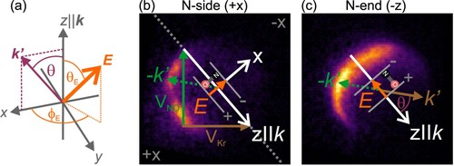
Figure (b,c) show two example velocity-map ion images recorded for the final state in the N-side and the N-end orientations. The Newton diagram, showing the initial velocity vectors of the NO (green) and Kr (brown) beams, respectively, as well as
, which is overlaid with the scattering frame's z-axis, is depicted in the side-on image in panel (b). An example outgoing relative velocity vector (brown arrow) and the corresponding velocity vector of the scattered NO (
, green dotted arrow) are indicated in the N-end image in panel (c). For the end-on orientation, scattering is symmetric around
, making the
angle redundant. The electric field vector,
, in the N-end image points along the
direction (
, with
(N
O) antiparallel to it). When the polarity is switched, the orientation will become O-end, with
pointing along the
-axis (
). For the side-on orientation, in which
is directed perpendicular to the z-axis (and along the x-axis), scattering is no longer symmetric around
and the orientations are opposite in the two halves to the left and right of
(indicated by the grey dotted line). NO scattering towards the upper right side of the image (the ‘fast’ side in the laboratory frame) corresponds to
orientation (O-side,
, indicated by the grey
label in the figure), while scattering towards the lower left side (the ‘slow’ side in the laboratory frame) corresponds to
(N-side,
, indicated by the grey
label in the figure) orientation of the electric field vector. When switching the polarity of the field, the orientations in the two halves of the image will be inverted. Note that the correspondence between
and the N-side(O-side) orientation implies near-side scattering, which is strictly the case for medium and high rotational excitations. For far-side scattering,
corresponds to the O-side(N-side) orientation.
2. Methods
2.1. Experimental methods
The crossed-molecular beam apparatus used to record velocity-map ion images of the rotationally excited NO molecules following collision with Kr atoms has been described in detail previously [Citation27, Citation32]. Briefly, a mixture of about 15% NO and 85% Ar was expanded in a skimmed supersonic molecular beam and passed through a hexapole state selector, which focussed the low-field seeking f Λ-doublet state into the centre of the scattering chamber. There, the molecules were oriented in a static electric field of 9.2 kV/cm and crossed with a pure Kr atomic beam at right angles, resulting in a mean collision energy of 612 cm. The skimmed Kr beam was fired at 5 Hz, half the frequency of the NO beam, to allow for active background subtraction of unscattered NO signal. Following collision with the Kr atoms, the rotationally excited NO molecules (in either of the two spin-orbit manifolds) were state-selectively detected using a (1+1
) Resonance Enhanced Multiphoton Ionisation (REMPI) scheme [Citation40]. The resonant photon near 226 nm was produced by a tunable dye laser, while the (non-resonant) ionisation photon was provided by the 308 nm fundamental of a XeCl excimer laser. The horizontally polarised probe laser beam entered the scattering chamber approximately perpendicular to the relative velocity vector,
, while the unpolarised 308 nm ionisation beam propagated roughly antiparallel to
. The NO ions were subsequently velocity-mapped [Citation41, Citation42] onto a dual MCP/phosphor screen detector and the ion signal recorded with an intensified charge-coupled device camera.
The orientation field was created by a set of four rods, with the two rods on either side charged to ±8 kV. Within the electric field, the dipole moment of the NO molecule will orient such that the N-end preferentially points towards the negatively charged electrodes, and the O-end towards the positively charged electrodes [Citation38]. Thus, for end-on collisions, the rods were oriented perpendicular to the relative velocity vector, whereas for collisions of the Kr atom on the side of the molecule, the rods were placed parallel to (see Figure (b,c)). During an experiment, the polarity of the rods was switched every 200 laser shots, such that the two end-on/side-on orientations were probed alternatingly and the effect of experimental drift on the measurement was minimised. Typical ion images were accumulated over 60,000–100,000 laser shots (including background counts), until convergence was achieved.
2.2. Theoretical methods
Quantum mechanically, collisions of an NO molecule with a rare gas atom take place on two coupled PESs, which are characterised by the position of the unpaired electron with respect to reflection in the plane defined by the NO molecule and the rare gas atom of interest. If the unpaired electron of the molecule lies within the triatomic plane, the symmetry label is A; if the unpaired electron lies perpendicular to the triatomic plane, the symmetry label is A
. Following the work by Alexander [Citation1, Citation43, Citation44], the full PES can be expanded as the half sum and half difference of the adiabatic A
and A
potentials:
(2)
(2)
and
(3)
(3)
where R is the distance between the rare gas atom and the centre of mass of the NO molecule, and γ describes the angle between R and the molecular bond axis, r. The
terms are the radially dependent expansion coefficients and the
terms are reduced Wigner rotation matrix elements [Citation36]. For Hund's case (a) molecules, spin-orbit conserving transitions can be described well by the sum potential only, while for spin-orbit changing transitions, the off-diagonal matrix elements of the difference potential are necessary for an adequate description of the scattering dynamics [Citation44].
The differential cross sections (DCSs) for NO() + rare gas collisions with a well defined initial relative orientation can be expressed in terms of the r-polarisation moments (r-PDDCSs) [Citation31, Citation32],
(4)
(4)
Here, the
moment is the isotropic polarisation moment, and the
and
moments describe the polarisation along the scattering frame's z- and x-axes, respectively [Citation45].
is the isotropic integral cross section in the presence of the electric field, equivalent to orientation along the scattering frame's y-axis. The electric field vector is defined by
and
(see Figure (a)), and α and β are the field-dependent mixing coefficients introduced earlier.
The moments themselves are proportional to products of the scattering amplitudes for the field-free
and
transitions [Citation31, Citation32],
(5)
(5)
(6)
(6)
(7)
(7)
where
(8)
(8)
and
and
are the scattering amplitude and its conjugate complex for the specified
transition, with m and
the projections of j and
onto the relative velocity vector,
, and ϵ and
the initial and final Λ-doublet states.
The integral cross section (ICS) can be obtained by integrating the DCS for a given orientation over (the ICS represents the integrated cross section within the collision plane). The normalised differences between the ICSs for the two side-on (
) and the two end-on (
) orientations define the integral steric asymmetries (ISA),
and
, respectively [Citation21]:
(9)
(9)
(10)
(10)
With these definitions, and assuming only near-side scattering, positive values of
and
correspond to N-side and N-end preferences, respectively, while negative values indicate a preference for O-side and O-end conformations. In a recent publication, we have shown that the ICS for an arbitrary orientation can also be calculated from the ISAs for the side-on and end-on orientations [Citation46] according to
(11)
(11)
The ICSs for the spin-orbit conserving (
) and changing (
) transitions of a given final rotational state, at a given initial orientation, can then be used to calculate the spin-orbit branching fraction, which we define as follows:
(12)
(12)
2.3. Computational details
Close-coupled quantum mechanical (CC-QM) calculations on the NO + Kr PESs by Wen et al. [Citation47] were performed using the Hibridon suite of codes [Citation48]. The calculations were propagated from 4.5 bohr to 65.0 bohr, using the log-derivative propagator [Citation49]. 260 partial waves and a rotational basis with states up to , including both spin-orbit manifolds and both Λ-doublet levels, were used to ensure convergence. The calculations were run over the spread of the experimental collision energy, assuming a Gaussian distribution with a mean collision energy of
and a full width at half maximum of 25 cm
. Polarisation moments and differential cross sections for the two side-on and the two end-on orientations were calculated for all energetically accessible states, in both the spin-orbit conserving (
) and the spin-orbit changing (
) manifolds. For the theoretical analysis, the DCSs for the different NO orientations were calculated at infinite field strength on the A
, A
, sum, and full potentials separately.
For comparison purposes, calculations were also run for the NO + Ar and NO + He systems, employing the PESs of Alexander [Citation2, Citation50] and Yang and Alexander [Citation51], respectively.
2.4. Data analysis
The DCSs of the rotational states probed in the experiment were extracted from the corresponding velocity-map ion images according to the procedure outlined in our earlier work on the NO + Ar collision system [Citation32]. First, the experimental images were simulated using a Monte Carlo method with the various experimental parameters, including the spatial, temporal, and velocity spreads of the molecular beams, as well as the widths and timings of the laser beams, defining the sample region. In this manner, the instrument function and polarisation dependent correction factor could be established and were convolved with a set of spherical harmonics basis functions to reproduce the experimental images as closely as possible. The polarisation correction, which was estimated using the apse model [Citation52, Citation53], incorporates the collision-induced alignment of the ions detected with horizontally polarised laser light.
Due to the presence of the orientation rods in the velocity mapping field, the images are slightly elongated along the axis of the rods (parallel to for x-axis orientation, perpendicular to
for z-axis orientation; see Figure ). This effect was accounted for by fitting ellipses to the experimental images and stretching the basis functions accordingly. The ratio of the short and long axis of the ellipses was kept constant for states probed with the same laser position and was scaled according to the outgoing velocity of each state. The generated basis functions were then used to fit the sum and difference images for the two orientations and extract the isotropic polarisation moment,
, and either the
(end-on orientation) or the
(side-on orientation) moment. These moments were substituted into Equation (Equation4
(4)
(4) ) to determine the DCSs.
3. Results and discussion
3.1. Velocity-map ion images and DCSs
The experimental velocity-map ion images for the x-axis and z-axis orientations, in both spin-orbit manifolds, are shown in Figures . The N-side(N-end) and O-side(O-end) orientations are shown in the first and second column, and the experimental and simulated difference images are shown in the third and fourth column, respectively. The difference images were obtained by simply subtracting the image from the
image (side-on orientation), and the
image from the
image (end-on orientation), respectively. The fifth and sixth column in the figures compare the DCSs extracted from the experimental images (blue lines) with the QM calculated DCSs (red dashed lines) for the two sides/ends.
Figure 2. NO + Kr velocity-map ion images for the and
orientations (first and second column), experimental and simulated difference images (third and fourth column), and
and
differential cross sections (fifth and sixth column) for the spin-orbit conserving manifold. The experimental DCSs are shown in blue, with error bars representing one standard deviation; the QM DCSs, which have been averaged over the collision energy distribution, are shown in red. The insets in the
DCSs for
and
show an enlarged view of the ℓ-type rainbow in the
region. The direction of the relative velocity vector,
, is indicated in the top left image.
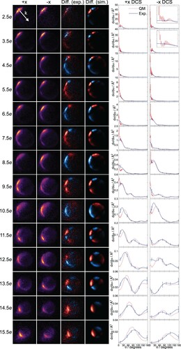
Figure 3. NO + Kr velocity-map ion images for the and
orientations (first and second column), experimental and simulated difference images (third and fourth column), and
and
differential cross sections (fifth and sixth column) for the spin-orbit changing manifold. The experimental DCSs are shown in blue, with error bars representing one standard deviation; the QM DCSs, which have been averaged over the collision energy distribution, are shown in red. The direction of the relative velocity vector,
, is indicated in the top left image.
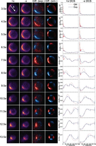
Figure 4. NO + Kr velocity-map ion images for the and
orientations (first and second column), experimental and simulated difference images (third and fourth column), and
and
differential cross sections (fifth and sixth column) for the spin-orbit conserving manifold. The experimental DCSs are shown in blue, with error bars representing one standard deviation; the QM DCSs, which have been averaged over the collision energy distribution, are shown in red. The inset in the
DCS for
shows an enlarged view of the ℓ-type rainbow in the
region. The direction of the relative velocity vector,
, is indicated in the top left image.
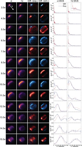
Figure 5. NO + Kr velocity-map ion images for the and
orientations (first and second column), experimental and simulated difference images (third and fourth column), and
and
differential cross sections (fifth and sixth column) for the spin-orbit changing manifold. The experimental DCSs are shown in blue, with error bars representing one standard deviation; the QM DCSs, which have been averaged over the collision energy distribution, are shown in red. The direction of the relative velocity vector,
, is indicated in the top left image.
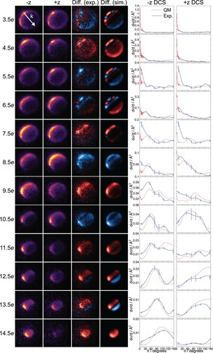
In general, the experimental and simulated difference images are in very good agreement and the experimental DCSs match up well with the QM calculations. There are some discrepancies, particularly in the forward scattered region (), where glancing collisions dominate. In this region, both near-side (repulsive) and far-side (attractive) trajectories are possible, with the latter allowing for ℓ-type rainbow scattering, as observed in unoriented NO + Kr collisions [Citation54, Citation55]. An ℓ-type rainbow (where ℓ refers to the nuclear orbital angular momentum) corresponds to a secondary maximum in the (classical) deflection function, characterised by a low scattering angle and a high impact parameter [Citation12, Citation56, Citation57]. In the current calculations, the rainbow is predicted particularly prominent in the
orientation for
and in the
and
orientations for
in the spin-orbit conserving manifold (see insets in Figures and ). These orientations correspond to repulsive collisions of the approaching Kr atom off the O-side and O-end, respectively; however, since the trajectories responsible for the rainbow are expected to proceed along the far side, the initial orientation for the
trajectories is in reality N-side, but instead of scattering off the N-side, the Kr is pulled around towards the O atom. In the
orientation, the Kr atom approaches from the O-end, passes the molecule on the side, and is then pulled over to the far side at the N-end. This interpretation is supported by the presence of an attractive well at the N–end (but not at the O–end) of the NO molecule for the Vsum PES of the NO + Kr system (see right column in Figure ), which may guide trajectories towards the other side. Experimentally, our resolution is not quite sufficient to fully resolve the rainbow, although the DCSs extracted from the experiment roughly reproduce the extent of the calculated rainbows. The differences between the experimental and computational DCSs may also be partly due to small inaccuracies in the PESs used for the calculations [Citation47].
For higher lying final states, for which the scattering distributions become broader and more backward scattered, the experimental resolution is less of a limiting factor and far-side scattering becomes highly unlikely [Citation33]. In addition to the increasingly backward scattered DCSs, the Newton spheres of the scattered NO molecules become smaller as increases, since more of the initially available energy is converted into rotational, and consequently less into translational, degrees of freedom.
The experimental DCSs for the spin-orbit changing transitions exhibit overall poorer agreement with the QM calculated DCSs. This is mainly a detection issue, as the signal is typically lower for the spin-orbit changing transitions and the structures in the scattering distributions less pronounced, both of which make fitting more challenging. Moreover, if there are indeed shortcomings in the modelled potentials, the spin-orbit changing transitions would likely be more susceptible to them, since they largely depend on the difference potential , which has been suspected to be less accurate than the
potential [Citation47]. This, in turn, could also contribute to the poorer agreement between experiment and theory.
As observed previously for NO + Ar [Citation27, Citation30–33], the orientational preferences of the DCSs alternate between even and odd transitions. This is readily seen in the difference images in Figures –, where red indicates a positive and blue a negative intensity. A positive intensity corresponds to a preference for the
orientation, while a negative intensity corresponds to a preference for the
orientation. Note that for the x-axis orientation, the difference images are inversely symmetric around
, whereas the difference images for the z-axis orientation are symmetric around
. In the x-axis orientation, scattering to the left and right of
correspond to N-side and O-side collisions in the
image and vice versa in the
image. A negative/positive intensity on the fast side of the image (to the right of
) therefore corresponds to a preference for the
orientation. Overall, even states are found to be dominated by scattering towards the O-side/O-end (
) and odd states by scattering towards the N-side/N-end (
) of the NO molecule.
The DCSs for intermediate
transitions (
in the spin-orbit conserving and
in the spin-orbit changing manifold) generally exhibit two main features, while the
DCSs typically only show one main peak. Similar trends were observed in QM calculations of the DCSs for NO + Ar at infinite field [Citation31], where it was shown that interference between trajectories at the N-side and the N-end lead to more features, and more forward scattering, than interference between trajectories at the O-side and the O-end. Due to the lower mass of the N atom, trajectories of the rare gas atom towards the N-side/N-end can induce rotational excitation at larger impact parameters, resulting in more forward scattered cross sections with more maxima. Since these characteristics pertain to the NO molecule rather than the rare gas, the same argument also holds for NO + Kr.
3.2. Integral steric asymmetries
The four panels in Figure quantify the extent of orientational preference in terms of the integral steric asymmetry, as defined in Equations (Equation9(9)
(9) ) and (Equation10
(10)
(10) ). The ISAs for the end-on and side-on orientations are shown on the left- and right-hand side of the figure, with the spin-orbit conserving (
) and changing (
) manifolds at the top and bottom, respectively. As for the DCSs, the agreement between experiment (shown in blue, with error bars representing one standard deviation) and theory (shown in red) is overall very good.
Figure 6. NO + Kr experimental and QM integral steric asymmetries for the end-on (left) and side-on (right) orientations in the spin-orbit conserving (, top) and changing (
, bottom) manifolds. Error bars in the experimental data (blue) correspond to one standard deviation. The QM data (red) have been averaged over the experimental collision energy distribution.
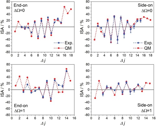
In both orientations, the spin-orbit conserving manifold shows clear oscillations between even and odd states in the intermediate region, covering a range between −48% and 34%. We have explained these trends in a quantum mechanical picture in which the sign of the phase shift between interfering trajectories changes as a function of final rotational state [Citation31, Citation32]. For rotational excitations above
, N-side/N-end collisions are consistently preferred over O-side/O-end collisions, indicating the classical regime, in which a higher torque can be exerted near the (lighter) N-end of the molecule, thus facilitating access to highly excited rotational states. The oscillations in the ISA for the spin-orbit conserving manifold are roughly centred around 0, with a slight shift towards negative values. This shift is due to unequal mixing of the initial e and f Λ-doublets at the experimental field strength, which leads to a small overall O-side/O-end preference for final e states (and a small overall preference for N-side/N-end collisions for final f states) [Citation32]. Calculations carried out at infinite field show that the shift essentially disappears [Citation32].
The spin-orbit changing collisions exhibit an overall preference for positive ISAs, that is, a preference for N-side/N-end collisions. We have observed the same trend in our previous work on the NO + Ar system, in which we attributed the N-side/N-end preference to the location of the unpaired electron closer to the N atom of the molecule [Citation33]. Since the incoming rare gas atom can more efficiently interact with the unpaired electron at shorter distances, a change in spin-orbit quantum number is more likely to occur for collisions towards the N-side/N-end. In addition, the oscillations of the ISA between even and odd transitions are less pronounced in the spin-orbit changing collisions, and the DCSs for the two side-on and the two end-on orientations are somewhat more similar than in the spin-orbit conserving collisions (see Figures –).
3.3. Spin-orbit branching fractions
The spin-orbit branching fractions, which can be calculated straightforwardly from the ISAs for the side-on and end-on orientations (Equations (Equation11(11)
(11) ) and (Equation12
(12)
(12) )), provide further information on the geometric preferences for the two spin-orbit manifolds. Figure compares the spin-orbit fractions for
at all possible initial orientations (as defined by
and
) for the NO + Ar (left) and NO + Kr (right) collision systems. The NO + Ar data is reproduced from reference [Citation46]. Once again, the experimental data (top) agrees well with theory (bottom). The branching fractions range from about 0.1 to 0.4 for NO colliding with Kr and extend a little further, to about 0.45, for collisions with Ar. As the collisions become more repulsive, spin-orbit excitations take place more readily; the branching fractions therefore increase for higher
transitions. The branching fractions calculated quantum mechanically for the NO + He system, which is governed by a predominantly repulsive potential, confirm this trend and indicate the importance of the repulsive forces for spin-orbit changing and higher rotational excitations (see Supplemental Material).
Figure 7. Integral spin-orbit branching fractions for NO + Ar (left, reproduced from reference [Citation46]) and NO + Kr (right). The experimental fractions, with error bars representing one standard deviation, are shown at the top and the QM fractions at the bottom. Even and odd transitions are represented in purple and orange, respectively. The
angles corresponding to the
and
orientations are indicated at the top of the figure (
and
correspond to N-side and N-end orientation, and
and
correspond to O-side and O-end orientation, respectively).
![Figure 7. Integral spin-orbit branching fractions for NO + Ar (left, reproduced from reference [Citation46]) and NO + Kr (right). The experimental fractions, with error bars representing one standard deviation, are shown at the top and the QM fractions at the bottom. Even and odd Δj transitions are represented in purple and orange, respectively. The θE angles corresponding to the ±x and ±z orientations are indicated at the top of the figure (+x and −z correspond to N-side and N-end orientation, and −x and +z correspond to O-side and O-end orientation, respectively).](/cms/asset/830b9aa1-6a13-4048-97d7-2d2ac3d5d4fc/tmph_a_1946607_f0007_oc.jpg)
The branching fractions also show distinct variations as the initial relative geometry is changed, illustrating how the relative populations of the two manifolds can be controlled by altering the collision geometry. The maxima for even transitions (purple) are located around
, between the N-end (
) and N-side (
) orientations. The maxima for the odd
transitions (orange) are located around
, between the O-end (
) and O-side (
) orientations. The variations are more pronounced for the even states and less so for the odd states.
For the odd states, N-side collisions dominate, especially for spin-orbit changing collisions (see Figure ). The maxima, particularly the ones for , are due to minima in the backward scattered region of the spin-orbit conserving manifold where the spin-orbit changing DCSs exhibit considerable intensity. This is obvious in the differential branching fractions for NO + Kr shown in Figure S2 of the Supplemental Material. The odd
transitions in NO + Kr display larger branching fractions in comparison to NO + Ar. The Kr DCSs for low and intermediate
transitions in the
manifold are very forward scattered (more so than in Ar), with little to no intensity in the backward scattered region, while the spin-orbit changing transitions show intensity over the entire range of scattering angles (see Figures –). The weighting of the
transitions in the more backward scattered region is therefore relatively larger for Kr than for Ar, resulting in slightly larger branching fractions.
Although for even transitions O-side/O-end scattering dominates in both manifolds, the preference is much weaker for spin-orbit changing collisions than for spin-orbit conserving collisions (compare the top and bottom panels in Figure ). Since the unpaired electron is localised closer to the N atom, even
transitions into the spin-orbit excited manifold are relatively more efficient near the N atom, and relatively less efficient near the O atom, leading to distinct maxima and minima in the branching fractions for the corresponding orientations. For NO + Kr, these extrema are less prominent than for NO + Ar; this appears to be due to the more extended and deeper attractive regions in the NO + Kr PES, as discussed below.
3.4. Collision mechanism
To elucidate the scattering mechanism for oriented collisions of NO with Kr, it is instructive to determine the specific orientation that maximises the DCS at a given scattering angle. Figure compares the maximised and oriented DCSs, at infinite field, for NO + Kr collisions into both spin-orbit manifolds of the and
final rotational states with the corresponding DCSs for NO + Ar collisions. The spin-orbit conserving collisions are shown in the first and second column, and the spin-orbit changing transitions are shown in the third and fourth column, for NO colliding with Ar and Kr, respectively. Cartoons of the preferred initial orientations at a few selected scattering angles are shown below the DCSs [Citation31]. The direction of approach of the rare gas atom indicates the direction of the initial relative velocity vector
, and the blue and red shaded areas depict the preferred initial bond-axis distribution in the electric field [Citation27], with blue representing an N-side/N-end and red an O-side/O-end preference. For clarity, only two states are shown, but the trends also apply to other intermediate
transitions.
Figure 8. Maximised (grey shaded areas) and oriented DCSs for spin-orbit conserving and changing transitions into (top) and
(bottom) at infinite field. Columns 1/3 and 2/4 show the spin-orbit conserving/changing DCSs for NO + Ar and NO + Kr, respectively. The
and
orientations are represented in red and blue, and the
and
orientations in purple and green, respectively. Cartoons of the preferred initial orientation are shown at selected scattering angles.
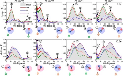
As already seen in the difference images in Figures – and the ISAs in Figure , the odd state shows a clear preference for collisions near the N atom of the molecule in both spin-orbit manifolds (
orientations, red/green traces) and across the entire range of scattering angles. For the even
state, collisions towards the O atom (
orientations, blue/purple traces) dominate in general, but N-side collisions (red trace) become important for the spin-orbit changing collisions, especially in the region of the second peak around
. This again reflects the overall preference for N-side/N-end interactions in spin-orbit changing collisions, where scattering is more efficient the closer the rare gas can approach the unpaired electron.
The maximised DCSs and the DCSs for the different orientations for spin-orbit changing collisions (columns 3 and 4) are strikingly similar for Ar and Kr, indicating very similar collision dynamics. In contrast, the DCSs for the spin-orbit conserving transitions exhibit different features and varying orientational preferences for the two rare gases (columns 1 and 2), particularly in the forward scattered direction. For the odd transition, the
orientation is close to the more forward scattered maximised DCS, while the
orientation more closely matches the maximised DCS for the even
transition, which extends to higher scattering angles. These trends are consistent with our previous findings for NO + Ar scattering into the spin-orbit conserving manifold [Citation31, Citation32]. In that case, side-on orientations were found to be generally favoured in the more forward scattered region (
), whereas end-on orientations dominated in the more backward scattered region (
). In addition, generally the differences between the DCSs for the
and the
orientations appear a bit less stark in the spin-orbit conserving data for Kr than for Ar.
Interestingly, a sharp forward scattered peak appears in the Kr DCSs for both spin-orbit manifolds, but only in the spin-orbit changing DCSs for NO + Ar. In our previous work on spin-orbit changing collisions of NO + Ar, we have attributed this prominent feature to trajectories on the A PES that are efficiently funnelled from the O-end through the attractive well on the side of the NO molecule and closely approach the extended width at the N-end, where the unpaired electron lies within the plane of the three atoms [Citation33].
Figure compares the infinite field DCSs for the and
final states, calculated separately on the A
, the A
, and the sum potentials, with the DCSs calculated for
and
on the full potentials. The data for NO + Ar are shown in the grey shaded panels; the data for NO + Kr are shown in the white panels. Generally speaking, the spin-orbit conserving DCSs calculated on the full potentials (column 4) for NO + Ar look a lot like the DCSs obtained on the A
PES only, which physically makes sense, since spin-orbit conserving collisions are more likely when the Ar approaches the NO molecule out of the plane of the unpaired electron. However, the respective DCSs for NO + Kr look more similar to the DCSs calculated on the sum potential. This suggests that for spin-orbit conserving transitions the NO + Kr interaction involves more of an equal mix of encounters on the adiabatic A
and A
PESs, whilst encounters on the A
PES dominate in the case of NO + Ar [Citation33]. In particular, the forward scattered feature observed in the A
DCSs for both collision systems (column 1) is carried over into both spin-orbit manifolds for NO + Kr, but only into the spin-orbit excited manifold for NO + Ar. In both systems, the spin-orbit changing DCSs (column 5) show contributions from the A
as well as the A
PESs and look very similar to one another.
Figure 9. Infinite field DCSs for the (top two panels) and
(bottom two panels) transitions calculated on the A
, A
, and sum PESs, as well as the full PESs for the spin-orbit conserving (
) and changing (
) manifolds (left to right). The grey shaded panels are for NO + Ar, and the white panels are for NO + Kr. The
and
orientations are represented in red and blue, respectively, and the
and
orientations in purple and green, respectively.
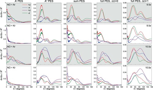
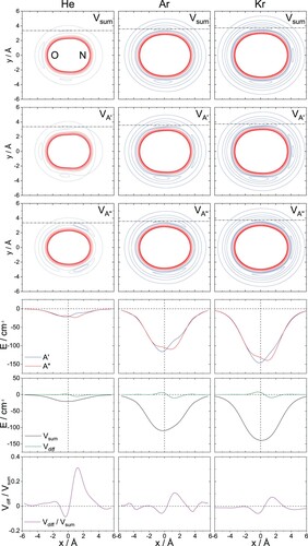
Figure 10. Sum, A, and A
potential energy surfaces (rows 1–3) for He, Ar, and Kr (left to right). Repulsive parts of the potential are represented in red with an energy spacing of 100 cm
, attractive parts are represented in blue with an energy spacing of 25 cm
. The additional dotted blue lines in the He potentials correspond to 10 cm
and 20 cm
. The fourth row shows cuts along the attractive well on the side of the A
(blue) and A
(red) potentials, as indicated by the dash-dotted line in the corresponding PESs. Rows 5 and 6 show the sum (black) and difference (green) potentials, and the
ratio (purple) along the same y-coordinate as in row 4.
The similarities of the NO + Ar and the NO + Kr systems in , and their dissimilarities in
, suggest that the differences observed in the spin-orbit branching fractions for the two systems (Figure ) are mainly due to differences in the spin-orbit conserving manifold. Owing to the higher polarisability of the heavier Kr atom, the NO + Kr potential extends further and features deeper attractive regions than the NO + Ar PES (Figure ). The repulsive cores of the two potentials, however, only slightly differ by how far they extend from the centre of mass, as illustrated in Figure S3 of the Supplemental Material. The repulsive parts of the potential play an important role for more impulsive, low-impact parameter collisions, which are required for high
transitions, as well as spin-orbit changing excitations. The attractive parts of the PES, on the other hand, determine the scattering outcome of high-impact parameter collisions that lead to predominantly forward scattered distributions, which dominate the spin-orbit conserving transitions. These forward scattered features are typically sharp and narrow and are sensitive to the specific topology and well depths in the attractive regions [Citation55].
Figure compares the sum, A′, and A′′ PESs (top three rows) for NO + Kr (right column) with the ones for NO + He (left column) and NO + Ar (middle column). While the potentials for NO + He are clearly dominated by the repulsive core (represented in red), the attractive regions (represented in blue) become more extended and deeper with increasing mass of the rare gas atom. The extended width near the N-end in the A PES is obvious in all three systems, indicating the location of the unpaired electron. The bottom three rows in Figure show cuts along the attractive well on the side of the A
(blue trace), the A
(red trace), the sum (black trace), and the difference (green trace) potentials, as well as the difference PES divided by the sum PES,
(purple trace). The position of the cuts are indicated by the dash-dotted lines in the corresponding A
, A
, and sum PESs.
For NO + He, the cuts through the sum and difference potentials reveal that although the sum potential is more attractive and the difference potential has small positive and negative regions, the scales of the two potentials are comparable. For NO + Ar and NO + Kr, the sum potentials are much more attractive than the He sum potential, and more so for NO + Kr. The difference potentials for the Ar and Kr systems along the attractive well are very similar. Since the difference potential has a stronger influence on the spin-orbit changing transitions, and the sum potential on the spin-orbit conserving transitions [Citation44], the population of spin-orbit changing states relative to the spin-orbit conserving ones are expected to be significant for NO + He and become smaller for NO + Ar and NO + Kr. Indeed, this is what we observe in the experimentally determined and calculated spin-orbit fractions for NO + Ar/Kr in Figure and for NO + He in Figure S1 of the Supplemental Material.
For NO + Ar and NO + Kr, the similar shapes and amplitudes of the difference PES cuts provide an explanation for the similar oriented DCSs found for spin-orbit changing collisions in these two systems (refer back to Figure ). For the spin-orbit conserving transitions, the deeper sum potential for NO + Kr leads to more forward scattered cross sections than for NO + Ar. The corresponding low intensities in the more backward direction of the spin-orbit conserving NO + Kr DCSs leads to an increase in the relative population of the spin-orbit changing transitions for odd transitions compared to the Ar system. At the same time, the variations in the branching fractions for the even
transitions become less pronounced for NO + Kr than for NO + Ar (see Figure ), as the attractive regions of the more extended NO + Kr PESs dampen the effect of the repulsive core. The scattering dynamics of the different NO + rare gas systems are thus determined by a delicate balance between the attractive and repulsive forces of the PESs.
4. Conclusions
We have measured the scattering distributions of side-on and end-on oriented NO molecules colliding with Kr atoms and compared them with full QM calculations. From the experimentally determined and calculated polarisation moments, we were are able to calculate differential cross sections at any arbitrary orientation. Similarly, the measured and calculated integral steric asymmetries for the x- and z-axis orientations allowed us to evaluate the spin-orbit branching fractions at any given orientation. We observe significant variations in the scattering distributions and integral branching fractions as a function of initial orientation of the collision partners, demonstrating once more how the collision outcome can be controlled by defining the collision geometry.
The differences between the collision dynamics for NO + Kr and NO + Ar highlight the importance of the attractive parts of the PES, particularly for low and intermediate transitions in the spin-orbit conserving manifold, which are characterised by high-impact parameter trajectories that lead to predominantly forward scattered DCSs. The more extended and deeper attractive regions of the NO + Kr potential result in more pronounced forward scattering for the intermediate
excitations and wash out some of the clearer orientational effects we have observed previously for NO + Ar. The roles of encounters on the A
and A
potentials to the scattering dynamics for the spin-orbit conserving transitions appear more equal for NO + Kr than for NO + Ar, which is largely dominated by out of plane encounters on the A
potential [Citation33]. The spin-orbit changing transitions, which are typically more sideways and backward scattered, are dominated by the repulsive parts of the potential, with collisions towards the N atom being overall more efficient, owing to the location of the unpaired electron. Because the repulsive core of the NO + Ar and NO + Kr potentials are very similar, both in shape and range, the spin-orbit changing DCSs for the two collision systems exhibit matching features, pointing to very similar collision dynamics.
Supplemental Material
Download PDF (836.2 KB)Disclosure statement
No potential conflict of interest was reported by the author(s).
Additional information
Funding
References
- M.H. Alexander, Chem. Phys. 92, 337–344 (1985). doi:https://doi.org/10.1016/0301-0104(85)85029-1.
- M.H. Alexander, J. Chem. Phys. 111, 7426–7434 (1999). doi:https://doi.org/10.1063/1.480066.
- J. Kłos, G. Chałasiński, M.T. Berry, R. Bukowski and S.M. Cybulski, J. Chem. Phys. 112, 2195–2203 (2000). doi:https://doi.org/10.1063/1.480785.
- P.R. Brooks and E.M. Jones, J. Chem. Phys. 45, 3449–3450 (1966). doi:https://doi.org/10.1063/1.1728128.
- R.J. Beuhler, R.B. Bernstein and K.H. Kramer, J. Am. Chem. Soc. 88, 5331–5332 (1966). doi:https://doi.org/10.1021/ja00974a059.
- M.H.M. Janssen, J.W.G. Mastenbroek and S. Stolte, J. Phys. Chem. A 101, 7605–7613 (1997). doi:https://doi.org/10.1021/jp971159+.
- M.C. van Beek, J.J. ter Meulen and M.H. Alexander, J. Chem. Phys. 113, 637–646 (2000). doi:https://doi.org/10.1063/1.481840.
- J.P. Wurm, I. Holdermann, J.H. Overbeck, P.H.O. Mayer and R. Sprangers, Proc. Natl. Acad. Sci. U.S.A. 114, 6034–6039 (2017). doi:https://doi.org/10.1073/pnas.1704496114.
- A. Meir, A. Abdelhai, Y. Moskovitz and S. Ruthstein, Biophys. J. 112, 2494–2502 (2017). doi:https://doi.org/10.1016/j.bpj.2017.05.013.
- M. van Son, J.T. Schilder, A. Di Savino, A. Blok, M. Ubbink and M. Huber, ChemPhysChem 21, 1060–1069 (2020). doi:https://doi.org/10.1002/cphc.v21.10.
- M. Karplus and M. Godfrey, J. Am. Chem. Soc. 88, 5332–5333 (1966). doi:https://doi.org/10.1021/ja00974a060.
- F.J. Aoiz, J.E. Verdasco, V.J. Herrero, V. Sáez Rábanos and M.A. Alexander, J. Chem. Phys. 119, 5860–5866 (2003). doi:https://doi.org/10.1063/1.1603223.
- J.F.E. Croft, N. Balakrishnan, M. Huang and H. Guo, Phys. Rev. Lett. 121, 113401 (2018). doi:https://doi.org/10.1103/PhysRevLett.121.113401.
- O. Ghafur, A. Rouzee, A. Gijsbertsen, W.K. Siu, S. Stolte and M.J.J. Vrakking, Nat. Phys. 5, 289–293 (2009). doi:https://doi.org/10.1038/nphys1225.
- F. Wang, J. Lin and K. Liu, Science 331, 900–903 (2011). doi:https://doi.org/10.1126/science.1199771.
- W.E. Perreault, N. Mukherjee and R.N. Zare, Science 358, 356–359 (2017). doi:https://doi.org/10.1126/science.aao3116.
- T.R. Sharples, J.G. Leng, T.F.M. Luxford, K.G. McKendrick, P.G. Jambrina, F.J. Aoiz, D.W. Chandler and M.L. Costen, Nat. Chem. 10, 1148–1153 (2018). doi:https://doi.org/10.1038/s41557-018-0121-9.
- A. Boca and B. Friedrich, J. Chem. Phys. 112, 3609–3619 (2000). doi:https://doi.org/10.1063/1.480514.
- S.D.S. Gordon, J.J. Omiste, J. Zou, S. Tanteri, P. Brumer and A. Osterwalder, Nat. Chem. 10, 1190–1195 (2018). doi:https://doi.org/10.1038/s41557-018-0152-2.
- B. Friedrich, D.R. Herschbach, J.-M. Rost, H.-G. Rubahn, M. Renger and M. Verbeek, J. Chem. Soc. Faraday Trans. 89, 1539–1549 (1993). doi:https://doi.org/10.1039/ft9938901539.
- J. van Leuken, J. Bulthuis, S. Stolte and J. Snijders, Chem. Phys. Lett. 260, 595–603 (1996). doi:https://doi.org/10.1016/0009-2614(96)00926-8.
- P.R. Brooks, E.M. Jones and K. Smith, J. Chem. Phys. 51, 3073–3081 (1969). doi:https://doi.org/10.1063/1.1672458.
- E.M. Jones and P.R. Brooks, J. Chem. Phys. 53, 55–58 (1970). doi:https://doi.org/10.1063/1.1673832.
- M. de Lange, M. Drabbels, P. Griffiths, J. Bulthuis, S. Stolte and J. Snijders, Chem. Phys. Lett. 313, 491–498 (1999). doi:https://doi.org/10.1016/S0009-2614(99)01065-9.
- A. Gijsbertsen, H. Linnartz, G. Rus, A.E. Wiskerke, S. Stolte, D.W. Chandler and J. Kłos, J. Chem. Phys. 123, 224305 (2005). doi:https://doi.org/10.1063/1.2126969.
- A. Gijsbertsen, H. Linnartz, C.A. Taatjes and S. Stolte, J. Am. Chem. Soc. 128, 8777–8789 (2006). doi:https://doi.org/10.1021/ja057828b.
- B. Nichols, H. Chadwick, S.D.S. Gordon, C.J. Eyles, B. Hornung, M. Brouard, M.H. Alexander, F.J. Aoiz, A. Gijsbertsen and S. Stolte, Chem. Sci. 6, 2202–2210 (2015). doi:https://doi.org/10.1039/C4SC03842H.
- M. Brouard, H. Chadwick, S.D.S. Gordon, B. Hornung, B. Nichols, F.J. Aoiz and S. Stolte, J. Chem. Phys. 144, 224301 (2016). doi:https://doi.org/10.1063/1.4952649.
- M. Brouard, S.D.S. Gordon, A. Hackett Boyle, C.G. Heid, B. Nichols, V. Walpole, F.J. Aoiz and S. Stolte, J. Chem. Phys. 146, 014302 (2017). doi:https://doi.org/10.1063/1.4972565.
- M. Brouard, S.D.S. Gordon, B. Nichols, V. Walpole, F.J. Aoiz and S. Stolte, Phys. Chem. Chem. Phys. 21, 14173–14185 (2019). doi:https://doi.org/10.1039/C8CP06225K.
- C.G. Heid, V. Walpole, M. Brouard, F.J. Aoiz and P.G. Jambrina, Nat. Chem. 11, 662–668 (2019). doi:https://doi.org/10.1038/s41557-019-0272-3.
- V. Walpole, C.G. Heid, P.G. Jambrina, F.J. Aoiz and M. Brouard, J. Phys. Chem. A 123, 8787–8806 (2019). doi:https://doi.org/10.1021/acs.jpca.9b07264.
- C.G. Heid, I.P. Bentham, V. Walpole, R. Gheorghe, P.G. Jambrina, F.J. Aoiz and M. Brouard, Phys. Chem. Chem. Phys. 22, 22289–22301 (2020). doi:https://doi.org/10.1039/D0CP04228E.
- M. Brouard and C. Vallance, editors, Tutorials in Molecular Reaction Dynamics (Royal Society of Chemistry, Cambridge, 2012).
- A.R. Hoy, J.W.C. Johns and A.R.W. McKellar, Can. J. Phys. 53, 2029–2039 (1975). doi:https://doi.org/10.1139/p75-254.
- R.N. Zare, Angular Momentum (Wiley-Interscience, New York, 1987).
- J. Brown, J. Hougen, K.-P. Huber, J. Johns, I. Kopp, H. Lefebvre-Brion, A. Merer, D. Ramsay, J. Rostas and R. Zare, J. Mol. Spectrosc. 55, 500–503 (1975). doi:https://doi.org/10.1016/0022-2852(75)90291-X.
- A. Gijsbertsen, W. Siu, M.F. Kling, P. Johnsson, P. Jansen, S. Stolte and M.J.J. Vrakking, Phys. Rev. Lett. 99, 213003 (2007). doi:https://doi.org/10.1103/PhysRevLett.99.213003.
- M.H. Alexander and S. Stolte, J. Chem. Phys. 112, 8017–8026 (2000). doi:https://doi.org/10.1063/1.481401.
- R. Uberna, R.D. Hinchliffe and J.I. Cline, J. Chem. Phys. 105, 9847–9858 (1996). doi:https://doi.org/10.1063/1.472935.
- A.J.B. Eppink and D.H. Parker, Rev. Sci. Instrum. 68, 3477–3484 (1997). doi:https://doi.org/10.1063/1.1148310.
- D.W. Chandler and P.L. Houston, J. Chem. Phys. 87, 1445–1447 (1987). doi:https://doi.org/10.1063/1.453276.
- M.H. Alexander, J. Chem. Phys. 76, 5974–5988 (1982). doi:https://doi.org/10.1063/1.442951.
- M.H. Alexander, J. Chem. Phys. 99, 7725–7738 (1993). doi:https://doi.org/10.1063/1.465702.
- F.J. Aoiz, M.T. Martínez and V. Sáez Rábanos, J. Chem. Phys. 114, 8880–8896 (2001). doi:https://doi.org/10.1063/1.1350916.
- C.G. Heid, I.P. Bentham, V. Walpole, P.G. Jambrina, F.J. Aoiz and M. Brouard, J. Phys. Chem. Lett. 12, 310–316 (2021). doi:https://doi.org/10.1021/acs.jpclett.0c02941.
- B. Wen, H. Meyer, J. Kłos and M.H. Alexander, J. Phys. Chem. A 113, 7366–7375 (2009). doi:https://doi.org/10.1021/jp811513j.
- HIBRIDON is a package of programs for the time-independent quantum treatment of inelastic collisions and photodissociation written by M.H. Alexander, D.E. Manolopoulos, H. Werner and B. Follmeg, with contributions by P.F. Vohralik, D. Lemoine, G. Corey, R. Gordon, B. Johnson, T. Orlikowski, A. Berning, A.D. Esposti, C. Rist, P. Dagdigian, B. Pouilly, G. van der Sanden, M. Yang, F. de Weerd, S. Gregurick and J. Kłos.
- D.E. Manolopoulos, J. Chem. Phys. 85, 6425–6429 (1986). doi:https://doi.org/10.1063/1.451472.
- M.H. Alexander, J. Chem. Phys. 111, 7435–7439 (1999). doi:https://doi.org/10.1063/1.480067.
- M. Yang and M.H. Alexander, J. Chem. Phys. 103, 6973–6983 (1995). doi:https://doi.org/10.1063/1.470323.
- V. Khare, D.J. Kouri and D.K. Hoffman, J. Chem. Phys. 74, 2275–2286 (1981). doi:https://doi.org/10.1063/1.441344.
- D.K. Hoffman, J.W. Evans and D.J. Kouri, J. Chem. Phys. 80, 144–148 (1984). doi:https://doi.org/10.1063/1.446498.
- H. Chadwick, B. Nichols, S.D.S. Gordon, B. Hornung, E. Squires, M. Brouard, J. Kłos, M.H. Alexander, F.J. Aoiz and S. Stolte, J. Phys. Chem. Lett. 5, 3296–3301 (2014). doi:https://doi.org/10.1021/jz501621c.
- J. Onvlee, S.N. Vogels, A. van der Avoird, G.C. Groenenboom and S.Y.T. van de Meerakker, New J. Phys. 17, 055019 (2015). doi:https://doi.org/10.1088/1367-2630/17/5/055019.
- R. Schinke, H.J. Korsch and D. Poppe, J. Chem. Phys. 77, 6005–6020 (1982). doi:https://doi.org/10.1063/1.443844.
- H.R. Mayne and M. Keil, J. Phys. Chem. 88, 883–891 (1984). doi:https://doi.org/10.1021/j150649a013.