
Abstract
For the Kilowatt Reactor Using Stirling TechnologY (KRUSTY) cold critical experiments, the KRUSTY component critical configuration was modified by the addition of parts that would be required for cold, warm, and hot critical experiments (including the vacuum chamber as well as the heat pipes and associated parts). Reactivity measurements were performed on the KRUSTY cold critical experimental configurations with the goal of obtaining reactivity-worth measurements on the beryllium oxide (BeO) reflector and the boron carbide (B4C) control rod parts. The resulting data are consistent and allow for accurate identification of the BeO and B4C part thicknesses required to achieve the excess reactivity needed for the KRUSTY warm and hot experimental configurations.
I. INTRODUCTION
The cold critical experiments for Kilowatt Reactor Using Stirling TechnologY (KRUSTY) occurred February to March 2018. The major difference between the cold critical experiments and the earlier component critical experimentsCitation1 is that the additional components required for the warm critical and hot critical experiments were installed for the cold critical experiments (vacuum chamber, heat pipes, etc.). These changes are detailed below. The purpose of the cold critical experiments was to measure the reactivity worth of the beryllium oxide (BeO) reflector as a function of height as well as the reactivity worth of the boron carbide (B4C) control rod as a function of height. The cold critical experiments were performed in preparation for the KRUSTY warm and hot experimental configurations in order to determine the heights of the BeO reflector and B4C control rod to achieve the required excess reactivities needed for those experimental configurations.
As detailed in CitationRef. 1, the KRUSTY experiment is a highly enriched uranium (HEU) core reflected by BeO, with a center annulus for the addition of a B4C control rod. A stainless steel shield surrounds the core to provide radiation shielding. The KRUSTY experiment is placed on the Comet Critical AssemblyCitation2–Citation4 at the National Criticality Experiments Research Center at the Device Assembly Facility at the Nevada Nuclear Security Site.
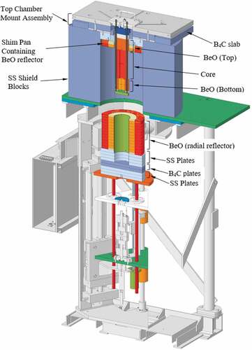
The Comet Critical Assembly is a vertical lift assembly (). The KRUSTY vacuum chamber containing the core and the stainless steel shields are placed upon the Comet top plate while the BeO radial reflector is placed upon the Comet moveable platen. In order to achieve a critical state, the platen and the BeO reflector are moved upward to surround the HEU core. Changes to the maximum reactivity of the system can be made by adjusting the height of the BeO reflector as well as adjusting the height of the B4C control rod. See for a detailed view of the KRUSTY experiment.
Fig. 1. Comet Critical Assembly.
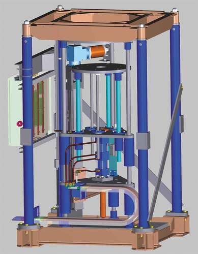
Fig. 2. Detailed view of the KRUSTY experiment with platen withdrawn. Note that the vacuum chamber, the Stirling engines, and the B4C control rod are not shown.
The KRUSTY experiment has been detailed in previous documents.Citation5–Citation7 A brief description of the important components for the cold critical KRUSTY measurements is detailed below. Changes to the system between the component critical and cold critical measurements are highlighted.
The KRUSTY fuel is composed of a 32-kg uranium alloy (7.65 wt% molybdenum) with a density of ~17.4 g/cm3 at room temperature. The uranium is isotopically enriched to 93 wt% 235U. The three uranium core components form the shape of an upright cylindrical annulus with an inner diameter (ID) of 4 cm, an outer diameter (OD) of 11 cm, and a height of 25 cm (, and ). The three core pieces have eight grooves equally spaced on the radial surfaces that extend axially to accommodate heat pipes. The heat pipes were in place during the cold critical experiments and will be detailed later.
Fig. 3. Bottom BeO reflector and uranium core components.
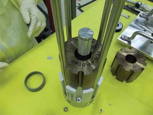
Fig. 4. Bottom BeO axial reflector and three core uranium components.
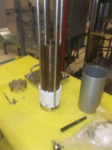
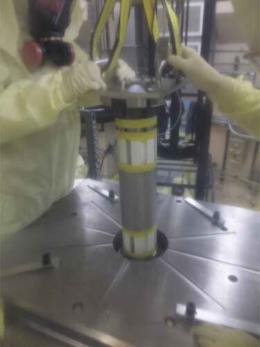
Fig. 5. Core and reflector components being lowered through the chamber mount assembly.
The inner annulus in the uranium core components is designed to accommodate the B4C control rod, which is enriched to 90% in 10B. The B4C control rod is composed of stacked discs of B4C (see ) with nominal dimensions of a 3.81-cm (1.5-in.) diameter and heights of 1.27 cm (0.5 in.) and 0.3175 cm (0.125 in.). Inserting the B4C control rod into the annulus in the uranium core decreases the reactivity of the system due to neutron absorption of the 10B. Variable-length B4C control rods were inserted into the core during the KRUSTY cold critical experiments in order to obtain the reactivity worth of the B4C control rod.
Fig. 6. B4C control rod detail.
, , and show the KRUSTY component critical hardware assembly used in the cold critical experiments. This hardware includes the fuel, the top and bottom BeO axial reflectors and plugs, the stainless steel and B4C shield pieces, and the AmBe source holder. The AmBe source was located in the source holder during operations and gave a source of neutrons in order to provide a meaningful measure of reactivity changes.
A 304 stainless steel bore shield top and a B4C bore shield sat on top of the top BeO axial reflector. The purpose of these items was to shield instrumentation and hardware on top of the core against gamma radiation. These shields were in place for all measurements.
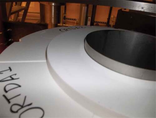
The BeO reflector was divided into three parts: the upper and lower axial reflectors and the radial reflector. The upper and lower axial BeO reflectors were part of the assembled core components described above. Each of the upper and lower axial BeO reflectors was 12.65 cm in diameter and 10.16 cm in height and had grooves to accommodate heat pipes. The radial reflector (, , and ) was made up of rings of different thicknesses to be able to limit the excess reactivity of the experiment. The inner side reflector rings had an inner diameter of approximately 14.5 cm and a 25.37-cm OD. The outer rings were divided into four parts. When assembled, the outer-side reflector rings had a 25.4-cm ID and a 38.1-cm OD.
Fig. 7. BeO radial reflector detail.
Fig. 8. BeO reflector (white) and bottom shield (silver and black) on Comet movable platen.
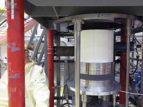
Fig. 9. Inner and outer BeO reflectors.
shows the KRUSTY experiment that was mounted on top of the Comet assembly. In moving from the component critical KRUSTY measurements to the cold critical KRUSTY measurements, the vacuum chamber and the eight heat pipes were installed around the KRUSTY core. The coolant in the heat pipes was sodium, which is solid at room temperature and liquid at 98°C. The volume of sodium in each heat pipe varied between 0.015 and 0.055 L. Each heat pipe had a length of 114 cm and an 1.27-cm OD. Six HAYN230 ring clamps equally spaced were installed around the core to tightly secure the heat pipes to the grooves in the periphery of the core (see ). The heat pipes operated such that one end of the heat pipe removed the heat from the core while the sodium in the heat pipe transferred the heat to the other end, where the heat from the sodium drove a Stirling engine or simulator. There was also a multilayer insulation wrapped around the heat pipes and core to reflect the heat escaping from the core back into the heat pipes. The Stirling engine and simulators sat on the top of the core and did not add any reactivity to the KRUSTY assembly. In addition, liquid nitrogen was pumped through an electric vaporizer assembly into the Stirling engines and simulators to cool them. Liquid nitrogen Dewar containers were located in a building adjacent to the building where KRUSTY was located.
Fig. 10. KRUSTY mounted on the Comet assembly.
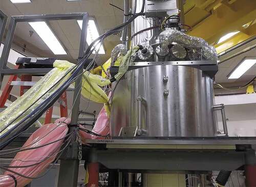
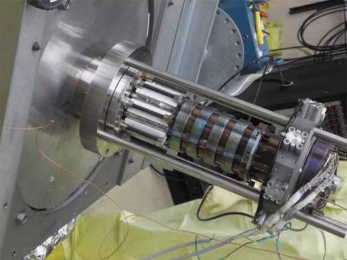
Fig. 11. Core components (brown-reddish) with top BeO reflector (white), heat pipes (light gray), HAYN230 ring clamps (light blueish).
Alignment of the vacuum chamber and the radial BeO reflector was performed by setting the vacuum chamber with fuel and heat pipes on top of the stainless steel shield. A tube called the centering ring was placed on the movable platen. Comet was operated locally to ensure that the centering ring (tube) was perfectly aligned around the vacuum chamber casing.
Finally, a test using electrical heat was conducted to ensure the operability of thermocouples, heat pipes, Stirling engines, and other data acquisition equipment. To conduct this test, an electric heater was installed in the center of the core and the fuel was heated up to 800°C.
Normally, the maximum reactivity limit for the Comet Critical Assembly is 0.80 $ of excess reactivity. For the hot critical experiment on KRUSTY, it was estimated that up to 3.00 $ of excess reactivity would be required to make up the loss of reactivity due to the increase in the fuel temperature of ΔT ~ 800°C. Measurements of the reactivity worths of the BeO and the B4C parts allowed for calculation of the exact heights of the BeO reflector and the B4C control rod in order to achieve 3.00 $ of excess reactivity for the hot critical experiment.
II. MATERIALS AND METHODS
One major purpose of the cold critical KRUSTY experiments was to determine the reactivity worth of the BeO reflector and the B4C control rod (similar to the earlier component critical KRUSTY experiments).
As BeO was added or removed from the reflector and B4C was added or removed from the control rod, reactivity measurements were taken of the resulting reactivity of the KRUSTY system. Typical increments in heights of the BeO reflector and the B4C control rod were in thicknesses of 0.3175 cm (0.125 in.). These changes and the results of the reactivity measurements are detailed below.
Two neutron detection data collection systems measure the neutron output from the Comet Critical Assembly. One system is named the Start-Up Counter System, which is composed of four 3He detectors embedded in polyethylene that operate in pulse mode. These Start-Up Counters can be moved around the Comet building and repositioned as needed. The second system is named the Linear Channel System, which is composed of three compensated ionization chambers that operate in current mode. These Linear Channel ionization chambers are mounted to the walls of the Comet building and cannot be repositioned.
Reactivity measurements for the KRUSTY experiment were performed by placing the KRUSTY experiment into a supercritical state (i.e., ρ > 0) such that the power or the neutron population in the system was exponentially increasing. This exponential rise in the neutron population would be measured and recorded by the Start-Up Counters or the Linear Channels. The resulting data are then analyzed using software that finds a fit to the exponential rise in the neutron population to determine the reactor period. Finally, the corresponding reactivity of the system is found by using the reactor period and the Inhour equation.
Note that for all the measurements described in this paper, the reactivity measurements reported were performed at the maximum reactivity for each configuration (i.e., the BeO reflector fully inserted around the core). The Inhour parameters used for the KRUSTY experiment found in originate from the Godiva Inhour parameters,Citation8 with a beta effective value of 0.0065. It is expected that the reactivity measurements for each configuration have measurement errors of approximately ±1 ¢.
TABLE I Inhour Parameters Used to CalculateReactivity from Reactor Period
III. RESULTS
lists the configurations that were performed for the cold critical experiment, the experimental modifications for each configuration, and the measured period and associated reactivity for the different configurations. No detailed simulations were performed for these configurations.
TABLE II Reactivity Measurements for KRUSTY Cold Critical Experiments
There were 52 configurations for the cold critical experiments. The average temperature of the fuel for all the configurations was 20.1°C. Configuration 1 in is considered to be the baseline configuration for the cold critical experiments. Configurations denoted with “No change” refer to additional measurements of the same configuration to determine measurement reproducibility. Note that the measurements started with configurations with 5.08 cm (2 in.) of BeO in the shim pan, but this thickness of BeO was eventually decreased to 2.54 cm (1 in.) of BeO in the shim pan (configuration 40 and later configurations).
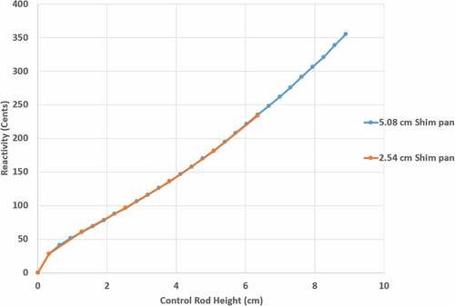
From the data in the worth of the B4C control rod can be found as a function of B4C height. A plot of these results can be found in . Data from configurations with both 5.08 cm (2 in.) and 2.54 cm (1 in.) of BeO in the shim pan are plotted together. Based on these data, it is important to state that a B4C control rod that is 12.7 cm (5 in.) in length and with the same diameter as the B4C discs used in this experiment would have enough negative reactivity to shut down this type of reactor that has 3.00 $ of excess reactivity.
IV. DISCUSSION
As can be seen in , the reactivity-worth data for both the 5.05-cm (2-in.) and 2.54-cm (1-in.) BeO shim pan configurations match very well. These data also compare well to the reactivity-worth data collected during the component-critical KRUSTY experiments.
These data on the B4C control rod worth were used to calculate the required BeO radial reflector height as well as the B4C control rod height for the increased excess reactivity required for the hot critical (high-temperature) measurement on KRUSTY, estimated at 3.00 $ of excess reactivity. To achieve the desired excess reactivity using the above data, the calculated BeO reflector height was 29.845 cm (11.75 in.) and the calculated B4C control rod height was 0 cm (0 in.).
Fig. 12. B4C control rod worth measurement data.
V. FUTURE WORK
In-depth and detailed computational models of the KRUSTY cold critical experiments are being developed for future inclusion in the International Criticality Safety Benchmark Evaluation Project Benchmark Handbook.Citation9 It is expected that the KRUSTY cold critical experiments and benchmark models will be used to validate and identify deficiencies in radiation transport codes and their associated computational methods and underlying nuclear data, in particular with regard to beryllium nuclear cross-section data.
Acknowledgments
This work was supported by the U.S. Department of Energy (DOE) Nuclear Criticality Safety Program funded and managed by the National Nuclear Security Administration for the DOE.
References
- R. G. SANCHEZ, “NCSP IER-299 CD-3B Documentation,” LA-CP-19-20000, Los Alamos National Laboratory (Jan. 2019).
- R. MOSTELLER, R. BREWER, and J. SAPIR, “The Initial Set of Zeus Experiments: Intermediate-Spectrum Critical Assemblies with a Graphite-HEU Core Surrounded by a Copper Reflector,” International Handbook of Evaluated Criticality Safety Benchmark Experiments, NEA/NSC/DOC/(95)03/II, HEU-MET-INTER-006, Nuclear Energy Agency (2019).
- D. HAYES, “Zeus: Fast-Spectrum Critical Assemblies with an Iron - HEU Core Surrounded by a Copper Reflector,” International Handbook of Evaluated Criticality Safety Benchmark Experiments, NEA/NSC/DOC/(95)03/II, HEU-MET-FAST-072, Nuclear Energy Agency 8(2019).
- R. MOSTELLER, “The Unmoderated Zeus Experiment: A Cylindrical HEU Core Surrounded by a Copper Reflector,” International Handbook of Evaluated Criticality Safety Benchmark Experiments, NEA/NSC/DOC/(95)03/II, HEU-MET-FAST-073, Nuclear Energy Agency (2019).
- D. I. POSTON, “KRUSTY Design and Modelling,” LA-UR-16-28377, Los Alamos National Laboratory (Nov. 2016).
- D. I. POSTON, “KRUSTY Test Results,” LA-UR-18-23685, Los Alamos National Laboratory (Apr. 2018).
- D. I. POSTON, et al., “Design of the KRUSTY Reactor,” presented at the Nuclear and Emerging Technologies for Space Conf., NETS 2018, Las Vegas, Nevada, p. 58, February 26–March 1, 2018.
- G. ROBERT KEEPIN, Physics of Nuclear Kinetics, Addison-Wesley Publishing Company, Inc., Reading, Massachusetts (1965).
- International Handbook of Evaluated Criticality Safety Benchmark Experiments, NEA 7497, Organisation for Economic Co-operation and Development/Nuclear Energy Agency (2019).