
Abstract
A series of critical experiments were conducted at the National Criticality Experiments Research Center (NCERC) in Nevada to evaluate the operational performance of a compact reactor that eventually will resemble the flight unit the National Aeronautics and Space Administration will use for deep space exploration. The results from the experiments are compared to preliminary results from computational models using MCNP and ENDF/B-7.1 neutron cross-section data.
I. INTRODUCTION
For more than 30 years, the National Aeronautics and Space Administration (NASA) has relied on radioisotope thermoelectric generators to produce the electricity that is used to power instrumentation in spacecraft or Rover vehicles deployed to other planets. In the 2000s, NASA decided to explore other sources of energy to produce electricity for spacecraft that will be used for a deep space exploration mission. In 2012, the National Criticality Experiments Research Center (NCERC) conducted a successful experiment that demonstrated how nuclear heating can be transferred with the use of a heat pipe into a Stirling engine and produce electricity.Citation1,Citation2
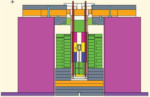
The main objective of the Kilowatt Reactor Using Stirling TechnologYCitation3–Citation5 (KRUSTY) experiment was to evaluate the operational performance of a compact reactor that closely resembles the flight unit NASA will use for deep space exploration missions. In addition, the purpose of the experiments was to provide high-quality critical and reactor physics benchmarks that can be used to test neutron cross-section data used in steady-state and dynamic computer models. The component-critical experiment consisted of the core described below surrounded by a beryllium oxide (BeO) reflector and shield materials. As seen in , the radial BeO reflector and some of the shield materials [stainless steel and boron carbide (B4C) plates] sit on the movable platen of the Comet vertical assembly machine. The stainless steel shield blocks sit on the top platform of Comet. There are axial BeO reflectors. One of them sits on the top of the core and the other one is below the core (see ). There may be up to 2-in.-thick BeO plates in the shim pan located above the BeO radial reflector. Finally, the top chamber mount assembly and B4C slabs sit on top of the stainless steel blocks. The assembly of the core and other hardware is described below.
Fig. 1. Cross-section view of component-critical experiments (phase 1) (SS = stainless steel).
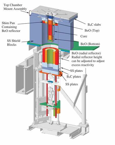
To attain a supercritical state, the radial reflector and shield materials on the movable platen were raised to partially surround the core. To increase the reactivity in the experiment, more BeO plates were added to the radial BeO on the movable platen, thus increasing the radial reflector height. The platen was raised and because more neutrons were reflected back into the core, the reactivity of the experiment increased.
The KRUSTY project was divided into four phases. The objective of phase 1 (component critical) and phase 2 (cold critical) was to assess the bias of the keff due to the BeO neutron cross-section data and to determine the reactivity worth of the B4C control rod that may be used in the flight unit that NASA may deploy to other planets. Phase 3 was the warm-critical runs that provided key parameters used in the modeling of the neutronic and thermal-dynamic behavior of the KRUSTY experiment. The data obtained in the previous phases were used in the high-temperature 28-h run (phase 4). As stated above, the experiments in phase 1 consisted of the fuel reflected with BeO and the stainless steel shield. The experiments in phases 2, 3, and 4 consisted of the fuel embedded in a vacuum chamber with eight heat pipes attached to the periphery of the fuel. Similar to phase 1, the fuel in the vacuum chamber was reflected by BeO and the stainless steel shield. This paper describes the experiment and the results obtained during the execution of phase 1 (component-critical) experiments. A comparison between experimental and preliminary computational results is presented.
II. DESCRIPTION OF THE COMPONENT-CRITICAL EXPERIMENT
The component-critical experiment was composed of a 32-kg uranium alloy (~7.65 wt% Mo) core with a calculated density of ~17.35 ± 0.02 g/cm3 at room temperature. The uranium was isotopically enriched to 93 wt%. The uranium core components (three of them) form the shape of an upright cylindrical annulus with an inner diameter of 4 cm and an outer diameter of 11 cm. shows the weights and isotopic composition of each of the three core components. The uranium core had a height of 25 cm. The three core pieces had eight grooves equally spaced on the radial surfaces that extended axially to accommodate heat pipes. The core was cast and machined at the U.S. Department of Energy’s (DOE’s) Y-12 National Security Complex. The heat pipes were not used as part of the component-critical experiments. The inner hole in the uranium core was designed to accommodate a B4C control rod. Segments of the B4C control rod were inserted in the uranium core during the phase 1 critical experiments to obtain the reactivity worth of the control rod.
TABLE I Weights and Isotopic Composition of theThree Components that Form the Core
through show the KRUSTY component-critical hardware used during the execution of (phase 1) component-critical experiments. As seen in through , the bottom axial BeO reflector containing the two BeO plugs was slid through the stainless steel rods and placed on top of the retaining plate, followed by the fuel. An AmBe neutron source was placed in the center of the fuel to induce fission neutrons and to better measure the true multiplication of the configurations. The neutron source was not always present for some of the configurations. The top axial BeO reflector was slid through the rod and placed on top of the fuel followed by one stainless steel and one B4C shield piece. The bottom and top axial BeO reflectors and the shield pieces had eight grooves equally spaced on their radial surfaces to accommodate heat pipes, similar to the fuel components. An aluminum sleeve or jacket was placed over the fuel. The rods seen in with reflectors, fuel, and shield pieces were attached to a squared hanger plate. The assembled core with axial reflectors and shield pieces was lowered through the chamber mount assembly plate and firmly secured (see ). Stainless steel shield blocks were also mounted on the top platform of the Comet assembly (see ). It should be noted that the reactivity of the experiment was controlled by raising or withdrawing the BeO radial reflector, which was mounted on the movable platen (see ).
Fig. 2. Bottom BeO reflector and one uranium core component. Neutron source is in the aluminum capsule.
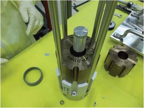
Fig. 3. BeO bottom reflector and two uranium core components.
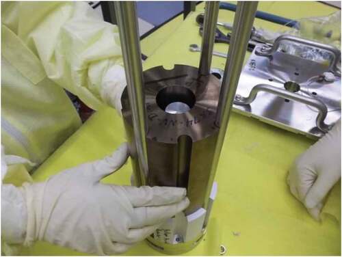
Fig. 4. Bottom axial reflector of BeO and three core uranium components.
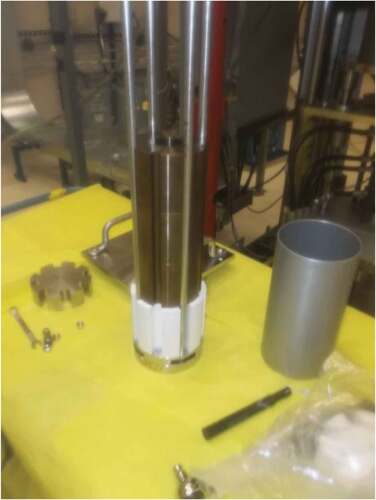
Fig. 5. Core and reflector components being lowered through the chamber mount assembly.
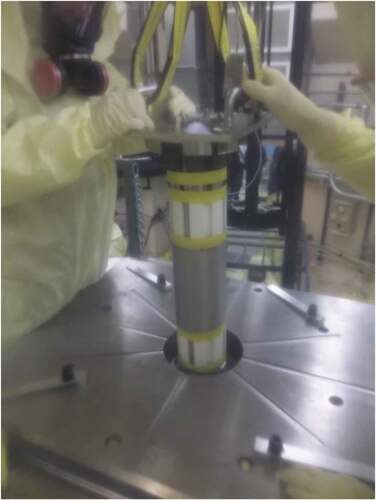
Fig. 6. Stainless steel shields and chamber mount assembly plate on top of the Comet assembly.
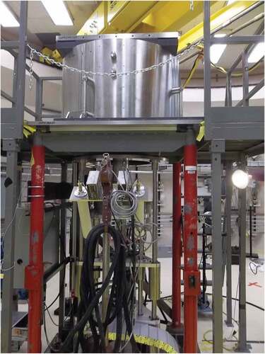
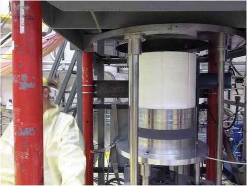
Fig. 7. BeO (white) radial reflector mounted on the movable platen of the Comet vertical assembly machine. Also, bottom 304 stainless steel shield (silver) with a layer of B4C (dark).
The 304 stainless steel bore shield top that sat on top of the top BeO axial reflector had an outer diameter of 12.7 cm and a height of 3.8 cm. The purpose of this piece was to shield instrumentation and hardware on top of the core against gamma radiation.
The B4C bore shield top sat on top of the 304 stainless steel bore shield top. Its purpose was to shield instrumentation and hardware on the top of the core against neutron radiation. This piece had an outer diameter of 14.6 cm, a step diameter of 12.7 cm, and was 1.9 cm deep. The overall height was 5.1 cm.
The square hanger plate was made of 304 stainless steel. It was a 1.3-cm-thick, 25.4-cm-square plate with a 20.9-cm-diameter central protrusion that was 3.5 cm thick.
The BeO reflector was divided into three parts: the upper and lower axial reflectors and the radial reflector. The upper and lower axial BeO reflectors were part of the assembled core components described above. Each of the upper and lower axial BeO reflectors was 12.7 cm in diameter and 10.2 cm in height and had grooves to accommodate heat pipes. The radial reflector was made up of rings of different thicknesses to be able to limit the excess reactivity of the experiment. The inner side reflector rings had an inner diameter of approximately 14.5 cm and an outer diameter of 25.4 cm. The outer rings were divided into four parts. When assembled, the outer side reflector rings had an inner diameter of 25.4 cm and an outer diameter of 38.1 cm. Hazards associated with handling the BeO reflector parts were analyzed and appropriate controls were in place to minimize personnel exposure. The average calculated density of the BeO parts was 2.82 ± 0.016 g/cm3.
The 304 stainless steel shield (shown in and ) was also divided into three parts: the radial shield, the lower shield, and the top chamber mount assembly.
The radial shield was divided into four parts. When assembled, the radial shield had an inner diameter of 40.6 cm and an outer diameter of 101.6 cm. The radial shield was approximately 66 cm in height.
The lower 304 stainless steel shield sat on the movable platen and had a layer of B4C to absorb neutrons that leak from the core. The bottom 304 stainless steel shield and the B4C had a diameter of 39.7 cm. The bottom part of the 304 stainless steel shield that sat on the movable platen had three plates with a total height of approximately 7.5 cm. The B4C layer sat on the top of the bottom 304 stainless steel shield and was composed of two plates with a total height of 5.1 cm. Another four 304 stainless steel shield plates sat on top of the B4C layer with an approximate inner diameter of 14 cm, an outer diameter of 39.7 cm, and a total height of 10.2 cm. The top chamber mount assembly was composed of a 304 stainless steel leveling plate, a B4C leveling plate, a 304 stainless steel lower leveling plate, B4C side bars, a 304 stainless steel outer top ring shield, and a 304 stainless steel inner top ring shield (shown in ). The 304 stainless steel upper leveling plate was 76.2 cm wide × 4.0 cm long × 3.81 cm thick with a 21.0-cm-diameter central hole. The B4C leveling plate was 63.5 cm wide × 76.2 cm long × 5.1 cm thick with a 21.0-cm-diameter central hole. The 304 stainless steel lower leveling plate was 63.5 cm wide × 76.2 cm long × 1.3 cm thick with a 21.0-cm central hole.
Fig. 8. Top chamber mount assembly (SS = stainless steel).
There were two B4C side bars. Each B4C side bar was 76.2 cm long × 15.2 cm wide × 5.1 cm thick. The 304 stainless steel outer top ring shield had an outer diameter of 41.0 cm, an inner diameter of approximately 21.6 cm, and a thickness of 6.4 cm. Finally, the 304 stainless steel inner top ring shield had an inner diameter of 14.0 cm, an outer diameter of 21.6 cm, and a thickness of 4.5 cm. As seen in , this piece had a flange at one end that extended to a 30.5-cm outer diameter and was 1.0 cm thick with an inner diameter of 14.0 cm. The average calculated density of the 304 stainless steel parts was 7.95 ± 0.2 g/cm3.
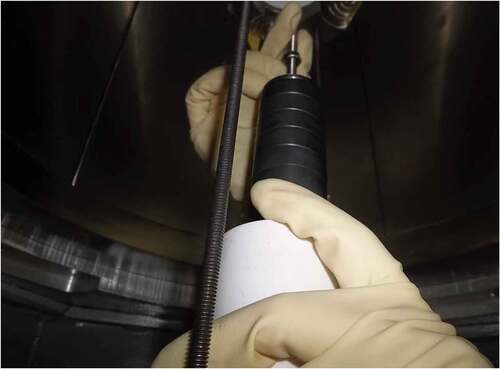
All B4C parts except the discs used as part of the control rod were made using natural boron. The average calculated density of the B4C parts with natural boron was 1.86 ± 0.01 g/cm3. The segments used as part of the control rod were made of enriched boron containing up to 90 wt% 10B. The B4C discs used as part of the control rod had an inner diameter of 0.635 cm and an outer diameter of 3.81 cm. Some of the discs were 1.27 cm thick while others were approximately 0.32 cm thick (see ). The average density for the enriched B4C discs was 2.12 ± 0.05 g/cm3.
Fig. 9. B4C (black discs) control rod being inserted into the center of the core. Also shown in the picture are the BeO plugs (white cylinders).
A detailed description of the parts mentioned above with their manufacturing tolerances, weights, material uncertainties, etc., is given in a document entitled “KRUSTY: Beryllium-Oxide and Stainless-Steel Reflected Cylinder of HEU Metal,” HEU-MET-FAST-101, which was submitted to the International Criticality Safety Benchmark Evaluation Project (ICSBEP) in October 2019 for review.Citation6
A resistance temperature detector was installed midpoint on the outer surface of the fuel to measure the temperature of the core and to ensure that the measured temperature is within the limits specified in the experiment plan.
The component-critical experiments were performed on the Comet vertical assembly machine. This machine consists of a drive assembly and a stationary support structure (see ). The BeO radial reflectors were mounted on the drive assembly and raised by a hydraulic lift and a ball screw linear motion driven by a stepper motor. Four 3He neutron startup detectors were positioned approximately 3 to 4 m from the assembly to monitor the neutron leakage from the assembly. A 1/M as a function of radial reflector height was performed to estimate the reflector height at which the configuration will go critical.
III. RESULTS
shows the configurations that were performed as part of the component-critical experiments (phase 1). A brief description of each configuration is given in the first column of , followed by the BeO radial reflector height, the height of BeO in the shim pan (see ), the B4C control rod height, the measured keff, the calculated keff, the difference between calculated and measured (experiment) keff’s, and the temperature of the configuration. There were 60 configurations that were performed during the phase 1 component-critical experiments. The average temperature for all the configurations was 16.3ºC. These experiments were performed between November 2017 and January 2018.
TABLE II Measured and Calculated keff for KRUSTY Component-Critical Experiments
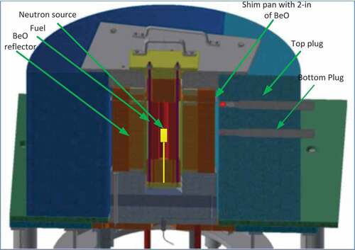
The neutron transport computer code MCNP6.2® (CitationRef. 7)Footnotea was used to calculate the keff for each configuration. A total of 25 million neutron histories were run for each configuration. The MCNP simulations used ENDF/B-VII neutron cross-section data. Neutron cross sections and the S(α, β) thermal scattering kernel for BeO were at 26.85ºC (300 K). The baseline MCNP modelCitation8 is shown in . This detailed model was created using measured data that were provided by the manufacturer for each piece including the impurities.Citation6 The MCNP model assumed that the core was perfectly centered with respect to the radial BeO reflector and there were no axial gaps in the radial reflector. The uncertainty in keff associated with the alignment of the central core column, alignment of the platen, and axial gaps between the radial BeO reflector rings is given in CitationRef. 6. It is important to note that the calculated keff’s shown in are preliminary and they may change as the detailed model continues to evolve.
Fig. 10. MCNP model of KRUSTY.
For all the configurations in that showed a measured keff greater than 1, an exponential rise in the neutron population was observed. The data are fitted and a reactor period is determined. The reactor period is then input into the Inhour equation,Citation9 and from this equation the reactivity of the configuration is found. To convert reactivity into keff, a βeff of 0.00711 ± 0.0002 was used. The βeff was calculated using the KOPTS (CitationRef. 6) card in MCNP.
Configurations 1 and 10 are considered baseline cases and in both cases MCNP calculates about 365 pcm below the measured keff. Configuration 2 compares how reproducible the measured keff is of the configuration assembled in configuration 1 by unstacking part of the radial reflector and then putting it back again. As seen in , there is a small difference in the measured keff between configurations 1 and 2 mainly due to the alignment of the last 1/4-in.-thick BeO radial reflector plate. This alignment issue was partially corrected in configuration 7 and completely corrected in configuration 10. The difference in the measured keff’s between configurations 1, 7, and 10 is quite small.
Configurations 4, 5, and 6 investigated the effects in the reactivity, and for that matter in the keff of removing the top, the bottom, or both stainless steel shield plugs shown in . Measured and calculated keff values showed no significant effect.
Fig. 11. Component-critical experiment (phase 1).
Configuration 11 investigated the reactivity effect of removing the AmBe neutron source and the aluminum source holder. As seen in , removing the AmBe neutron source and the source holder removed about 51 pcm when compared to configuration 1. The MCNP simulations also confirmed the loss of reactivity due to the removal of source and source holder.
Configurations 8, 10, 13, 16, 23, 29, 32, and 33 determined the reactivity worth per mil of adding the BeO radial reflector to the assembly. The reactivity per mil varied from 2.32 to 2.64 pcm/mil. This measurement was very important because it allows us to estimate the BeO reflector thickness that was needed to have enough excess reactivity to heat the fuel up to 800°C for the high-temperature 28-h run (phase 4).
Configurations 3, 9, 12, 15, 17, 20, 24, 27, 34, 39, 50, and 55 are the “no change” configurations, meaning that they are the same as the previous configurations. For example, configuration 15 was the same as configuration 14; configuration 3 was the same as configuration 2, and so on. The main objective of these measurements was to demonstrate the reproducibility of the reactivity measurements.
Configurations 14, 18, 19, and 21 investigated the reactivity addition or subtraction due to adding or retrieving the aluminum source holder and source holder rods to/from the center of the core or placing the neutron source in the top or bottom source plug location (see ). As seen in , the changes described above added or subtracted between 1 and 14 pcm of reactivity.
Configuration 22 investigated the reproducibility in reactivity of opening and closing the stainless steel shield door. As illustrated in , this action represents a difference of 5 pcm between the reactivity in this configuration and that of configuration 21.
Configurations 25, 26, and 28 investigated the reactivity effects of replacing the top and/or bottom BeO reflector plugs with aluminum plugs. Measured and calculated keff’s showed the same trend, although for configurations 25 and 26 the calculated keff’s are about 375 pcm on average below the measured keff’s. Note that in configuration 28, replacing both BeO plugs with aluminum plugs (see ), was subcritical.
In configurations 30 and 31 a new diagnostic bottom replaced the old diagnostic bottom. A stainless steel threaded rod was added to the new diagnostic bottom. This change made a very small difference in reactivity (configurations 30 and 31 compared to 14).
Configuration 44 explored the reactivity effects of reshuffling the three core pieces. As seen in , a small reactivity difference was found between this configuration and configuration 1 (baseline).
Configuration 45 investigated the reactivity effect of adding an empty shim pan to the experiment (see ). Adding the empty shim pan had a positive reactivity effect (~60 pcm) compared to the baseline case (configuration 1). The simulations predicted an increase of reactivity of 51 pcm.
Configuration 46 investigated the reactivity effect of adding a 2-in.-thick BeO reflector to the shim pan. As seen in , the shim pan was located near the top part of the core. The addition of BeO to the shim pan added a considerable amount of reactivity, such that the radial reflector height had to be reduced from 11.25 to 10.375 in. (see ) in order to be within the 80-¢ (569 pcm) technical safety requirement limit. According to , the measured reactivity was approximately 331 pcm compared to 100 pcm from simulations.
In configuration 47, a 1/8-in.-thick BeO radial reflector was removed from configuration 46 and the reactivity was measured to be 0.1 ¢ (0.711 pcm). The simulation predicted 264 pcm below the measured reactivity.
Configuration 48 investigated the reactivity effect of adding four small 3He detectors to the periphery of the core. The addition of the 3He detectors reduced reactivity by approximately 6 ¢ (43 pcm) compared to configuration 46.
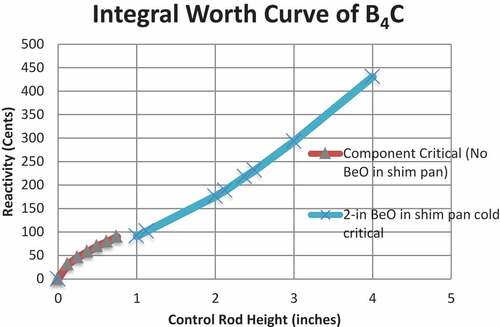
Configurations 35 through 43 and 49 through 60 investigated the reactivity effects of adding segments of B4C in the center of the core with no BeO in the shim pan and with 2-in.-thick BeO in the shim pan (see ). Based on these measurements, the integral worth curve as a function of control rod height is shown in . It is important to note that the central control rod proposed by NASA will have enough negative reactivity worth to shut down a reactor that would have 3.00 $ (2133 pcm) of excess reactivity.
Fig. 12. Integral worth curve of B4C control rod.
Finally, it should be noted that as the temperature of the room where the experiments were conducted increased, the difference between the calculated and measured keff’s got smaller (see ). A possible explanation is that the neutron cross sections and the thermal S(α, β) used in the MCNP models were evaluated at 300 K, while the majority of the experiments were executed in a room at a temperature of 15°C (288 K).
IV. CONCLUSIONS
A total of 60 configurations were performed as part of component-critical (phase 1) experiments. For the baseline configuration, the calculated keff was 366 pcm below the measured keff. An integral worth curve as a function of control rod height was attained. These data will be extremely useful because the proposed control rod that NASA will use in the flight unit is very similar to the one used in these experiments. Finally, it appears that as the temperature of the room where the critical experiments were being conducted increased, the difference in calculated and experimental keff’s decreased substantially.
V. FUTURE WORK
The intent of this paper was to document the experiments that were conducted as part of phase 1 and to compare them with preliminary simulations. A report entitled “KRUSTY: Beryllium-Oxide and Stainless-Steel Reflected Cylinder of HEU Metal,” HEU-MET-FAST-101, which has been summited to the ICSBEP for review, documents in great detail all the components used in these experiments. This report also discusses the uncertainties in keff associated with the uncertainties of the masses and manufacturing and machining tolerances of all the parts used in the experiments. A paper summarizing these results will be submitted to the Nuclear Technology journal in the near future.
Acknowledgments
This work is supported by the NASA Space Technology Program and in part by the DOE Nuclear Criticality Safety Program, funded and managed by the National Nuclear Security Administration for the DOE.
Notes
a MCNP® and Monte Carlo N-Particle® are registered trademarks owned by Triad National Security, LLC, manager and operator of Los Alamos National Laboratory. Any third party use of such registered marks should be properly attributed to Triad National Security, LLC, including the use of the designation as appropriate. For the purposes of visual clarity, the registered trademark symbol is assumed for all references to MCNP within the remainder of this paper.
References
- R. G. SANCHEZ, et al., “MCNP Simulations in Support of the Heat Pipe in Flattop Experiment,” LA-UR-13-20495, Los Alamos National Laboratory (Oct. 2013).
- D. I. POSTON, “Criticality and Dynamic Benchmarking of the DUFF Reactor Test,” LA-UR-13-20724, Los Alamos National Laboratory (Oct. 2013).
- D. I. POSTON, “KRUSTY Design and Modelling,” LA-UR-16-28377, Los Alamos National Laboratory (Nov. 2016).
- D. I. POSTON, “KRUSTY Test Results,” LA-UR-18-23685, Los Alamos National Laboratory (Apr. 2018).
- D. I. POSTON et al., “Design of the KRUSTY Reactor,” Proc. Topl. Mtg. Nuclear and Emerging Technologies for Space, pp. 58–61, American Nuclear Society (2018).
- K. N. SMITH, et al., “KRUSTY: Beryllium-Oxide and Stainless-Steel Reflected Cylinder of HEU Metal,” HEU-MET-FAST-101, Nuclear Energy Agency/OECD (Organization for Economic Co-operation and Development) (October 2019).
- D. B. PELOWITZ, et al., “MCNP6 User’s Manual,” LA-CP-14-00745, Los Alamos National Laboratory (June 2014).
- K. N. SMITH et al., “Preliminary Benchmark Analysis of Component Critical Configuration of KRUSTY,” Trans. Am. Nucl. Soc., 119, 819 (2018).
- G. R. KEEPIN, Physics of Nuclear Kinetics, Addison-Wesley Publishing Company, Inc., Reading, Massachusetts (1965).