
Abstract
The Kilowatt Reactor Using Stirling TechnologY (KRUSTY) was a reactor design, development, and test program to demonstrate the nuclear operation of a Kilopower reactor. Kilopower systems are intended to provide between 1 and 10 kW(electric) in space, or on the surface of planets or moons, with a clear evolution to substantially higher power systems. KRUSTY was a prototype of a 1-kW(electric) highly enriched uranium–fueled Kilopower system. In March of 2018, KRUSTY successfully operated as a fission power system and was the first nuclear-powered operation of any truly new reactor concept in the United States in over 40 years. This paper discusses the design of the KRUSTY reactor along with the philosophy, goals, and engineering work that ultimately led to KRUSTY’s success.
I. INTRODUCTION
Space fission power development in the United States has been a failure since the Systems for Nuclear Auxiliary Power (SNAP) program in the 1960s, with billions of dollars spent and no tangible results. The key contributing factor to these failures was that programs tried to take too difficult of a first step; i.e., the path to success was not sufficiently simple. Simplicity is essential to any first-of-a-kind engineering project, which does not necessarily mean finding the simplest design but rather finding the simplest path through design, development, fabrication, safety, and testing.
The Demonstration Using Flattop FissionsCitation1 (DUFF) experiment was envisioned as a simple step to prove that a positive step, no matter how small, could be taken to move space fission power forward. DUFF used an existing reactor, a simple heat pipe, a rudimentary heat exchanger, and existing Stirling converters to produce electricity. The DUFF experiment was completed for <$1 million in <6 months after it was first envisioned.
The Kilowatt Reactor Using Stirling TechnologY (KRUSTY) was envisioned as the next step toward successful deployment of a space reactor. KRUSTY was a prototypic nuclear-powered test of a 5-kW(thermal) Kilopower space reactor.Citation2 Kilopower reactor concepts utilize heat pipes to transfer fission energy from a solid block of fuel and are intended for simple, low-power [1- to 10 -kW(electric)] space and surface power systems. KRUSTY was designed to be as prototypic as possible within the cost constraints of a 3-year, <$20 million program.
This paper is one of eight papers in this Nuclear Technology special issue that documents the KRUSTY project through final testing in March 2018. This paper focuses on the reactor design, including the goals and approach that facilitated project success. Accompanying papers in this special issue provide additional detail about the power conversion systemCitation3 (PCS); regulatory approvalsCitation4; and test results from the cold criticals,Citation5,Citation6 warm criticals,Citation7 and full nuclear system test.Citation8
II. KILOPOWER REACTORS
shows the basic layout of a Kilopower system. Note that there is an intentional distinction in this paper between “reactor” and “system.” “Reactor” comprises the core, heat pipes, reflector, absorber rod, and shield. “System” comprises the power conversion system (PCS), which includes the converters, heat rejection, control, and overarching structure.
Fig. 1. Layout for 1-kW(electric) Kilopower system.
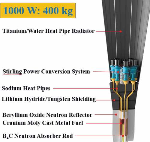
The Kilopower reactor concept is one of the simplest space power reactor concepts ever proposed. Perhaps the most important simplicity of the system is in neutron kinetics and system dynamics. The kinetics of a compact, fast reactor are dominated by one factor: changes in material density/geometry (changes in neutron interaction rates, i.e., cross sections, have small effects). The Kilopower solid core eliminates potential movements of fuel rods/pieces relative to others, and the surrounding geometry is fixed (except for small potential relative movements due to thermal expansion); thus, the only major reactivity effects are changes in neutron leakage/reallocation due to material expansion. This makes the start-up and operational system dynamics easy to predict/verify.
The basic Kilopower reactor components are fuel, heat pipes, control, reflector, and shield. Each component and how components integrate together are simplified by low power; e.g., at low powers [<100 kW(thermal)], thermal management and irradiation damage of components do not complicate system design. The simplicity of the system also leads to high reliability. The reactor is essentially solid state, with the control rod being the only moving part. Actually, at low powers [~10 kW(thermal)], the burnup reactivity is so small that long lifetime (10-plus years) could be achieved without any control movement after start-up; higher-power systems would require occasional (monthly or annual) control movement to maintain reactor temperature. At all power levels, Kilopower systems can survive worst-case transients (e.g., loss of heat removal by PCS) without any control action. The lack of need for real-time reactor control greatly simplifies system control. The Stirling controller can independently control the system, without potential interference and interactions caused by a separate control feature associated with the reactor. The reactor control system needs to move the control rod only at start-up, and whenever a boost in reactor temperature is desired, this could possibly be done remotely when deemed necessary by a ground engineer and thus not require any automated control software.
Another system attribute that leads to high reliability is inherent redundancy in heat transport. Each heat pipe is an independent, highly reliable mechanism. In all proposed Kilopower systems, full power can be delivered even with several heat pipes or Stirling engines failed. If three heat pipes that are directly adjacent to each other fail, then the power level may need to be reduced to avoid exceeding the fuel temperature limit (assuming that heat pipe failures can be diagnosed). The baseline Kilopower power conversion approach is to attach a single Stirling engine to a single heat pipe, which is referred to as the 1-for-1 approach. This was the configuration used in KRUSTY, which provides the simplest suite of technologies, the simplest system dynamics, and the highest efficiency (i.e., smallest temperature drop). The 1-for-1 configuration requires a large number of small engines, which may or may not be optimal from a cost and development perspective. One negative of this approach is that if a Stirling engine fails, it effectively fails a heat pipe in the core, whereas an intermediate heat transfer mechanism would eliminate this problem. However, the 1-for-1 approach provides a reliable diagnostic of heat pipe failure, which will allow mitigation of worst-case failure patterns if they indeed occur (noting that the probability of heat pipe failure will likely be much lower than that of a Stirling converter).
Kilopower reactors should also be very reliable with respect to launch and landing loads. A solid block of fuel eliminates potential fuel pin, grid plate movements. Heat pipes should also be less fragile than the alternative, which is coolant piping to and from the reactor, including connections to other loop components. Plus, the piping and connections will likely provide a single-point failure. The Kilopower Project has started to evaluate launch loads, and the system appears robust.
Finally, the compact reactor size allows for a simple approach to launch safety, transport, and nuclear and nonnuclear system testing. Kilopower reactors are essentially nonradioactive prior to operation. The only condition that can create a significant nuclear hazard is an inadvertent movement of the control rod that causes criticality. There is no conceivable launch or transport accident (including water, wet sand, etc.) that can cause criticality unless the rod is removed. More so, the system will go critical only if the rod is removed and the radial neutron reflector is geometrically intact. It is unlikely that any impact strong enough to remove the rod will not also remove, or at least significantly crack/deform, the radial reflector, and the system design can help ensure this. Therefore, the only significant nuclear safety engineering required for Kilopower is to ensure the rod does not move unless it is properly commanded to do so (which is a feature that any reactor must have by definition).
III. KEY DESIGN DECISIONS TO ALLOW REALISTIC COST AND SCHEDULE
KRUSTY was designed to demonstrate a concept as close to flight prototypic as possible while remaining affordable and allowing quick completion. As with DUFF, the key to success was making important early design choices that simplified all aspects of development and testing. KRUSTY would not be considered a realistic, affordable opportunity until the following issues were satisfied:
Use a fuel form that can be procured quickly and affordably. The only viable path was a UMo fuel form that could be cast in a similar manner to existing operations at the Y-12 Security Complex (Y-12) in Oak Ridge, Tennessee (size, shape, procedure).
Use an existing operational facility with experienced operations, safety, and compliance teams. The only viable option was to use the National Criticality Experiments Research Center (NCERC) within the Device Assembly Facility (DAF) at the Nevada National Security Site (NNSS).
Use an existing critical assembly machine for active reactivity insertion and removal. The NCERC machine COMET was found to have adequate mass and linear translation capabilities, which eliminated the cost and schedule risk of trying to qualify a new, safety-significant reactivity control system.
Provide adequate safety and asset risk (machine, room, facility). A power level of ~5 kW(thermal) was chosen to be in line with prior Flattop and DUFF operations while also being high enough for the useful flight system.
Use core dimensions that readily allow shipping in the existing/approved container. This limited the core diameter to 11 cm.
Reduce the cost and schedule impact of the PCS. Use two off-the-shelf converters and six thermal simulators to match the power removal of those specific converters.
IV. PRIORITIZATION OF KRUSTY GOALS
Given the key design decisions listed above, the focus then shifted to making KRUSTY prototypic to a flight reactor that could be useful to the National Aeronautics and Space Administration (NASA). The following goals were used in guiding the system design (listed in order of priority):
Succeed: This may seem obvious, but too often engineers go too far trying to enhance performance at the expense of project success. Beyond the “Keep It Simple, Stupid (KISS)” principle, the daily mantra of the KRUSTY team was “best is the enemy of good enough,” and “good enough” was a successful demonstration that would satisfy NASA and further increase its interest in developing space fission power. Until KRUSTY, every advanced reactor program in the past 40 years had failed.
Demonstrate dynamic reactor operation: The goal was to demonstrate stable operation, dynamic response, load-following characteristics, thermal coupling of core to heat pipes, heat pipe performance, and coupling of the Stirling convertors to the heat pipes. This goal was met, except for the effect of gravity on the heat pipes. Note that gravity effects will not noticeably impact reactor dynamics once a heat pipe temperature is high enough to provide adequate margin above its performance limits.
Operate at full power: The goal was to produce and deliver thermal and electric power of similar magnitude and efficiency of the flight system. The 5-kW(thermal) thermal capability of the KRUSTY reactor satisfied this goal. The electrical capacity/efficiency goal was partially met via two Stirling converters, while using dummy heat rejection for the remainder of the system.
Demonstrate flight reactor materials: The goal was that all materials should be as close to flight prototypic as possible, starting with the fuel, then heat pipes, reactivity control rod, and neutron reflector materials. This goal was satisfied.
Operate at full temperature: The goal was to demonstrate thermal, structural, material/chemical, and neutronic performance at flightlike temperatures, with fuel temperature >800°C. This goal was satisfied.
Operate in vacuum environment: The goal was to demonstrate prototypic heat transfer in a vacuum; regardless, a vacuum was also required to use flight materials at full temperature. This goal was satisfied, except the radial reflector was outside the vacuum. Fortunately, the radial reflector does not impact reactor-PCS dynamics because it changes temperature on a substantially slower timescale.
Demonstrate neutronics of highly reflected beryllium system: The goal was to design the reactor with a beryllium reflector worth similar to a space system because there is significant uncertainty in the beryllium cross section in this scenario. This goal was satisfied.
Utilize flightlike core geometry: The goal was to design the shapes of parts and their coupling to resemble the potential flight reactor. This goal was satisfied, although several alternative options could still be utilized for flight.
Demonstrate reactor control: This goal was limited to demonstrating the effectiveness of the central B4C control/start-up rod and not the mechanism to move it (in order to utilize the existing regulatory framework). This is acceptable because the reactor does not utilize movements of the rod during any operation other than start-up and shutdown (i.e., it operates passively). Plus, during start-up the reactor kinetics will be essentially the same whether reactivity is inserted via central rod withdrawal or COMET beryllium oxide (BeO) insertion. The goal was satisfied by utilizing a half-length B4C stack to measure the neutronic worth of the proposed control rod for flight.
Demonstrate radial reflector temperature feedback: The heatup of the radial reflector provides significant negative reactivity feedback, so it is desirable to heat it to a representative operating temperature. This goal will be only partially met. The KRUSTY test window was limited to prevent activation within the facility, and therefore, there was not ample time to heat the radial reflector significantly. Plus, the heat loss from BeO is greater in air than for a flight system. Fortunately, the time constant of this feedback is orders of magnitude slower than those that determine acute reactor dynamics (so the radial reflector feedback is a separate, uncoupled effect).
Demonstrate shield materials and effectiveness: This goal was never intended to be important because shielding in a room on Earth is vastly different from space environments; however, the KRUSTY shield was thick enough to allow some benchmarking of codes by measuring the dose rate at various locations in the room during operation. KRUSTY used B4C for neutron shielding because of lower cost and quicker procurement. B4C is a potential shield for space application, although LiH is generally preferred (for lower mass) if it can meet cost and performance requirements.
V. KRUSTY “REQUIREMENTS”
In the Sec. V heading, quotation marks are used with “Requirements” because there was never an official requirements list for KRUSTY. This may come as a shock to any project engineer, but KRUSTY requirements informally flowed throughout the project (most of them are common sense to start with). The only hard requirements were the system must (1) safely operate and (2) be able to get approvals for all operations. Generating a list of subrequirements to meet these high-level requirements is very difficult, especially before design and development begin. Too many engineering projects waste time trying to hash out sublevel requirements before engineering actually begins, or they spend too much time trying to meticulously manage requirements when it is not beneficial to the overall project. The amount of effort required in this area depends greatly on the project scope and team size, which is why it is important to limit scope and team size as much as practical to meet the ultimate goals.
In the end, most of the so-called requirements that drove the reactor design are described as follows:
Use materials, configurations, and temperatures as close to flight concept as practical.
Warm keff > 1.0.
Cold keff < 0.993 for 1.5-in. COMET scram.
keff <<< 1.0 for all credible configurations during fuel and assembly handling.
Limit reactivity insertion rates and fuel/reflector loading to prevent accidental fuel melting.
Limit total possible reactivity loading to preclude excessive power excursion.
Limit maximum fuel temperature to ~850°C for design-basis conditions and transients.
Design with reactivity coefficients that create simple, negative, integrated feedback strong enough for safe/stable operation but not so large as to require excessive excess reactivity.
Maximize radial reflector worth to meet design goals while also keeping the size/geometry affordable.
Allow for insertion of heater for nonnuclear thermal testing.
Allow for placement of variable height B4C stack to simulate flight control rod.
Allow the use of a vessel to provide a vacuum, and also provide a core containment barrier to prevent accidental release of radiation.
Allow use of clamps to provide heat pipe-to-fuel contract/structure, and facilitate reactor assembly at the test site.
Allow use of multilayer insulation (MLI) to prevent excessive core power loss and substantial heating of vessel.
Allow conservative gap/clearance between vessel and the moving radial reflector to prevent contact, including maximum possible thermal expansion of vessel.
Provide components to prevent contact of unevenly protruding reflector pieces with vessel, and allow reflector to fall even in the event of contact.
Allow all gaps or features to accommodate thermal expansion.
All shielding must be affordable, with acceptable dimensions/mass, and must allow ample vertical clearance.
Keep dose rate to room and activation of room similar to Flattop Free Runs and DUFF.
Keep dose of assembly after warm criticals low enough to allow configuration change within ~1 week.
Keep dose in room low enough after full-power test to allow entry to room within ~1 week.
Keep dose from assembly low enough to allow removal from COMET within ~1 month.
Keep dose from assembly/components low enough to allow complete disassembly within ~1 year.
VI. MODELING AND SIMULATION
The primary tool used to design and evaluate KRUSTY was MRPLOW, which is a FORTRAN code that drives the reactor design process. The MRPLOW input file contains all of the key information required to generate a design concept: component specifications, materials, dimensions, design limits, temperature, power, lifetime, etc. These inputs are used to create a three-dimensional design via adaptive geometry; calculate the steady-state temperature of the components; and generate estimates for mass, various nuclear parameters (burnup, swelling, fission gas release), system efficiency, etc.
The primary output of MRPLOW is input decks for the MCNP Monte Carlo transport code.Citation9 Dozens of MCNP input decks are created, as dictated by user input. The decks created are for basic criticality, with various combinations of temperature (cold or warm), rod position (in or out), and surrounding environment (vacuum, facility, water, sand, etc.) to make sure the reactor meets all of its first-order requirements. As the design progresses, decks are then created to generate reactivity coefficients, control worths, shielding/dose scenarios, kinetics parameters, etc. Steady-state reactor temperatures are calculated in MRPLOW via approximated conduction equations, based on inputs for material conductivities, gap conductances, heat pipe temperature, and thermal power. Alternatively, reactor component temperatures can be input as hardwired values to investigate reactivity effects or design sensitivities. Temperature-dependent feedback calculations include both changes in geometry (due to thermal expansion) and neutron cross sections. KRUSTY was designed using the ENDF7.1 data evaluations, with cross sections at intervals of 50 K. In addition to the above, an MCNP model of the facility was generated to calculate the dose field within the room and hallways during KRUSTY operation.
MRPLOW also generates input files for the MONTEBURNS codeCitation10 and Fission Reactor Integrated Nuclear Kinetics (FRINK) code.Citation11 MONTEBURNS is used to determine burnup reactivity (which is miniscule for KRUSTY) and isotopics used for dose and safety calculations. Once the isotopics are calculated for the desired power and decay profile, an MCNP gamma source file is created based on the activation of each component (in some cases several regions within the component). These dose calculations were used to help plan the timing of various operations by predicting the radiation levels that would be encountered by workers after powered operations, including disassembly.
FRINK was used to calculate system steady-state and transient performance, including the warm criticals and all phases of the full-power run (e.g., failed heat pipe or converter simulations). FRINK uses a coarse-mesh, finite difference method to produce a coupled thermal-neutronic solution. In some cases, ANSYS was used to perform more detailed thermal calculations to compare with FRINK’s thermal solution. The heat pipe model within FRINK modifies the conductivity of the internal nodes (vapor region) to match the steady-state thermal limits of the heat pipe; i.e., the conductivity of each axial node in the vapor region is calculated based on its temperature. The heat pipe steady-state throughput limits were based on modeling and thermal testing of actual heat pipes used in KRUSTY.
Most of the neutronic input used by FRINK comes from MCNP results, e.g., kinetics parameters, control worths, neutron source coupling, reactivity feedback correlations, etc. The FRINK input file also includes gap conductances, boundary conditions, power conversion definition, computational parameters (e.g., nodalization, error tolerance), etc. The head of the FRINK input file contains the transient initiators and actions, i.e., how the control elements are moved (i.e., the platen for KRUSTY) or the power conversion parameters are changed (e.g., flow rate or engine stroke). There is also an option for a “smart” controller that simulates the movement of control elements to maintain/achieve specific powers or temperatures.
The above modeling tools were used for notional design, final design, safety analyses, and operations planning and to help create the KRUSTY experiment plan. As the project progressed, the codes and inputs were updated via results from prototyping, fabrication, and testing. Some of the events that contributed significantly to modeling updates were thermal expansion testing of the UMo, individual heat pipe testing, system electrical testing, the zero-power criticals, and the heated criticals. Sometimes the modeling changes resulted in a design change, and sometimes design changes required modeling changes. Changes to the tools continue as benchmarking proceeds, which will be discussed in a future paper, but overall the design models matched the results extremely well.
There was no overarching project quality assurance (QA) directive for the design of KRUSTY. The level of QA for each aspect of the project was dictated by specific facility rules and regulationsCitation4; i.e. a certain bolt might be considered safety significant for testing at NCERC and therefore needed to meet higher QA standards. Other than safety-related QA, there was no formal QA. Project management monitored results and established periodic reviews, but NASA and NNSA did not feel it necessary to impose the burden of technical memos, code documentation, independent model comparisons, monthly reports, etc. The technical team gained the confidence of management with frequent, but not required, updates and by meeting big-picture milestones. The project gained credibility with (and eventual approval from) the regulator [U.S. Department of Energy (DOE)] by successfully predicting actual intermediate test results rather than attempting to verify codes and analysis prior to any testing; actually, the latter would have been impractical due to lack of data for a first-of-a-kind system. We feel that building mutual trust among the technical team, management, and regulators was one of the keys to KRUSTY’s success.
VII. KRUSTY REACTOR DESIGN OVERVIEW
KRUSTY is based on a 5-kW(thermal) reactor design for a 1-kW(electric) Kilopower system, which was created shortly after the 2012 DUFF experiment. This initial design, along with the general philosophy and approach used for all Kilopower reactor designs, is described in CitationRef. 12. Various changes were made to allow KRUSTY to be tested in a vacuum chamber on COMET, but the fuel and heat pipe geometry remained remarkably similar throughout design, development, and fabrication.
In general, there were weekly and sometimes daily design tweaks to components and assemblies as procurement and actual fabrication proceeded (i.e., things never go exactly as drawn on paper). The key to KRUSTY’s success was the ability of the design team to make changes as it saw fit. Sometimes it was decided that extra design and analysis work was warranted (a design tool with a quick turnaround time was essential), and sometimes a group decision was made via debate in a teleconference or e-mail exchange; for smaller changes a team member might simply make a command decision and inform everyone about it. The close-knit, trusting nature of the design team allowed this to happen. There were a few times when a more formal design process would have saved a small headache, but overall, this approach got the job done by allowing the design team to be agile and quick (which is usually needed to actually deliver a product within a sustainable cost and schedule).
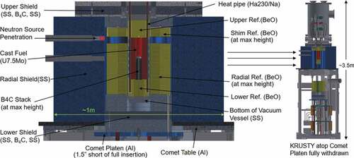
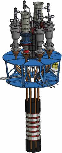
shows a schematic of KRUSTY integrated with COMET. The KRUSTY fuel is highly enriched uranium (HEU) U-8Mo; note that the actual weight fraction of Mo was 7.65%, which will be discussed later. There is 32.2 kg of fuel (27.7 kg of 235U), with an outer diameter (OD) of 11 cm and a total length of 25 cm. The core contains a 4-cm hole to allow the insertion of a 10-kW electric heater for nonnuclear testing and a B4C stack during nuclear testing to simulate the flight start-up rod.
Fig. 2. KRUSTY reactor configuration.
KRUSTY utilizes eight Haynes 230 heat pipes with a nickel wick and sodium working fluid. Thermal bonding of the heat pipes to the core is achieved through a compressive clamping force via an interference fit. The core ring clamps are composed of Haynes 230 heat pipes. The heat pipes transport power to the Stirling converters and simulators. There are two converters that produce electricity and six simulators that mimic the heat removal of the actual converters. From this point on, both the converters and simulators will be referred to as the “Stirlings” unless a distinction needs to be made.
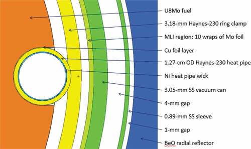
and show MCNP schematics of the core. These schematics were actually the preliminary design drawings of the reactor; i.e., the mechanical designs of the actual components were based on these MCNP schematics.
Fig. 3. MCNP core schematic.
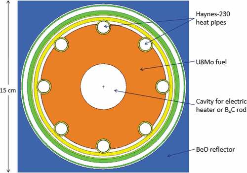
Fig. 4. MCNP schematic of outer core region.
The core is surrounded by multilayer Mo insulation and a Type 316 stainless steel (SS316) vacuum can. There is a 4-mm gap between the vessel and the radial reflector to ensure unimpeded movement as COMET lifts the platen. The KRUSTY neutron reflector is BeO. There are three neutron reflector regions: the platen reflector, the shim reflector, and the axial reflector. A thin stainless steel sleeve is placed on the inside of the BeO stack to ensure alignment and preclude BeO ring contact with the core vessel. This configuration is shown in .
The KRUSTY reactor is surrounded on all sides by shielding, as seen in . The radial shield is Type 304 stainless steel (SS304), while the axial shield contains layers of B4C and SS304. The shielding and all reactor components are discussed in more detail in Sec. VIII.
VIII. KRUSTY REACTOR COMPONENTS
The design and final specifications of the major KRUSTY reactor components are listed below. Although components are specified as either structure, reflector, shield, etc., it is very important to note that all components work in concert to provide structure, reflector, and shielding and thus must be designed integrally. During the design process, changes to a shielding component had significant impacts on structure and reflector design, and vice versa. The only part of the geometry kept constant was the fuel geometry because it had to be fixed early to start the procurement process (although if an unforeseen large reactivity change was needed late in the design process, the fuel length could have been changed without too much additional cost and schedule). This was referred to as our ace in the hole, but fortunately, the design ultimately came together close enough to plan that a fuel design change was not needed.
VIII.A. Fuel
Timely and affordable delivery of fuel was essential to KRUSTY, and U-metal fuel was the only option with infrastructure available to afford success. The fuel was cast and machined at Y-12, which is the only location where the infrastructure and experience existed to fulfill the tight schedule and cost of KRUSTY.
Initially U, UMo, and UZr fuels were considered. Uranium fuel is generally not considered for reactors because of the negative impacts of phase change with temperature, but Kilopower reactors are not intended to undergo many thermal cycles, so it is considered a viable option (a flight reactor will likely stay warm for its entire lifetime). Alloying the fuel slows down the rate of phase change as the fuel passes though transition temperatures; the goal is generally to keep the fuel in its high-temperature gamma phase. The addition of the alloy also increases material strength. For these reasons, alloyed fuel was selected for Kilopower and KRUSTY as a conservative measure. UMo was selected largely because it has the most experience and experimental data of metallic fuels. In addition, for a space reactor Mo is usually better neutronically than Zr (or NbZr) because of low fast neutron capture but moderate epithermal capture, which aids in preventing flooded criticality.
A fuel OD of 11 cm was selected to allow the use of an existing shipping container (the ES-3100, a DOE-approved Type-B container). An inner diameter (ID) of 4 cm allowed the insertion of a 10-kW electric heater for nonnuclear testing and a B4C stack during nuclear testing. The core length was 25 cm and was cast in three parts to allow for simpler casting and machining, largely to simplify criticality safety approvals.
Prior to the HEU casting, Y-12 delivered depleted uranium (DU) castings for prototyping, materials testing, and electrically heated system testing. To expedite delivery and cost, these parts were specified to a very loose tolerance in Mo content, between 7.5% and 8.5%. The parts were delivered at U-7.65Mo. It was then decided to stick with this value and specify 7.65% Mo for the HEU cores, although with a much tighter tolerance. The HEU parts were ultimately delivered with an average of U-7.65Mo.
The total mass of the three KRUSTY fuel parts was 32.20 kg. Two parts were slightly heavier than the other; the measured masses of the three parts after machining were 10.741, 10.741, and 10.718 kg. The reason for the lower-mass piece likely was not atom density but was composition. Three material samples were chemically analyzed from each casting: near the top, at the middle, and near the bottom. All of the measurements from the two high-mass castings (a total of six samples) were very consistent with each other; however, the chemistry measurements for low-mass casting were significantly different. On average, the lower-mass casting was found to have a higher Mo content than the other two (~7.8% Mo versus 7.6% Mo) and a higher carbon content than the other two [~500 parts per million (ppm) C versus 300 ppm C]; this is enough variation to explain the mass/density difference. More so, the top of the low-mass casting was significantly different from the other middle and lower samples (7.83% Mo versus 7.76% Mo) and (740 ppm C versus 500 ppm C). This gave the top end of the low-mass core piece significantly lower neutronic worth; thus, it was important to keep track of the location and orientation of the core parts during assembly.
The uranium isotopics were relatively uniform throughout all samples: 1.0% 234U, 93.1% 235U, 0.5% 236U, and 5.4% 238U. Radiological measurements found no significant Pu [<10 parts per billion (ppb)] and ~1 ppm of 237Np. Note that all percentages used here and throughout the paper are mass percentages and ppm is in units of µg/g unless otherwise noted. There was ~300 ppm of impurities (other than the carbon mentioned above), mostly Si, Fe, and Ni; the content of W was 20 ppm; the content of highly neutron absorbing metals (Dy, Eu, Gd, Sm) was ~1 ppm, and for boron the content was ~1 ppm.
The average density was calculated to be 17.34 g/cm3 under the assumption that the parts were machined exactly to specifications (i.e., to zero tolerance on the drawings). No volumetric measurements were taken because that would have required extra cost and a schedule to arrange for measuring the HEU parts. Bulk dimensional measurement of the fuel castings, height, OD, and ID did indeed match almost exactly at zero tolerance, but approximated measurements of the heat pipe slots indicated there was likely more material present than specified. This would indicate that the actual average fuel density was slightly lower than 17.34 g/cm3, but it was probably no lower than 17.25 g/cm3. In the modeling, the parts were dimensioned at specification, and the 17.34 g/cm3 value was used (conserving mass is most important).
Despite the differences mentioned above, the KRUSTY fuel was well within the overall specification and was considered very well made. Depending on the values used for the theoretical density (TD) of U and Mo, and uncertainties in measurements and chemistry, the fuel was certainly >99% TD. In addition, the geometric tolerances were almost perfect in the most important dimensions (height and diameter), and the level of neutron-absorbing impurities was low.
VIII.B. Heat Pipes
KRUSTY utilized eight heat pipes of 1.27-cm OD to transport heat from the reactor core to the Stirlings. The heat pipe wall was a 0.089-cm Haynes 230 tube, with a thin nickel wick and sodium working fluid. The KRUSTY heat pipes only contained a wick at the lower end, connecting the pool/reservoir region below the fuel to the evaporator region (to just above the top of the fueled height of the core). The rest of the heat pipe operated with thermosiphon action; i.e., fluid return was driven by gravity instead of capillary forces. It would have been preferable to have a full-length heat pipe for several reasons (even for KRUSTY performance, because the thermosiphon flooding limit for this design was rather low), but the design used was quick and inexpensive to fabricate and was “good enough.”
In the adiabatic region the heat pipes had two 45-deg bends, which increased their radial spacing (to simplify the layout of the PCS) and allowed compliance for thermal expansion. The condenser was a funnel shape that mated with the hot end of the Stirlings. The total length of the heat pipes was ~100 cm.
There were a couple of changes in the heat pipe configuration as the design progressed. Initially, the pipes were to be filled with 25 g of Na, and the bottom of the heat pipes was going to be 2.54 cm below the fuel. This gave the Na pool a relatively high neutronic worth because part of the pool was located directly adjacent to the fuel, which reflected neutrons that would have otherwise left the core. This was thought to be acceptable, and perhaps even an advantage, until dynamic modeling was performed. As the heat pipe started up, the pool evaporated, which caused a decrease in reactivity, which again would be acceptable. The problem was that when power removal decreased or stopped, the pool would reform and increase reactivity—this is not a desirable feature, i.e., to have a fission power increase when power removal is lost. The design was thus changed to include only 15 g of Na (thought to provide enough margin after preliminary tests) and for the bottom of the heat pipe to be 7.62 cm below the core (a relatively easy design change). These changes reduced the worth of the pool—and a resulting reactivity change at full power by a factor of 4—and made the effect hardly noticeable in the final test results. In some ways the higher feedback would have been nice because it would have provided some decent data on what was going on internally within the heat pipe (which are data that are extremely difficult to come by), but this change was targeted at a more urgent need: the need to obtain safety approvals. In general, the regulators appreciated when we spelled out all of the design decisions that were made to simplify and/or mitigate potential safety issues with KRUSTY.
VIII.C. Ring Clamps and Compliant Layer
The KRUSTY ring clamps provided both the thermal and structural coupling between the heat pipes and the fuel. The clamping force was achieved via an interference fit; i.e., at room temperature the ring clamp ID was smaller than the OD defined by the outside of the heat pipes. The clamps were Haynes 230 with a 12.13-cm OD and a thickness of ~0.3 cm (they were not of uniform thickness), with small indents for the heat pipes and other contours to relieve stress.
Several options were considered for bonding, including a braze or diffusion bond, but the clamping force was considered the easiest to implement. One of the biggest KRUSTY challenges was deciding where/how to mate the fuel with the rest of the system. It would have been extremely difficult to ship an assembled HEU system to the NNSS because of the time and cost it would take to get a shipping container/method approved. Alternatively, NCERC did not have substantial manufacturing infrastructure on-site to aid in assembly. The solution was to design and build specialized components (a heater and alignment fixture) that could be transported to and used within the DAF to complete system assembly. The ring clamps were installed by warming them to ~800°C with a specialized heater and then sliding them over the heat pipes with the aid of a specially designed alignment fixture. Once the clamps cooled, they firmly pressed the heat pipes against the fuel.
Before the clamps were installed, a layer of thin Cu foils was placed between heat pipes and the fuel. This Cu helped prevent mass diffusion/transfer between the UMo and the Haynes 230, which is expected to chemically interact under direct contact at 800°C. Another reason for adding the Cu layer was to provide a soft material that would facilitate heat transfer between the two surfaces. Heat transfer can be very difficult in a vacuum, but it was felt that a high compressive force applied across a compliant layer would be sufficient. Significant laboratory-scale testing and electrically heated system testing subsequently verified that this clamping technique provided excellent thermal bonding between the heat pipes and fuel.
shows a drawing of the KRUSTY assembly.
Fig. 5. KRUSTY in-vacuum components.
VIII.D. Multilayer Insulation
Another significant design issue for KRUSTY, or any low-power, high-temperature reactor, was to minimize passive heat loss (to maintain adequate thermal efficiency). This is contrary to traditional nuclear reactors, where designers do all they can to encourage passive heat losses (to release decay heat). Operating in a vacuum is a good start for preventing thermal losses, but at 800°C it does not take much surface area to generate kilowatts of power loss, even with low emissivities. Traditional insulating materials are not suited for space reactors because of mass, but, even more so, they are not suited because of the relatively large thickness required (larger gap sizes are detrimental to neutronics). Multilayer insulation is preferred because it can create several radiation gaps in a very small space for a very low mass and is therefore used in most space systems.
The KRUSTY MLI was 25.4-μm-thick (1-mil-thick) Mo foil, separated by a 101.6-μm-thick (4-mil-thick) weaved thread of fused quartz, which limits potential contact between the foils while minimizing conduction. Molybdenum was the ideal choice for the MLI because of low-emissivity, high-temperature capability and acceptable neutron absorption. Three regions within the reactor utilized MLI: 8 layers between the fuel/clamps and the vacuum can, 4 layers between the fuel and the axial reflectors, and 16 layers around the heat pipes (except in the fueled region). There was also much MLI used in the PCS.
VIII.E. Vacuum Can
The KRUSTY vacuum can, sometimes referred to as the core can, is an extension of the large vacuum chamber that contains the PCS. Creating a vacuum was essential to meeting the goals laid out for KRUSTY. Kilopower reactors are intended to operate in space, and the thermal performance of the system would not have been prototypic without operating in a vacuum. More importantly, the U-8Mo fuel would have reacted significantly with air at 800°C. The vacuum can also serve as the supporting structure for the lower axial reflector and the core; as the system thermally expands, it is the bends in the heat pipes that relieve the stress.
The vacuum can was 0.305-cm-thick SS316, with an OD of 13.3 cm and an axial length of 52.5 cm. At the top end it was bolted to the protruding lower flange of the vacuum chamber. The bottom of the can was designed to allow for easy removal of the end cap, via eight bolts. This end cap had a boss that provided the support for the lower axial reflector plugs and contained a threaded hole for the rod/spindle that was used to center B4C rod pieces and/or attach the neutron source (if either or both were used).
VIII.F. B4C Rod
The B4C rod is actually a stack of several B4C disks or pucks. The pucks contain a small central hole so they can be slid over the top of a central spindle that was threaded into the vacuum end cap. The height of the stack could then be changed manually between tests, to measure the neutronic worth of a flight prototypic control rod. The pucks were 96% enriched 10B4C, to maximize neutronic worth, as is intended for flight design. The average density of the puck material was 2.15 g/cm3, or about 90% TD.
VIII.G. Neutron Reflector
The neutron reflector material selected for KRUSTY was BeO, specifically Thermalox® 995 (Materion Corporation). BeO creates the highest-worth reflector, which allows robust reactivity margins for safety and operation, as well as low fuel mass and flight system mass. There were three neutron reflector regions: the platen reflector, the shim reflector, and the axial reflector.
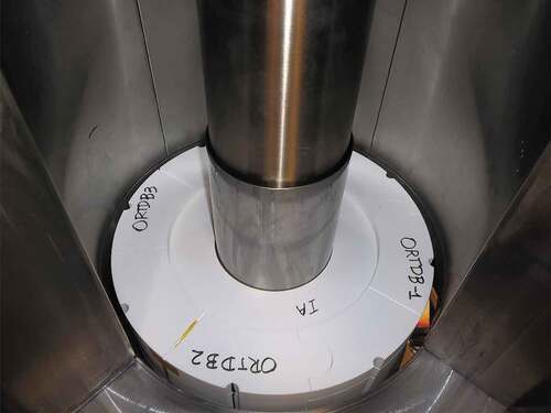
The platen and shim reflectors both utilized a stack of BeO rings, with a 14.5-cm ID and a 38.1-cm OD. To utilize existing fabrication machinery, each ring was split into five pieces: an inner ring and four “puzzle” pieces to form the outer ring. Most of the rings had a thickness of 2.54 cm, which was preferable for fabrication/cost and handling/assembly. Thinner rings, 0.312 and 0.625 cm, were also manufactured to allow smaller reactivity adjustments; the rings were added incrementally as the KRUSTY approach to critical was conducted. Some of the outer puzzle pieces contained a groove that allowed thermocouples to be placed within the radial reflector. The platen reflector pieces were stacked around a 0.086-cm-thick Type 321 stainless steel centering ring. This structure helped align the pieces and maintained the gap between the vacuum can and radial reflector; avoiding the possibility of a BeO piece protruding into the gap and perhaps binding to or damaging the vacuum can. This configuration is shown in . The small semicircle slots on the outside of the puzzle pieces were intended for support rods that would clamp the BeO rings together axially, but it was later determined that these rods (and the associated clamp hardware) were not required, so they were not used during the testing. Some yellow tape that holds in a thermocouple can also be seen in .
Fig. 6. KRUSTY BeO puzzle pieces, centering ring, and vacuum can, surrounded by radial shield.
shows that the radial reflector was divided into two axial regions. The platen region (which was raised and lowered by COMET) could contain up to 12 full rings, and the shim region (permanently affixed to the shield) could hold up to 2 full rings. This split reflector design presented the biggest and most arduous KRUSTY design change. Initially, it was thought that KRUSTY had to be more than 1 $ cold-subcritical following a 7.62-cm drop of the COMET scram system. It was later discovered (thankfully, in time) that the system must be subcritical with only a 3.81-cm reflector drop (i.e., only one of the two parallel 3.81-cm energized rams would drop). This created a design issue because the first 3.81 cm of reflector drop occurred when the top of the reflector was above the fuel, which caused the neutronic worth to be very low compared to the second 3.81-cm drop (when the top of the reflector was directly outside of the fuel). The reactor could have been redesigned in various ways to meet the 3.81-cm requirement, but since the reflector and axial shield components had been ordered, it was decided to statically attach the top portion of the reflector to the upper shielding, in what was ultimately called the shim pan.
Previously, the system reactivity would have been shimmed by changing the height of the platen reflector, but now the bulk of the shim would be implemented by changing the height of the BeO in the shim pan. The presence of the shim reflector created several headaches: a potential safety issue of the pan falling and creating a reactivity insertion, an unwanted radiation streaming path, complication of reflector temperatures due to a shortcut for air to circulate mid-reflector, thermal decoupling of the shim BeO, and a significant increase in the difficulty of adjusting the BeO stack. In the end, only bulk shim was performed with the shim reflector, and smaller shim was performed on the platen reflector, which exacerbated the streaming and thermal issues because the platen stack was not fully loaded for the final test as was intended. Fortunately, the agility of the design team and design process allowed us to complete this design change within cost and schedule, without major negative impact to the testing and data.
also shows the upper and lower axial BeO reflectors. The axial reflectors were 10.16 cm in height. The upper reflector was fabricated as one 10.16-cm piece, with slots machined to accommodate the heat pipes and MLI. The upper reflector also had a small hole drilled into the end that faced the core, to center the rod/spindle that supported the neutron source (when used).
The lower axial reflector was split into four pieces. It was split radially (inner and outer) to allow access to the central fuel cavity, which was used for inserting the electric heater, inserting and changing the height of the B4C control rod stack, and/or swapping the neutron source in or out. Each of these radial pieces was then split in two axially, into upper and lower 5.08-cm pieces. The reason for this was to allow for different materials to be swapped in and out of the assembly to measure neutronic worth (to benchmark neutron cross sections) during the component criticals.
There was no MLI placed around the perimeter of the axial reflectors, i.e., between the BeO and SS316 vacuum can. This was optimal from the neutronic perspective and allowed a path for passive heat loss from the system, which was an added precaution for decay heat removal, which was never actually close to being a significant issue. Several layers of MLI were placed between the fuel and each of the axial reflectors to prevent material interaction and also to thermally decouple the fuel to keep passive thermal losses from being excessive.
VIII.H. Shielding
The shield design for KRUSTY presented several challenges because of the need to balance reactivity effects, thermal issues, dimensional constraints, mass limits, cost, and fabricability. The purpose of the shield is to prevent activation to the room, i.e., to keep it “clean” for future sensitive measurements, and to reduce dose rate to prevent single-event upsets in active electronics and components.
A hydrogenous neutron shield, such as polyethylene, was eliminated due to its low temperature limit (~100°C). Lithium hydride was deemed to have too much programmatic risk from a cost and schedule perspective. Borated stainless steel was found to be high cost with limited availability. High-iron-content steel (low Ni, Mo) was low cost but did not provide adequate neutron shielding. A layered SS316/B4C shield was found attractive, but the cost/complexity was problematic for the radial shield, so a solid stainless steel design was used. The final design used a solid SS304 radial shield; however, the axial shield was required to utilize the SS304/B4C layers to meet dimensional constraints. Initially, the design called for SS316 for all shield components, but it was not used after it was found that SS304 provided simpler procurement and lower cost, although SS304 is not quite as an effective neutron shield as SS316 (less Ni and Mo to capture neutrons).
The radial shield, depicted in blue in and surrounding the BeO in , was by far the heaviest KRUSTY component, with a mass of ~3500 kg. As discussed above, a lighter shield could have been used, but this simple, low-cost approach was used because COMET was able to accommodate the size and mass. The radial shield was fabricated in segments of four round quarters; in retrospect it might have been better to use more pieces, provided that streaming paths were prevented. As seen in , one quarter was rigged as a door to allow access for the installation and modification of KRUSTY, e.g., to change the amount of BeO in the shim pan. These SS304 quarters are 63.1 cm tall with a 101.9-cm OD and a 41.0-cm ID. The quarters were installed on a 2.57-cm AISA4140 centering plate, which served as the mounting interface between the COMET table and the shield, and facilitated the moving of the shield door and other operations. Two penetrating cylindrical ports were machined into one of the quarters to allow the insertion of a neutron source; these ports were plugged with corresponding inserts when not in use. shows the design drawing of the four round quarters on the centering plate, with the door open.
Fig. 7. Design drawing of radial shield.
Axial shielding was strategically placed wherever space was available. Height limits on the assembly (resulting from ceiling height, forklift parameters, platen travel, etc.) required a more volume-effective material than SS304 to be used for neutron shielding. Axial layers of B4C were used as this additional neutron shielding. Unfortunately, the delivered B4C plates were well below specification; they were specified at 90% TD but were delivered at only ~75% TD. It was decided not to hold up the schedule to wait for replacement parts. Fortunately, the pieces were so thick, and the thermal neutron cross section of boron is so high that this density change was not a major problem (but lower density did in fact decrease fast neutron and gamma shielding).
Lower axial shielding was installed directly on the COMET platen, which is a 2.54-cm-thick aluminum lift table. The shielding on the platen, referred to as the platen shield, consisted of several 2.54-cm-thick, 39.7-cm-OD cylindrical plates. Two solid B4C plates were stacked on top of three SS304 plates. The B4C plates were intentionally positioned closer to the core to reduce the number of thermal neutrons that could create high-energy gammas in the SS304. Four SS304 annular plates were then placed on top of the B4C plates. These plates had a 14.3-cm ID in the center, so they could move up past the core vacuum can. These plates served as the support for the radial reflector and its centering ring. The vacuum can’s bottom also provided significant axial shielding, ~3.8 cm of SS316, as well as the support on which the lower axial reflector rested.
Upper axial shielding was provided by several components. The bulk of the upper shielding was composed of the leveling plates. These plates were of rectangular geometry, and they were placed on top of the radial shield quarters and served as the support for the large vacuum vessel. A 1.27-cm SS304 lower plate was placed on top of the radial shield followed by a 5.08-cm B4C plate and then a 3.08-cm SS304 upper leveling plate. A 6.35-cm-thick SS304 ring shield was mounted to the bottom of the lower leveling plate to shield the region above the radial reflector and serve as the mounting points for the shim pan.
Inside of the vacuum can, plug shields were stacked atop the upper axial reflector: First came a 3.81-cm-thick SS304 plug shield followed by a 5.08-cm B4C plug shield that included a step change to a larger radius at the transition from the vacuum can to the vacuum flange, which was followed by an 8.89-cm SS304 uppermost plug shield. Each of these plug shields, also referred to as bore shields, contained eight outer radial slots to accommodate the heat pipes and their corresponding MLI. There was also a gap above the vacuum vessel flange that was filled with a 3.81-cm B4C ring/collar shield.
The upper axial shielding also included a 3.81-cm-thick SS304 cylindrical shield that rested on the bottom of the vacuum chamber. There was an aluminum plate/strut structure with a flight shield–like geometry placed on top of this shield (blue in ) that served to align the heat pipes and the Stirlings; however, instead of being filled with shield material, this region was packed full of the numerous instrumentation components and wires used on KRUSTY. The last bits of upper axial shielding were B4C planks that were inserted into the fork guides after the forklift had lifted and were installed in the vacuum assembly atop the radial shield.
IX. KRUSTY REACTOR DESIGN CALCULATIONS
KRUSTY calculations were targeted to keep KRUSTY as prototypic as possible to a 5-kW(thermal) Kilopower concept generated in 2012 while meeting all of the requirements and goals mentioned previously. Several major design modifications were required to test in a vacuum on the COMET assembly, and the addition of realism to the design (e.g., actual tolerances, material specifications, etc.) also required several design iterations. Fortunately, very little changed between the flight concept and KRUSTY with respect to the core; the fuel and heat pipe geometries have remained unchanged since their inception.
Throughout the design process, numerous neutronic, thermal, and structural calculations were performed and updated as the design progressed. Many of the final design calculations will be included in follow-on benchmark papers so that they can be compared to actual results.
Criticality safety calculations were performed to show that the fuel could not go critical under any credible scenario, except being surrounded by beryllium or another fissile material. This is not surprising because the Kilopower reactors are designed to remain subcritical during all launch accidents (immersed in water, sand, etc.), which is accomplished with a beryllium reflector of very high neutronic worth. The criticality safety results are in and were intended to be bounding for any possible combination of people, equipment, and feasible materials.
TABLE I Criticality Calculations for Various Hypothetical Configurations
One of the biggest KRUSTY design challenges was to ensure enough excess reactivity to achieve full temperature while also meeting criticality safety requirements (during casting, machining, transport, handling, and ultimately testing). Also, if the as-built reactivity was too high, the system would not operate with enough BeO reflector in place to be prototypic or to shield the room effectively. Alternatively, a generous amount of margin was desirable because of the neutronic uncertainty in highly reflected beryllium systems and temperature reactivity defect.
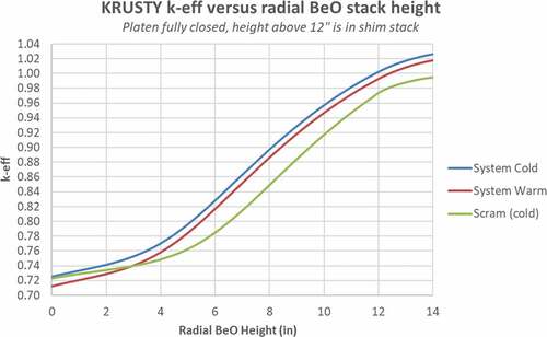
shows predicted keff as a function of radial reflector height with the platen completely closed. The warm values in are at full temperature and power. The scram values assume that the platen drops 1.5 in. and the system cools off to its most reactive state.
Fig. 8. The keff versus radial reflector height.
Zero-power criticals were used to determine what BeO height to use for the final KRUSTY run. Reactivity was then inserted by raising the platen so that the BeO surrounded the core. The reactivity versus platen height calculations for the pretest nominal BeO loading are shown in .
Fig. 9. KRUSTY reactivity versus platen position (with pretest nominal BeO loading).
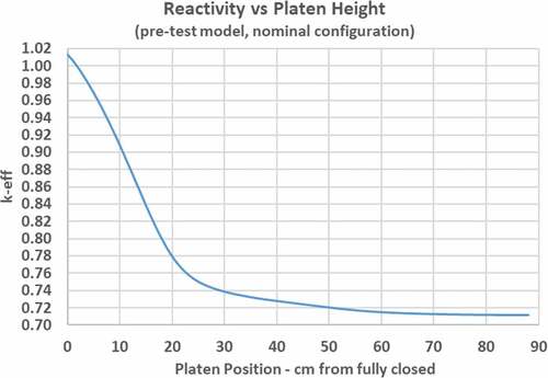
The full length of the platen travel is 88 cm, which is the position of the platen while modifications are made to KRUSTY (e.g., adding or removing BeO from the platen and shim stacks, changing the B4C stack, moving the neutron source, etc.). shows that the reactivity does not rise significantly until the platen is ~20 cm from fully closed, and KRUSTY does not go critical until only a few centimeters from closed.
The transient code FRINK was used to model reactor operation. The key inputs to FRINK other than basic material properties (heat transfer coefficients, expansion coefficients, specific heats, etc.) are the kinetics parameters, reactivity coefficients, power depositions/profiles, and thermal coupling between components.
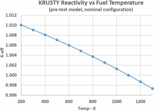
Reactivity feedback is largely determined by thermal expansion of the fuel. Fuel heating causes ~95% of the net reactor feedback, and ~90% of this fuel feedback is caused by thermal expansion (~10% is caused by changes in fuel cross sections). Reactivity is plotted versus fuel temperature in .
Fig. 10. Component temperature-dependent reactivity worth.
Reactivity feedback was also calculated for the axial reflector, heat pipes, core brackets, vacuum can, radial reflector, and shield. The feedback for each component is input into FRINK as a polynomial of neutronic worth versus temperature. During a transient, the net feedback is calculated as the difference in worth between the component’s starting and current temperatures. In some reactors, component reactivity worth can be significantly affected by the thermal state and configuration of other/adjacent components (especially externally moderated systems). For KRUSTY, several different combinations of reactor states were calculated, and the impact of the overall reactor state was minor on each component’s individual feedback.
shows the temperature defect of each component or the change in reactivity as that component heats from room temperature to operating temperature. The reactivity is reported in cents, based on a beta-effective of 0.00688, as calculated by MCNP.
TABLE II Reactivity Feedback of Reactor Components
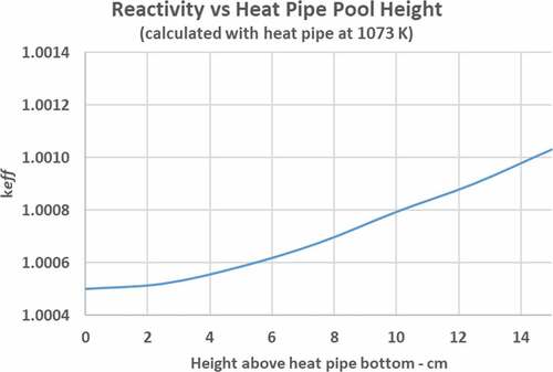
As mentioned previously the Na pool has reactivity worth as well, which is dependent on the temperature and pool height. shows the worth of the Na pool when the reactor is at operating temperature. This curve is used to calculate the reactivity change with the estimated change in pool height as the power throughput rises or falls. At higher powers more Na will be looping through the heat pipe; thus, the pool will be lower, and vice versa.
Fig. 11. Reactivity as a function of heat pipe pool height.
Power deposition was calculated in all regions of the system. The average power density in the fuel is ~2 W/cm3 at a reactor power of 4 kW(thermal). In the fuel, the radial power peaking is very small, except for peaking in a very thin region around the perimeter of the fuel (due to moderated neutrons returning from the reflector). This peaking is insignificant from a heat transfer perspective but will have to be considered if fuel burnup starts to approach limits. The axial power peaking is modest and is a function of platen position, as shown in .
Fig. 12. Axial peaking factor in the KRUSTY fuel.
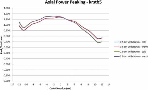
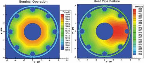
The overall axial peaking factor of 1.15 is very small compared to most reactors (because of a large neutron-free path relative to core length) despite the fact that KRUSTY has an extremely large fuel length-to-diameter ratio. The squiggles in indicate the effects of the core clamps. Five relative power peaks occur at the locations between the clamps, where more moderated neutrons can reach the fuel. However, these peaks are ~1% of power, so the net impact is minor. Closing the platen from 2.0 to 0.5 cm reduces the axial peaking by preventing leakage at the top end of the fuel, by narrowing the BeO gap between the platen and shim radial reflectors. The cold and warm power profiles are almost identical because of the fast spectrum, which simplifies analysis. The power depositions from MCNP were then used to calculate reactor temperatures within FRINK. displays two temperature contour plots at the core axial centerline: one for nominal operation and the other for a failed heat pipe.
Fig. 13. KRUSTY core temperature calculations at axial center.
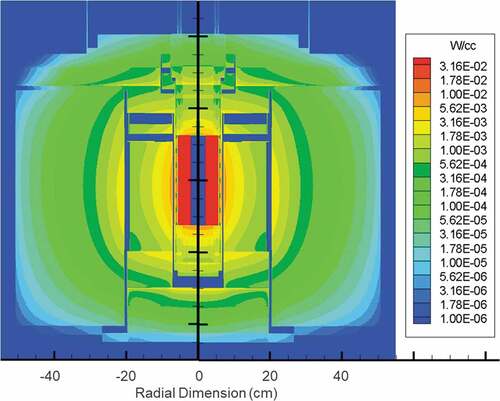
The power density in “ex-fuel” components is shown in . Note that an arbitrary band of green contour is made darker to provide better delineation between power density levels (each band depicts a factor of 1.78). The blue regions are void, so axial gaps above the platen stack, shim stack, lower shield, and platen are all visible. Regions that contain B4C in the upper and lower shields are indicated by higher power deposition levels than the surrounding steel.
Fig. 14. Systemwide (ex-fuel) power density at 4 kW(thermal).
The total power fraction in each component is shown in .
TABLE III System Power Deposition Fractions
KRUSTY is so compact that only 93.7% of the recovered fission power ultimately ends up in the fuel. The radial shield captures most of the energy leaving the system and thus has the highest total power deposition. The radial reflector is a bit lower because it does not capture nearly as many gammas, even though it also gains energy from slowing down neutrons via scattering.
As the design process progressed, several empirical correlations were added to the analysis as prototyping and electrical testing were completed. One of the biggest challenges of designing and modeling KRUSTY was the thermal coupling of components within the vacuum chamber. The biggest uncertainty was heat transfer from the heat pipes to the fuel and to the core clamps as well as the heat flow from the heat pipes to the Stirling engine working fluid. Data from electrically heated testing were used to empirically tweak heat transfer parameters.
X. SUMMARY
KRUSTY was a prototypic nuclear-powered test of the 5-kW(thermal) Kilopower space reactor. The goal of the KRUSTY design was to demonstrate the performance of the reactor power system and show that space fission technology can be developed affordably. In March of 2018, KRUSTY did indeed operate successfully and achieve all of the primary goals laid out in this paper.
Acknowledgments
We would like to thank the entire Kilopower team for its commitment to realizing the first demonstration of space fission power technology in over 50 years. We would also like to thank NASA’s Space Technology Mission Directorate and Game Changing Development Program, as well as the DOE National Nuclear Security Administration, Nuclear Criticality Safety Program, for their sponsorship and vision in seeing the Kilopower technology through to the conclusion of its first groundbreaking step toward abundant, affordable power for space missions to the solar system’s most challenging and interesting locations.
References
- D. I. POSTON et al., “Experimental Demonstration of a Heat Pipe–Stirling Engine Nuclear Reactor,” Nucl. Technol., 188, 3 (2014); https://doi.org/10.13182/NT13-71.
- P. R. McCLURE et al., “Kilopower Project: The KRUSTY Fission Power Experiment and Potential Missions,” Nucl. Technol., 206, S1 (2020); https://doi.org/10.1080/00295450.2020.1722554.
- M. A. GIBSON et al., “Heat Transport and Power Conversion of the Kilopower Reactor Test,” Nucl. Technol., 206, S31 (2020); https://doi.org/10.1080/00295450.2019.1709364.
- P. R. McCLURE et al., “KRUSTY Experiment: Reactivity Insertion Accident Analysis,” Nucl. Technol., 206, S43 (2020); https://doi.org/10.1080/00295450.2020.1722544.
- R. SANCHEZ et al., “Kilowatt Reactor Using Stirling TechnologY (KRUSTY) Component-Critical Experiments,” Nucl. Technol., 206, S56 (2020); https://doi.org/10.1080/00295450.2020.1722553.
- T. GROVE et al., “Kilowatt Reactor Using Stirling TechnologY (KRUSTY) Cold Critical Measurements,” Nucl. Technol., 206, S68 (2020); https://doi.org/10.1080/00295450.2020.1712950.
- D. I. POSTON et al., “Results of the KRUSTY Warm Critical Experiments,” Nucl. Technol., 206, S78 (2020); https://doi.org/10.1080/00295450.2020.1727287.
- D. I. POSTON et al., “Results of the KRUSTY Nuclear System Test,” Nucl. Technol., 206, S89 (2020); https://doi.org/10.1080/00295450.2020.1730673.
- D. B. PELOWITZ, “MCNP6 User’s Manual,” LA-CP-11-1708, Los Alamos National Laboratory (2011).
- D. I. POSTON and H. R. TRELLUE, “User’s Manual, Version 1.00 For Monteburns, Version 3.01,” LA-UR-98-2718, Los Alamos National Laboratory (June 1998).
- D. I. POSTON et al., “FRINK—A Code to Evaluate Space Reactor Transients,” AIP Conf. Proc., 880, 449 (2007); https://doi.org/10.1063/1.2437485.
- D. I. POSTON et al., “A Simple, Low-Power Fission Reactor for Space Exploration Power Systems,” presented at American Nuclear Society Topl. Mtg. Nuclear and Emerging Technologies for Space (NETS-2013), Albuquerque, New Mexico, February 25–28, 2013.