
 ?Mathematical formulae have been encoded as MathML and are displayed in this HTML version using MathJax in order to improve their display. Uncheck the box to turn MathJax off. This feature requires Javascript. Click on a formula to zoom.
Abstract
This paper demonstrates a multiphysics solver for pebble-bed reactors, in particular, for Berkeley’s pebble-bed -fluoride-salt-cooled high-temperature reactor (PB-FHR) (Mark I design). The FHR is a class of advanced nuclear reactors that combines the robust coated particle fuel form from high-temperature gas-cooled reactors, the direct reactor auxiliary cooling system passive decay removal of liquid-metal fast reactors, and the transparent, high-volumetric heat capacitance liquid-fluoride salt working fluids (e.g., FLiBe) from molten salt reactors. This fuel and coolant combination enables FHRs to operate in a high-temperature, low-pressure design space that has beneficial safety and economic implications. The PB-FHR relies on a pebble-bed approach, and pebble-bed reactors are, in a sense, the poster child for multiscale analysis.
Relying heavily on the MultiApp capability of the Multiphysics Object-Oriented Simulation Environment (MOOSE), we have developed Cardinal, a new platform for lower-length-scale simulation of pebble-bed cores. The lower-length-scale simulator comprises three physics: neutronics (OpenMC), thermal fluids (Nek5000/NekRS), and fuel performance (BISON). Cardinal tightly couples all three physics and leverages advances in MOOSE, such as the MultiApp system and the concept of MOOSE-wrapped applications. Moreover, Cardinal can utilize graphics processing units for accelerating solutions. In this paper, we discuss the development of Cardinal and the verification and validation and demonstration simulations.
I. INTRODUCTION
The U.S. Department of Energy’s (DOE’s) Nuclear Energy (NE) Center of Excellence (COE) for Thermal Fluid Applications in Nuclear Energy,Citation1 inaugurated in April 2018, researches novel solution strategies for historically challenging issues involving fluid flow in nuclear reactors. These include issues that still plague the current fleet of deployed light-water reactors (LWRs) and fluid-flow and fluid-related phenomena related to advanced reactor technologies. Advanced reactors include small modular reactor concepts, microreactors, and advanced reactor concepts utilizing coolants such as liquid metal, molten salts, or gas reactors. The new solution strategies and algorithms are implemented using modern software design methodology and best software quality practices to deliver validated Nuclear Quality Assurance 1–level software to the nuclear power community.
Our advanced thermal-fluids research and development approach synergistically combines three natural, overlapping length and time scales in a hierarchal multiscale approach to avoid the temptation and pitfalls of attempting to develop a single solve-all algorithm for physical fluid-flow problems that will span nine orders of magnitude in spatial and temporal scales. A more tractable approach is grouping physics with similar multiscale requirements into a common algorithm, developing separate software applications to address the separate scales, and coupling the appropriate applications. This multiscale modeling and simulation template has proven to be highly successful in the Nuclear Energy Advanced Modeling and Simulation (NEAMS) program to simulate nuclear material evolution under irradiation.Citation2 The three overlapping thermal-hydraulic scales are defined across all reactor concepts as follows:
Lower length scale: The lower length scale will resolve high-resolution physics associated with single and multiphase, highly turbulent conjugate heat transfer (CHT) with highly resolved thermal boundary layers (heat flux).
Engineering length scale: The engineering length scale will integrate coarse-mesh approaches for homogenized multidimensional CHT, such as those found in gas-cooled pebble-bed reactors, or three-dimensional (3-D) subchannel capabilities tightly coupled to nuclear fuel performance.
System scale: System-scale analysis for nuclear reactors is composed of one-dimensional fluid-flow pipe networks and zero-dimensional system components. These classes of algorithms and corresponding approaches are treated as reduced-order models (ROMs) of the more complex scales and allow for more efficient calculations. These reduced-order systems rely heavily on empirical correlations or models since many of the flow features and phenomena are no longer resolved.
We note that, despite the analogy in template, motivation, and structure, the individual scales have a markedly different meaning than in materials modeling.Citation2 For example, in the fuel-modeling approach adopted in NEAMS, the continuum-mechanics modeling of the fuel pellet represents actually the engineering scale, while lower-length-scale models refer to atomic interaction or molecular dynamics. The thermal-hydraulic multiscale template described previously, however, aims at modeling the full power plant, a system that is several orders of magnitude larger than a pellet. Therefore, in the multiscale template of the COE, the detailed modeling of the flow structures and related heat transfer by the means of computational fluid dynamics (CFD) is considered the lower length scale, while the engineering and plant scale adopt various forms of homogenization. We also note that, in a multiphysics simulation, CFD will couple with physics that exhibit similar resolution.
To demonstrate the multiscale philosophy of the COE, we focus first on flouride-salt-cooled high-temperature reactorsCitation3 (FHRs). The FHR is a class of advanced nuclear reactors that combines the robust coated particle fuel from high-temperature gas-cooled reactors, the direct reactor auxiliary cooling system passive decay heat removal of liquid-metal fast reactors, and the transparent, high-volumetric heat capacitance liquid-fluoride salt working fluids (e.g., FLiBe) from molten salt reactors.
This combination of fuel and coolant enables FHRs to operate in a high-temperature, low-pressure design space that has beneficial safety and economic implications. In 2012, the University of California-Berkeley was charged with developing a preconceptual design of a prototype FHR: the pebble-bed fluoride-salt-cooled high-temperature reactorCitation4 (PB-FHR). The Mark 1 design of the PB-FHR (Mk1 PB-FHR) is a 236-MW(thermal) FLiBe-cooled pebble-bed nuclear heat source that drives an open-air Brayton combined-cycle power conversion system. The PB-FHR’s pebble bed consists of a 19.9% enriched uranium fuel core surrounded by an inert graphite pebble region that shields the outer solid graphite region, core barrel, and reactor vessel. The fuel reaches an average burnup of 178 000 MWd/tonne. We note that the Mk1 PB-FHR exhibits strong negative temperature reactivity feedback from the fuel, graphite moderator, and FLiBe coolant, but a small positive temperature reactivity feedback from the inner and outer graphite reflector pebble regions.Citation4
Flouride-salt-cooled high-temperature reactor pebble beds are comprised of hundreds of thousands of pebbles, and a CFD-grade detailed description of the flow field through these pebbles for an entire reactor core is not practical with current simulation technology. However, this paper will demonstrate a credible pathway toward a full-core, predictive, high-fidelity CFD capability for these reactors. For practical, fast-running, design-related purposes, porous media formulations have been employed in codes such as THERMIX (CitationRef. 5) and AGREE (CitationRef. 6). However, simple porous media approximations are often incapable of capturing the flow field’s critical details, such as the wall-channeling effect due to the change in porosity near the vessel walls. Advanced formulations for the engineering scale can address these issues, but data from finer-scale simulations are needed to build closure relationships. Such advanced formulations are being implemented in Pronghorn,Citation7–9 the engineering-scale platform of the COE. We note that finer-scale calculations are also needed to analyze local temperature peaking and fuel temperatures.
Fine-scale CFD simulations have been attempted before (e.g., CitationRef. 10), but not for large-scale beds using large eddy simulation (LES). In contrast to commonly used Reynolds-averaged Navier-Stokes methods, LES and direct numerical simulation (DNS) provide a much lesser degree of modeling uncertainty, and they can provide valuable and unprecedented insight into the flow physics. In fact, in LES a broad range of scales of motions associated with turbulence are resolved rather than being modeled. This work represents the most extensive collection of LES ever attempted for pebble beds with a random distribution.
One concept for an overall multiphysics strategy for FHR simulation is illustrated in . A systems analysis tool for advanced reactors with coolants in the liquid phase, called SAM (CitationRef. 11), drives the simulation of the engineering-scale tools (Pronghorn and Rattlesnake/MammothCitation12). The lower-length-scale tools can be run concurrently to provide dynamic closures for the engineering scale or offline to produce correlations (which would be more likely). The lower-length-scale simulator may comprise neutronics [e.g., OpenMC (CitationRef. 13)], thermal fluids [Nek5000-NekRS (CitationRef. 14)], and fuel performance [BISON (CitationRef. 15)].
Fig. 1. Diagram showing the multiscale structure of the COE simulator for FHRs
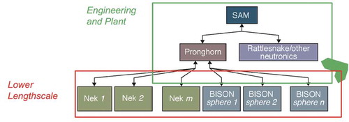
Cardinal, the tool developed here, is the COE tool for lower-length-scale simulation for pebble beds. This new platform tightly couples all three physics and leverages advances in MOOSE (CitationRefs. 16 and Citation17) such as the MultiApp system, and the concept of MOOSE-Wrapped-AppCitation18 (MWA). Moreover, it is designed from the ground up to scale on massively parallel architectures and perform well on supercomputing architectures. Initial efforts in the development of Cardinal were presented in a recent report.Citation19 In this paper, we provide a significant advancement to the high-fidelity modeling of FHR pebble beds. We also demonstrate a hybrid graphics processing unit (GPU)–CPU model to leverage pre-exascale supercomputer architectures (i.e., Summit) and the potential of scaling to full-core simulations in the near future.
In this manuscript, we
describe the design and structure of Cardinal
discuss verification and validation
demonstrate the application of Cardinal to large-scale pebble beds.
We emphasize the importance of the data generated with these high-fidelity CHT simulations of pebble beds. They represent an essential stepping stone for developing closure models for Pronghorn (e.g., models including the wall-channeling effects), and in general, a resource for confirmatory analysis of ROMs. While we do not focus here on using the data generated to extract closure relationships, this will be the subject of future publications.
II. CARDINAL
MOOSE was initially developed for solving fully coupled systems of partial differential equations (PDEs) using fully implicit time stepping. To utilize MOOSE, developers create small C++ objects representing their PDEs, boundary conditions, initial conditions, etc. MOOSE then coordinates PETSc and libMeshCitation20 to perform a Newton solve over all of the physics to find the solution to the multiphysics problem. While this is still the primary way to use MOOSE, the library has also gained capability for loosely coupled solves, Picard iteration, and even coupling to external applications (such as OpenMC and Nek5000). In Secs. II.A and II.B, we discuss the MultiApp features of MOOSE used in Cardinal. A new MOOSE-based application was createdCitation19 that compiles all of the codes into one executable. For the previous study, that code was named Cardinal and combined BISON, OpenMC, and Nek5000 to achieve high-fidelity simulation of FHR reactors.
II.A. MOOSE-Coupling Capability
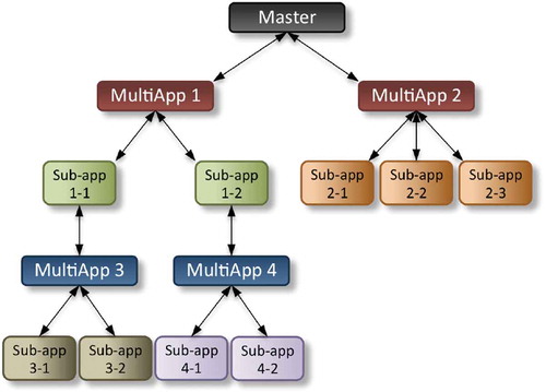
The MultiApp system within MOOSE allows for arbitrary depth, hierarchical execution of applications in parallel.Citation18 As shown in , a MultiApp solve will always have a master application. Underneath that master application can be an arbitrary number of MultiApp objects. The MultiApp objects are containers of instances of applications and can have many instances of that application. As an example, the master application might be a neutron transport simulator for LWRs and have one MultiApp representing the fuel rods with that MultiApp having thousands of instances of a fuel performance simulation tool, one for each fuel rod. Each subapplication itself can have any number of MultiApps, leading to an arbitrarily deep tree of applications. These application instances are spread out in parallel, and all subapplications within an individual MultiApp are executed simultaneously (given enough computing resources).
Fig. 2. MultiApp structure
A key feature of MOOSE to Cardinal is that a MultiApp can hold non-MOOSE-based (external) applications. This is possible using the MWA interfaces. By creating a few objects that wrap an external application and present it to MOOSE as a MOOSE-based application, that external application can then be placed into any point in the hierarchy. For the current effort, OpenMC and Nek5000 were wrapped in the MWA interfaces, allowing them to participate in a MultiApp solve. For each application, the following interfaces were developed:
ExternalApp: Derives from MooseAppBase and is the basic wrapper to the code the MultiApp system needs.
ExternalProblem: Derives from Problem to implement a solver call, which in turn calls the external code and creates data fields.
ExternalMesh: Derives from MooseMesh to create a mesh that is compatible with the external application.
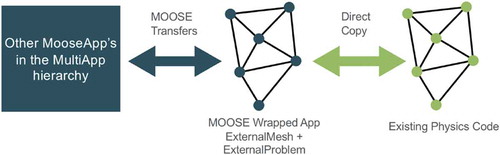
While MultiApp creates trees of executing applications, transfers are needed to move data between them. Transfers move data only vertically, up and down the hierarchy of applications. Many different types of transfers exist, including interpolation projection, evaluation, data copy, post-processor transfer, and scalar variable transfer. Consistent data transfers between dissimilar applications pose challenges for massively parallel code execution. To address this issue, the MWA system utilizes an ExternalMesh that is created to be compatible with the third-party application. Fields/values can then be easily moved to the ExternalProblem that uses the ExternalMesh. Built-in MOOSE transfers can communicate values with any other MOOSE/non-MOOSE application in the MultiApp hierarchy. Examples of data that can be transferred include fields, reduced values (average, minimum, maximum, etc.), and parameters. A schematic describing the solution transfer is shown in .
Fig. 3. Solution transfer
MOOSE also provides the ability to solve for coupled physics in three primary ways:
Loosely coupled: Each physics is solved with a separate linear/nonlinear solve. Data exchange is once per time step (typically).
Tightly coupled/Picard: Each physics is solved with a separate linear/nonlinear solve. Data are exchanged, and physics are re-solved until convergence.
Fully coupled: All physics are solved for in one linear/nonlinear solve.
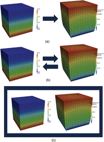
These three options are depicted in . The top coupling represents a one-way loose coupling where, in each time step, one physics is solved and the solution is passed to the next physics solver. The other physics is then solved, and time marches forward. The second coupling utilizes Picard iteration to converge the two physics within each time step. The final coupling method, the one originally utilized by MOOSE, is full coupling: All PDEs within the system are solved simultaneously, resulting in a completely converged solution within one solve. While a fully coupled simulation has many advantages when physics are interdependent, it can be overly burdensome for loosely coupled physical systems. Therefore, utilization of the MultiApp and transfer systems for loose coupling and Picard iteration can be useful for multiscale solves, solves involving multiple timescales, and solves utilizing external applications. The Cardinal application developed for lower-length-scale simulation of FHRs utilizes MultiApp for just this purpose: coupling Nek5000, OpenMC, and BISON.
Fig. 4. MOOSE coupling strategies: (a) loose, (b) Picard, and (c) full
II.B. Design of Cardinal
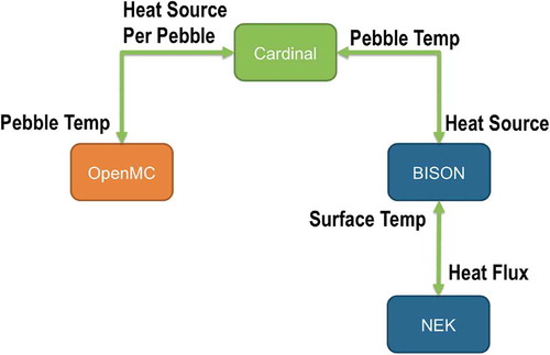
Cardinal utilizes the MOOSE MultiApp capability to place each of the applications to be coupled within a hierarchical tree-based structure, as shown in . This structure was chosen based on how tightly coupled the physics are. BISON and Nek5000 form one branch because of the instantaneous feedback between the CHT and the pebble temperature. The Nek5000 solution provides the temperature boundary condition on each pebble exterior, while BISON returns the heat flux at each point around the pebble to Nek5000. Another benefit of having BISON and Nek5000 on their own branch is the way it impacts time stepping. Within the MultiApp setup shown in , the branch containing BISON and Nek5000 can take many small time steps and even iterate between BISON and Nek5000 within a time step without needing to re-solve OpenMC. This can significantly reduce the time to solution of the application. OpenMC is then separate from the other two. It receives fuel/pebble temperatures from BISON and returns a heat source that is transferred down to BISON. OpenMC is currently solving for steady-state neutronics and can take larger time steps compared with BISON and Nek5000 (which are both performing transient heat conduction and CFD solves, respectively). The flexibility of the MOOSE MultiApp system allows for just such a setup.
Fig. 5. Diagram showing the design of Cardinal
II.B.1. Build System
In any multiphysics coupling project with many dependent libraries, ensuring consistent compilation and linking can be a challenge. Throughout Cardinal, we rely on PETSc to detect system-dependent configuration information and install as many third-party libraries as possible (). BISON, MOOSE, and libMesh already rely on PETSc, and they are built as usual. For standalone OpenMC and Nek5000, PETSc is not a dependency; but in Cardinal, OpenMC and Nek5000 use PETSc for two purposes:
PETSc is built on top of HDF5 and BLAS/LAPACK, which are also dependencies of OpenMC and Nek5000, respectively.
The configuration information discovered by PETSc is passed to the build systems of OpenMC and Nek5000.
Fig. 6. Diagram describing the build system of Cardinal
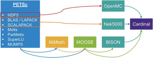
This is done through header files that PETSc generates specifically for this purpose. Hence, after installing PETSc and libMesh, Cardinal can be built in one step. The build system also allows Cardinal to run on the Summit supercomputer at Oak Ridge National Laboratory (ORNL).
II.B.2. Nek5000/NekRS and API
Nek5000 (CitationRefs. 21 and Citation22) is an open-source simulation software package that delivers highly accurate solutions for a wide range of scientific applications, including fluid flow, thermal convection, combustion, and magnetohydrodynamics. It features state-of-the-art, scalable, high-order algorithms that are fast and efficient on platforms ranging from laptops to the DOE leadership computing facilities.
Nek5000 is based on the spectral element methodCitation23 in which the domain is decomposed globally into smaller domains (elements) that are assumed to be curvilinear hexahedra (brick meshes) conforming to the domain boundaries. Locally, functions within each element are expanded in tensor-products of high-order (typically to 12) polynomials. The pressure can be solved at the same polynomial order as the velocity
(
formulation) or at lower order
(
formulation). Temporal discretization is based on a high-order splitting that is third-order accurate in time and reduces the coupled velocity-pressure Stokes problem to four independent solves per time step: one for each velocity component and one for the pressure. The velocity problems are diagonally dominant and thus easily solved by using Jacobi preconditioned conjugate gradient iteration. Two time-stepping schemes, both up to third order, are available: semi-implicit backward differentiation formula extrapolation or subcycle-based characteristics. The characteristics scheme permits relatively large time steps corresponding to Courant-Friedrichs-Lewy (CFL) numbers of 4 or more.Citation24 The pressure substep requires a Poisson solve at each step, performed through the multigrid-preconditioned generalized minimal residual method iteration coupled with temporal projection to find an optimal initial guess. Particularly important components of Nek5000 are its scalable coarse-grid solvers that are central to parallel performance. For both weak and strong scaling, using algebraic multigrid for the coarse-grid solve is essential above 250 000 elements. Nek5000 employs a pure message passing interface (MPI) parallel implementation. An extensive discussion of the scalability of Nek5000 is provided in CitationRefs. 25 and Citation26.
We note that Nek5000 relies on hexahedral conformal meshes, which are generally more challenging to construct than meshes with tetrahedral elements. We have developed a tetrahedral-to-hexahedral (tet-to-hex) technique that enables the use of Nek5000 on complex geometries and that produces remarkably well-conditioned meshes.Citation27 Our early trials for the pebble bed are based on this approach. To scale to very large pebble counts, however, we are developing a tailored approach to the generation of all-hexahedral meshes in the pebble void regions that is based on a tessellation of the Voronoi cells defined by the pebble centers. The Voronoi cells are generated using MATLAB or other off-the-shelf software. In the domain interior, each facet is associated with two spheres. The facet is tessellated into a few quadrilaterals, the images of which are then projected onto the spheres resulting in a valid-baseline all-hexahedral mesh. Facets on the domain boundary are generated by having image elements reflected through the boundary to the domain exterior. These are similarly partitioned and projected onto the single interior sphere that they face. The elements swept out by the projection process are partitioned radially (typically into three elements in the radial direction), and the overall mesh is smoothed using the algorithms presented in CitationRef. 28. Refinements of the algorithm include deletion (collapse) of short edges in the Voronoi cells and insertion of points on long edges in order to produce a more uniform mesh throughout the domain. The Voronoi-based approach leads to a sixfold reduction in element count (thus enabling the use of higher polynomial order) and significant reduction in the CFL for a given time-step size compared to the more general tet-to-hex strategy. We demonstrate the results for this approach for pebble-bed examples in Sec. IV.
Nek5000 couples to MOOSE in a simple way:
A point cloud with the Gauss-Lobatto-Legendre points corresponding to the surface mesh (corresponding to either
or
A set of routines is then defined for solution transfer. The temperature is extracted on the Nek5000 mesh and loaded onto the points cloud in MOOSE.
The flux data are loaded from the points cloud and used to reconstruct an arbitrary order-N surface field for the heat flux.
A set of routines for time stepping is defined.
We note that even with a relatively large problem like the demonstration problem discussed in this paper, the solution transfer’s memory footprint and computational cost are not significant compared with the physics solves.
Cardinal also interfaces with NekRS, a new GPU-oriented version of Nek5000 that is also capable of running on CPUs. It represents a significant redesign of the code. While written in C++, NekRS is able to link to Nek5000 to leverage its extensive pre- and post-processing utilities. NekRS has been built primarily under the auspices of the DOE’s Exascale Computing Project. It realizes high throughput on advanced GPU nodes and demonstrates excellent scalability. Details of NekRS performance for nuclear applications have been provided in recent publications.Citation29 The Cardinal API of NekRS heavily uses the Cardinal API of Nek5000 and yields identical results.
All pebble-bed simulations performed here use either LES, using an explicit filter,Citation30 or DNS. The CFD resolution requirements are thus significant, about 150 000 points per pebble. The rapid convergence of the high-order discretizations in Nek5000 and NekRS and their high performance on the DOE’s leadership computing facilities makes them ideally suited for this set of simulations.
II.B.3. OpenMC and API
OpenMC (CitationRef. 31) is a general-purpose Monte Carlo particle transport simulation code focused on coupled neutron-photon calculations. It is capable of simulating 3-D models based on constructive solid geometry (CSG) with second-order surfaces or computer-aided-design geometries. OpenMC supports either continuous-energy or multigroup transport. The continuous-energy particle interaction data are based on a native HDF5 format that can be generated from ACE files used by the MCNP and Serpent Monte Carlo codes. Additionally, OpenMC can use multipole cross-section data for temperature feedback calculations (as in Cardinal).
For Cardinal, we use the C/C++ API of OpenMC to start and stop the simulation at various levels (including the overall simulation and individual batches) and for accessing underlying data structures (such as cell, material, and tally data) during online coupling.
Like several other Monte Carlo transport simulators (such as MCNP), OpenMC uses CSG to build models in Euclidean space. Volumes, also referred to as cells, are bounded by quadratic surfaces that are defined by parameterized equations, not grid points. A given surface defines a positive and negative half-space, and Boolean combinations (intersections, unions, and differences) of these half-spaces can form arbitrarily complex volumes. Moreover, in OpenMC, each cell contains one or more materials; each material in turn contains information about nuclide identities, nuclide atom densities, and overall material density. Each cell also contains temperature information; note that temperature information is not associated with the material. Instead, temperature information is associated with cells to provide a spatial distribution of this property.
Previous efforts have attempted to couple OpenMC to MOOSE for LWR applications.Citation32 However, the current effort takes a new approach. In particular, we have implemented two options:
Cell-based API: We leverage MWA features to develop a specialized interface for the pebble-bed reactor problem. To transfer temperature from BISON to OpenMC, we must update the temperature of an OpenMC cell, which updates the temperature of each material in the cell. Heat sources are also tallied on each pebble and transferred to BISON.
Mesh-tally API: In the following, we discuss in more detail the mesh-tally API. In order to capture heat generation in the OpenMC simulation, a tally scoring total recoverable fission energy per source particle is applied to each pebble’s outer cell in the bed. These tallies are created at runtime during the problem setup by using a list of pebble centers to locate the uppermost cell in the CSG geometry hierarchy containing that point.
As summarized in EquationEq. (1(1)
(1) ), the energy deposition for each pebble
is normalized by the total energy deposition in the bed:
This value is then multiplied by the total thermal power of the reactor to obtain an average heat generation rate for each pebble
and divided by the volume of each pebble
to obtain a volumetric heat generation rate
. This results in a single average heating value for the entire pebble. Before being transferred to the MOOSE mesh, these values are normalized by the total heat.
For improved spatial resolution of heat generation in the pebble bed, unstructured mesh tallies have been implemented in OpenMC. provides an example of this capability applied to a single pebble. The unstructured mesh representation relies on a libMesh mesh instance and currently conforms to the OpenMC tally data model that separates the mesh structure from the tally data. The separation of this information allows the unstructured mesh to be applied in a mesh filter object that is agnostic to the underlying mesh type. The mesh filter can then be combined with other specified filters, scores, and nuclides in a tally and can be used in one or more tally definitions. Calls into the libMesh library from OpenMC are agnostic to the type of elements used, so meshes can be formed by using any element type supported by libMesh.
Fig. 7. Qualitative view of a heating tally on an unstructured mesh: (a) cut-away of the pebble geometry as represented in OpenMC and (b) result of an applied heating tally where heating occurs only in the region of the pebble containing TRISO particles
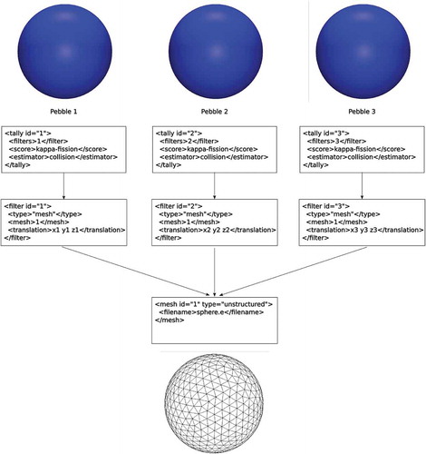
A mesh for each pebble is applied in the Cardinal problem to capture the heat generation distribution throughout the pebble bed. In order to avoid replicating a mesh representing all of the pebbles from either MOOSE or NekRS, the addition of translations to mesh filters was introduced in OpenMC. Placing the translation at this layer of the tally model allows all tallies to rely on a single libMesh mesh instance acting as a template to represent any pebble in the bed, as shown in . This results in a minimal memory footprint even when tallying energy deposition for an entire pebble bed. The translation values for each mesh filter are set using the list of pebble centers provided in the MOOSE input file. During problem initialization, these translations are used to calculate the location of element centers in the MOOSE mesh when transferring heat-generation values to MOOSE.
Fig. 8. Organization of unstructured mesh tallies for heat generation in OpenMC
Temperature values from MOOSE are updated in OpenMC by using an average temperature value at the pebble center. An option has been added in OpenMC to automatically update the temperature value of all cells inside a pebble to simplify this process.
II.B.4. BISON
BISON is a MOOSE-basedCitation15,Citation33 nuclear fuel simulation tool developed primarily at Idaho National Laboratory (INL). BISON is capable of performing high-fidelity finite-element simulation of various fuel forms, including LWR fuel rods, TRISO fuel particles, and plate fuel. MOOSE allows BISON to solve many coupled physics, including heat conduction, solid mechanics, burnup, material evolution, plasticity, creep, fracture, fission gas buildup, gap heat conduction, and neutron embrittlement. In addition, BISON uses MOOSE to perform these coupled simulations within an implicit solution scheme allowing for the long time steps and high-order time integration necessary for the simulation of operating reactors.
BISON is a high-fidelity tool that has been developed to achieve predictive capability. It has undergone rigorous assessment testing and verification analysis to ensure accurate simulation. Further, BISON is developed by using a rigorous verification and validation (V&V) plan. We note that since BISON is a native MOOSE-based application, there is no need for an API. We note also that calculations performed in this paper exercise only the conduction module, without any sophisticated fuel performance modeling as an initial demonstration step.
III. VERIFICATION AND VALIDATION
In this section we describe the V&V steps for the coupled pebble-bed simulations. We remark that all of the constituent codes have an extensive verification history for standalone and multiphysics applications.
III.A. Flow and Heat Transfer V&V
III.A.1. Nek5000: Canonical Cases
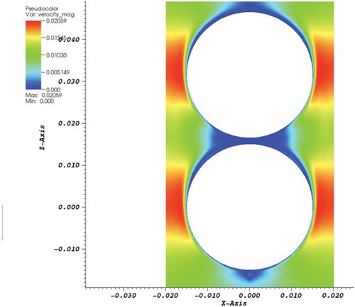
To verify the fluid-flow model and the solution transfer, we have devised two cases: a single-pebble and a two-pebble case. The Nek5000-MOOSE coupling was verified to yield the same results as standalone Nek5000 CHT results. We note that work in Cardinal was based on previous work conducted on Nek5000-MOOSE coupling.Citation34 Single-pebble () and two-pebble () cases were used to verify the solution transfer. They were also used to verify the coupling with OpenMC and BISON. For instance, the neutronics results showed a clear bias between pebbles and a tilt induced by the temperature gradient.
Fig. 9. Verification test for single pebble and comparison with experiment: (a) simulation results, (b) mesh, and (c) comparison with experiment.Citation44–46
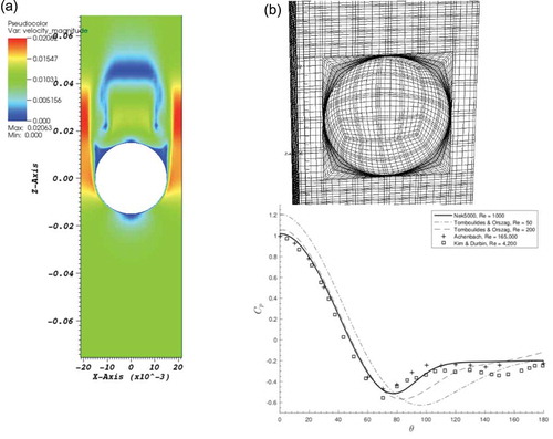
Fig. 10. Verification test for two-pebble simulation (velocity magnitude)
Selected results from the single-pebble case were also compared with results from experimental and computational studies carried out using a similar geometry (). A well-quantified quantity for flow over a single sphere is the averaged streamwise velocity along the domain axial centerline. compares our result with completed numerical results. shows the profile generated from DNS data in CitationRef. 35 at Re = 3700 and shows the downstream location () and magnitude of the maximum recirculation (i.e., negative streamwise) velocity for LES and detached eddy simulation data generated at Re = 10 000. One can see that for increasing Reynolds number, the magnitude of the recirculation velocity increases, while the downstream distance from the sphere where this maximum occurs decreases. We do not quantify this trend’s specific dependence on the Reynolds number here, but our result is consistent with the literature.Well-quantified quantities for the flow over a single sphere are the averaged streamwise velocity along the domain axial centerline and the azimuthal distribution of the pressure coefficient. compares our result with completed numerical results for the latter. In CitationRef. 35 one can find more detailed comparisons for the streamwise velocity data. We do not discuss this quantitatively here, but our result is consistent with the literature.
III.A.2. NekRS-BISON Coupling
We have also directly compared results obtained with the NekRS version of Cardinal versus Nek5000. The case setup is identical to the one used for the verification of the MOOSE-Nek5000 coupling. Some results for the temperature distribution are shown in .
Fig. 11. Verification test for single-pebble result: (a) 3-D temperature distribution in the whole domain and (b) cross section at y = 0.016 m
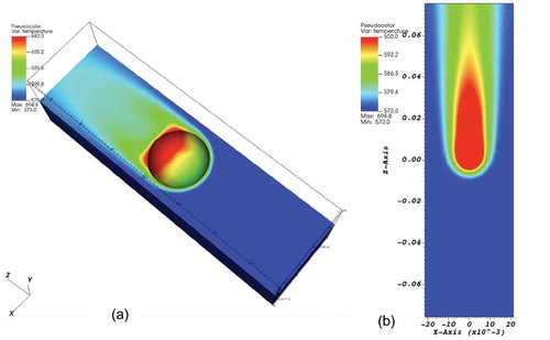
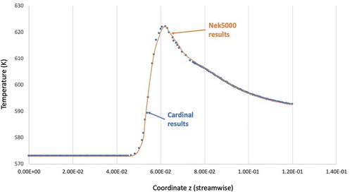
presents single-pebble results in Cardinal where the fluid is simulated in NekRS and the interior of the pebble is simulated with BISON (in this case with the heat conduction module of MOOSE). The results are compared with solutions obtained with Nek5000 standalone using the CHT feature of the code. Temperature profiles are compared on a line at y = 0.016 m and x = 0 m while the domain is centered at the pebble center, and the pebble diameter is D = 0.03 m. We note that the results are nearly identical if a quadratic representation of the surface is employed.
Fig. 12. Verification test for single-pebble comparison with standalone Nek5000 results
III.A.3. Pebble Beds
Over the past several years, NEAMS has dedicated several efforts to the modeling and simulation of the detailed flow in a pebble bed. For instance, Fick et al.Citation36 performed a complete DNS of pebble-bed flow. Complete statistical data were obtained from this DNS study, with an investigation of low-frequency temporal instabilities. However, Fick et al.’s studyCitation36 used a structured pebble bed, which limits its application. Nonetheless, it was compared against other available DNS data and proved that Nek5000 can deliver high-quality simulation data for pebble beds.
A more recent study was aimed at simulating the flow in a random pebble bed.Citation37 This random pebble-bed geometry was obtained from an experiment conducted by Nguyen et al.Citation38 The experiment measured detailed velocity distributions using particle image velocimetry (PIV) and matched index of refraction within a pebble bed. A DNS of the flow field was then conducted for a short section of the bed comprising 147 pebbles, corresponding to the test section and additional layers of pebbles. The pebble locations were obtained from the experimental facility by using a combination of PIV and image recognition algorithms.
To create a pure hexahedral mesh for a random pebble bed is challenging using the traditional blocking method. With the tet-to-hex meshing method, however, we created a pure hexahedral mesh for this geometry. In order to reduce the total element count, chamfers were created at pebble-pebble interfaces. As discussed, the computational domain is only a small section of the whole experimental domain; therefore, we applied periodic boundary conditions at the inlet/outlet to mimic the upstream/downstream.
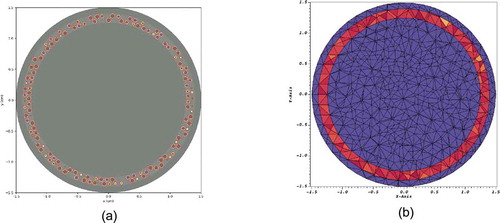
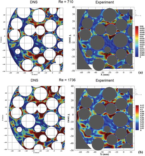
shows selected results of velocity field in the random pebble bed. The flow field is complex because of the randomly distributed pebbles. Note that some pebbles may appear smaller, but this is an effect of the plane cutting through the bed. shows a comparison of experimental and simulation results at two flow Reynolds numbers. Despite the complexity of the geometry, the computational results compared favorably. A more in-depth analysis of the results is provided in CitationRef. 37.
Fig. 13. Simulation results for the TAMU experiment, velocity magnitude: (a) cross section at y = 1.0 and (b) 3-D contour plot
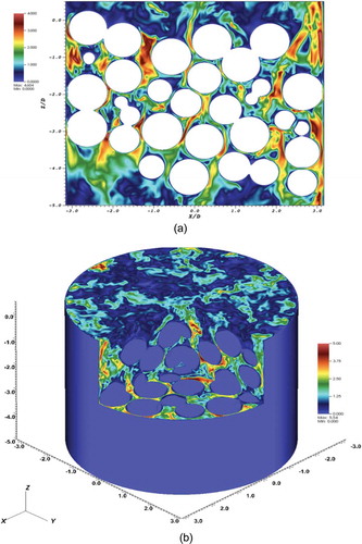
Fig. 14. TAMU experiment: comparison of simulation with experiment in a plan normal to the streamwise direction at two Reynolds numbers
III.B. Neutronics V&V
We considered a pebble-bed configuration similar to the pebble experiment in . We compared results from OpenMC with results obtained with MCNP.
For this demonstration, the sizes and composition of the TRISO particles were based on TRISO manufactured by Phillips et al. at INL (CitationRef. 39). Although these particles were developed for the advanced gas-cooled reactor (AGR) fuel, particles with the same specifications are used for FHR test reactors and computations benchmarks.Citation40 The pebbles’ sizes and compositions were taken from the Mark 1 FHR reactor constructed at the University of California-Berkeley.Citation40 , , , and show these specifications.
TABLE I TRISO Composition
TABLE II Pebble Composition
TABLE III Coolant Composition
TABLE IV TRISO and Pebble Dimensions
The resultant OpenMC model is shown in . In this exercise, the TRISO particles were packed in a regular square lattice with the same overall packing fraction described by CitationRef. 39 rather than a randomized and/or irregular distribution. This choice was made to simplify the direct code-to-code comparison. Some optimization methods specifically for the generation of randomly distributed TRISO particles are available in OpenMC (CitationRef. 41) and can be optionally applied in the Cardinal demonstration simulations discussed here.
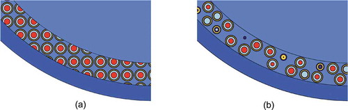
Fig. 15. Two-dimensional slices of the OpenMC model of an FHR pebble with both (a) regular and (b) random distributions. Red represents fuel, yellow represents SiC, and blue represents graphite (where darker shades are more dense)
presents comparisons for the k-eigenvalue computed with OpenMC and MCNP for various boundary condition combinations. We note the strong sensitivity to the radial boundary condition, given the small size of the domain. Overall the results are consistent between the two codes.
TABLE V Eigenvalue for OpenMC and MCNP Calculations
IV. DEMONSTRATION SIMULATIONS
We demonstrate here the use of Cardinal on two pebble-bed configurations that are representative of FHR cores. The first case consists of 146 pebbles and it is run with Nek5000 on CPUs. The second consists of 1568 pebbles and it is performed with NekRS running on GPUs.
IV.A. 146 Pebbles
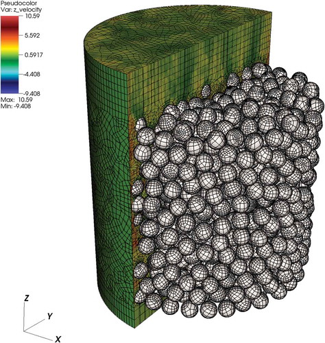
Using the Nek5000 model of the Texas A&M University (TAMU) experiment as a basis, we have developed a multiphysics simulation of a bed comprising 146 pebbles. The pebble model for Nek5000 reflects the practices used for the TAMU experiment, which were validated carefully against experimental PIV data. Inlet/outlet boundary conditions are used (). We assume constant properties.
Fig. 16. Mesh and boundary conditions for Nek5000 problem (146 pebbles)
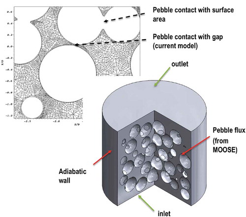
The mesh was constructed using the tet-to-hex approach and comprises approximately 500 000 elements overall. It is designed to run at for coarse results and
for finer simulations (for a maximum of 256 million grid points). The mesh is also designed to allow for a small clearance between pebbles equal to 1% of the pebble diameter. This design facilitates the demonstration simulation, but it will likely be updated in future simulations with more realistic contact models. We note that the mesh for the TAMU experiment simulations discussed in Sec. III assumes area contact between pebbles, and no significant differences in the flow field between the two approaches were observed. The difference between the two meshes is outlined in .
We note that this small-size bed is not representative of the behavior of large pebble beds, but it was chosen because of the availability an experimental data set for comparison (at least for the thermal-hydraulic model). It should be seen only as an initial demonstration step, in an effort to scale to larger pebble beds.
To test various options and accelerate development, we defined four variants of the demonstration problem, all available in the Cardinal repository. The variants reflect the need to define cheaper transients for testing purposes. shows the cases; they are listed in order of increasing computational cost. Restarting from an advanced restart leads to faster convergence. Moreover, simulating the full Navier-Stokes is considerably more expensive than assuming a “frozen velocity” and solving only the advection-diffusion equation.
TABLE VI Nek5000 Cases with Various Solver Options
The OpenMC model is consistent with the pebble-bed model discussed in Sec. III.B. For BISON and the demonstration problem, we consider only the conduction equation, and hence it is a relatively straightforward setup. Properties are constant and adapted from available correlations. The mesh for a single sphere is generated and replicated at runtime. Only cell-based tallies were considered for this demonstration.
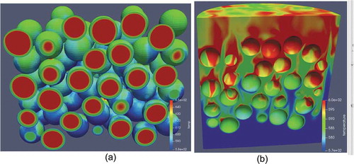
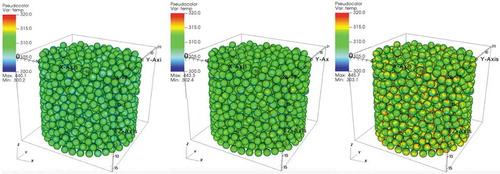
For the coupled simulations, we opted to tightly couple Nek5000 and BISON and loosely couple OpenMC, given that if OpenMC is executed at every step, the computational cost becomes excessive. We performed the OpenMC solve every 100 steps. The simulations were performed on 2000 processors. Snapshots of the state after an initial transient are shown in and . In particular, we observed the following:
the effect of the complex flow field on the surface temperature of the pebbles
a slight tilt in the temperature distribution in the fuel’s interior due to the outer temperature condition of each pebble
the effect of the reflective boundary conditions on the power distribution and a slight power tilt toward the bottom of the bed due to the colder coolant.
Fig. 17. TAMU demonstration results: snapshots of (a) temperature on surface, (b) average temperature in solid, and (c) average heating
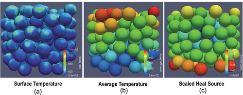
Fig. 18. TAMU demonstration results: (a) temperature in the solid and (b) temperature details in the fluid
IV.B. 1568 Pebbles
IV.B.1. Numerical Setup
We also present a case comprising 1568 pebbles. The pebble configuration was obtained by using a discrete element method code.Citation42 The mesh has 524 000 elements and was generated using the Voronoi cell strategy described in Sec. II.B.2. The configuration is illustrated in . Meshes for higher pebble counts exhibit similar element-to-pebble ratios. We note that 1568 pebbles is a significant size for a coupled calculation and is representative of the SANA experiments,Citation43 for instance.
Fig. 19. NekRS: A spectral element mesh using 524 386 spectral elements for the 1568-pebble configuration. The mesh is generated by an all-hexahedral meshing tool based on Voronoi cell strategy
For this demonstration, the sizes and composition of the TRISO particles were based on those manufactured at INL, following the practice established in Sec. III.A. Although these particles were developed for the AGR fuel, particles with the same specifications are used for FHR test reactors and computation benchmarks. The sizes and compositions of the pebbles were taken from the Mark 1 FHR reactor design. For BISON and the demonstration problem, we consider only the conduction equation, and hence it is a relatively straightforward setup. Properties are constant and adapted from available correlations. The mesh for a single sphere is generated and replicated at runtime. The same mesh is used for the mesh tallies in OpenMC.
IV.B.2. Results
We begin by demonstrating the strong scaling performance of NekRS (GPU) and NekRS (CPU) in . We measured timings for 100 time steps for turbulent flow simulations with the 1568-pebble mesh on ORNL’s Summit, using 42 MPI ranks per node for the CPU runs and 6 Nvidia V100s per node for the GPU runs. For the same node count, the GPU-accelerated variant of NekRS is more than 9× faster when using 3.5 million points per GPU (here, 7283 spectral elements per GPU and ). The total number of grid points is n = 179 864 398 (E = 524 386and N = 7). The NekRS GPU run realizes 82% parallel efficiency at 2.1 million points per GPU.
TABLE VII NekRS GPU/CPU Strong Scale Timings for 1568-Pebble Case
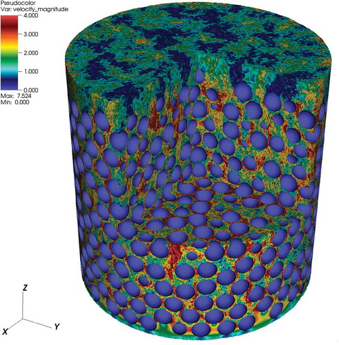
For the coupled-physics demonstration, the 1568 model described in Sec. IV.B.1 has been run on up to 20 nodes of Summit, with six MPI ranks on each node corresponding to the six GPUs on each node. The OpenMC and BISON models are designed to run on CPUs, while the NekRS model runs on the GPU. Prior to coupling, NekRS was used to run a standalone LES out to 25 convective time units in order to develop and generate a turbulent initial condition, which is shown in .
Fig. 20. NekRS: A velocity component for turbulent flow simulations using the spectral element mesh with 524 386 spectral elements for 1568 pebbles from the all-hexahedral meshing tool based on Voronoi cell strategy
The flow initial condition was used to restart a coupled transient simulation in Cardinal representing the pebbles’ heat up. The time step was fixed to s in both BISON and NekRS. The temperature at time zero was set to 300◦C everywhere. presents the temperature at the surface of the pebbles in BISON at three points in time. The simulations took 2.5 s per coupled time step on 20 nodes, requiring transfer between physics at each time step. However, this time could be significantly optimized by relaxing the requirement, since data transfer from GPU to CPU should be minimized as much as possible.
Fig. 21. Temperature result for the pebble surface temperature at three points in time
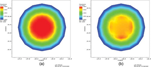
The results of the OpenMC simulations coupled with the heat conduction module are shown in and with the same time-step parameters as the NekRS simulations described earlier. An eigenvalue simulation using 150 batches with 50 inactive batches was executed in each time step. Fifty-thousand particles per batch were used to converge the pebble-averaged heat source from the OpenMC cell tally, while the unstructured mesh heat source tally required 500 000 particles per batch to produce the heat source presented here. Production simulations may require an even higher number of particles per batch to more tightly converge the heating distribution when using the unstructured mesh heat source due to the decreased number of samples per source particle in the smaller tally bins. demonstrates the effect of the improved spatial resolution provided by the unstructured mesh heat source from OpenMC on the temperature distribution within a representative pebble. In the case of the pebble-averaged heat source, the temperature profile is symmetric, reflecting the uniform heat source applied in that region. In contrast, a clear asymmetry can be seen in the profile generated from the unstructured mesh heat source indicating that the improved spatial resolution of the heat source has an impact on the temperature distribution in the solid and will in turn affect the resulting heat transfer to the fluid. We emphasize that the results presented in this section are for demonstration purposes and additional investigation is needed.
Fig. 22. (a) Heat source using the original cell tallies to produces an average heat source per pebble and (b) heat source produced using an OpenMC unstructured mesh tally
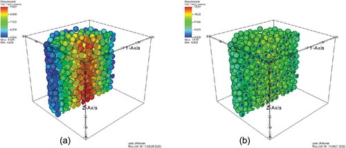
Fig. 23. (a) Temperature in the solid resulting from the cell-based heating tally and (b) temperature in the solid resulting from the unstructured mesh heating tally in OpenMC
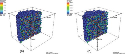
Fig. 24. Temperature profiles of the same pebble in the 1568-pebble demonstration using (a) pebble-averaged heating and (b) unstructured mesh heating
IV.C. Projection to Full Core
Twenty nodes represent less than 1% of the computing power available on Summit, which is sufficient for 1568 pebbles at 2.1 million points per GPU. Performance throughput for NekRS saturates at 2 to 4 million points per GPU on Summit. By running with 4 million points per GPU, we estimate that 80% of the machine will be sufficient to perform a full-core calculation in FHRs corresponding to 300 000 pebbles.
We note that in addition to the cases presented here, additional NekRS cases have been meshed and simulations performed on Summit. In fact demonstrates our current all-hexahedral meshing capability based on Voronoi cell strategy up to 11 145 pebbles using 3.5 million spectral elements (total 2 billion grid points, ) and their averaged wall time per time step from flow simulations with Re = 5000 between 14 000 to 15 750 time steps.
TABLE VIII NekRS Simulation Timings on GPU with All-Hexahedral Meshes for Pebble Beds*
V. CONCLUSIONS AND FUTURE WORK
In this paper, we described the creation of Cardinal, which provides a platform for running coupled OpenMC-Nek5000/NekRS-BISON simulations. We demonstrated Cardinal’s application to FHR demonstration problems and presented a limited V&V case. This exercise demonstrates that the MWA paradigm works well. Moreover, by wrapping OpenMC and Nek5000, they can now be coupled to any other MOOSE-based application.
We demonstrated the application of Cardinal with a first-of-a-kind simulation on Summit, representing a pebble count increase compared with previous LES simulations. This exercise demonstrates that the MWA paradigm works well, even on a GPU platform such as Summit. In these simulations, OpenMC and BISON run on CPUs while NekRS runs on GPUs. The current results provide a clear pathway toward full-core simulations.
Future work on Cardinal will involve a more sophisticated thermal contact treatment between pebbles, leveraging novel ideas using MOOSE constraints. We may also explore more advanced solution transfer mechanisms such as functional expansion tally transfers to and from OpenMC and Nek5000. We will also work on improving the scalability of transfers. We aim to achieve massively parallel simulations going up to the entire Summit machine for full-core simulations. These simulations may involve asynchronous parallel execution between the physics. In these simulations, a multiscale approach may also be employed to simulate a select number of fuel particles directly.
Extension to gas reactor pebble beds will also be considered. As part of this effort, a radiative heat transfer model will be added to Cardinal because this is an important component of the overall heat transfer behavior.
Acknowledgments
Argonne National Laboratory’s work was supported by the DOE’s NE’s NEAMS and Office of Science under contract DE-AC02-06CH11357 and the Exascale Computing Project (17-SC-20-SC). This research used resources of the Oak Ridge Leadership Computing Facility at Oak Ridge National Laboratory, which is supported by the Office of Science of the U.S. Department of Energy under Contract No. DE-AC05-00OR22725.
References
- D. SHAVER et al., “Initial Industry Collaborations of the Center of Excellence,” ANL/NSE-19/15, Argonne National Laboratory (2019).
- M. R. TONKS et al., “Multiscale Development of a Fission Gas Thermal Conductivity Model: Coupling Atomic, Meso and Continuum Level Simulations,” J. Nucl. Mater., 440, 1–3, 193 (2013); https://doi.org/10.1016/j.jnucmat.2013.05.008.
- C. FORSBERG et al., Fluoride-Salt-Cooled High-Temperature Reactor (FHR) for Power and Process Heat, Massachusetts Inst. of Technology (2015).
- A. CHARALAMPOS et al., “Technical Description of the ‘Mark 1’ Pebble-Bed Fluoride-Salt-Cooled High-Temperature Reactor (PB-FHR) Power Plant,” Technical Report, Department of Nuclear Engineering, University of California-Berkeley (2014).
- J. CLEVELAND and S. R. GREENE, “Application of THERMIX-KONVEK Code to Accident Analyses of Modular Pebble Bed High Temperature Reactors (HTRs), Oak Ridge National Laboratory (1986).
- V. SEKER and T. DOWNAR, “Multiphysics Methods Development for High Temperature Gas Cooled Reactor Analysis,” Proc. Int. Conf. Emerging Nuclear Energy Systems (ICENES), p. 3, Istanbul, Turkey, June 3–8, 2007.
- A. J. NOVAK et al., “Pronghorn Theory Manual,” Idaho National Laboratory (2018).
- A. NOVAK et al., “Pronghorn: A Multidimensional Coarse Mesh Application for Advanced Reactor Thermal-Hydraulics,” Nucl. Technol., 207, 1015 (2021); https://doi.org/10.1080/00295450.2020.1825307.
- A. NOVAK et al., “Multiscale Thermal-Hydraulic Methods for Salt-Cooled Pebble Bed Reactors,” Ann. Nucl. Energy, 154, 107968 (2021); https://doi.org/10.1016/j.anucene.2020.107968.
- M. van STADEN, B. NEYKOV, and E. MULDER, “Explicit Modelling of Randomly Packed Pebble Bed Using RANS CFD Modelling,” Proc. HTR-2018, Warsaw, Poland, October 8–10, 2018.
- R. HU, “SAM Theory Manual,” ANL/NE-17/4, Argonne National Laboratory (2017).
- Y. WANG et al., “Rattlesnake: A MOOSE-Based Multiphysics Multi-Scheme Radiation Transport Application,” Nucl. Technol., 207, 1047 (2021); https://doi.org/10.1080/00295450.2020.1843348.
- P. K. ROMANO and B. FORGET, “The OpenMC Monte Carlo Particle Transport Code,” Ann. Nucl. Energy, 51, 274 (2013); https://doi.org/10.1016/j.anucene.2012.06.040.
- P. FISCHER et al., “Petascale Algorithms for Reactor Hydrodynamics,” J. Phys. Conf. Ser., 125, 1, 012076 (2008); https://doi.org/10.1088/1742-6596/125/1/012076.
- J. HALES et al., “Multidimensional Multiphysics Simulation of TRISO Particle Fuel,” J. Nucl. Mater., 443, 1–3, 531 (2013); https://doi.org/10.1016/j.jnucmat.2013.07.070.
- D. GASTON et al., “MOOSE: A Parallel Computational Framework for Coupled Systems of Nonlinear Equations,” Nucl. Eng. Des., 239, 10, 1768 (2009); https://doi.org/10.1016/j.nucengdes.2009.05.021.
- C. J. PERMANN et al., “MOOSE: Enabling Massively Parallel Multiphysics Simulation,” SoftwareX, 11, 100430 (2020); https://doi.org/10.1016/j.softx.2020.100430.
- D. R. GASTON et al., “Physics-Based Multiscale Coupling for Full Core Nuclear Reactor Simulation,” Ann. Nucl. Energy, 84, 45 (2015); https://doi.org/10.1016/j.anucene.2014.09.060.
- E. MERZARI et al., “Cardinal: A Lower Length-Scale Simulator for Fluoride Cooled High Temperature Reactors,” ANL/MCS-TM-383, Argonne National Laboratory (2019).
- B. S. KIRK et al., “libMesh: A C++ Library for Parallel Adaptive Mesh Refinement/Coarsening Simulations,” Eng. Comput., 22, 3–4, 237 (2006); https://doi.org/10.1007/s00366-006-0049-3.
- P. FISCHER et al., “Nek5000: Users Manual,” Technical Report ANL/MCS-TM-351, Argonne National Laboratory (2015).
- “Nek5000,” Nek5000 Contributors (2020); https://github.com/Nek5000/Nek5000 (current as of July 14, 2020).
- A. PATERA, “A Spectral Element Method for Fluid Dynamics: Laminar Flow in a Channel Expansion,” J. Comput. Phys., 54, 3, 468 (1984); https://doi.org/10.1016/0021-9991(84)90128-1.
- S. PATEL et al., “A Characteristic-Based, Spectral Element Method for Moving-Domain Problems,” J. Sci. Comp, 79, 1, 564 (2019); https://doi.org/10.1007/s10915-018-0876-6.
- P. FISCHER, K. HEISEY, and M. MIN, “Scaling Limits for PDE-Based Simulation (Invited),” Proc. 22nd AIAA Computational Fluid Dynamics Conf., AIAA Aviation, AIAA, Dallas, Texas, June 22–26, 2015.
- P. FISCHER et al., “Scalability of High-Performance PDE Solvers,” Int. J. High Perform. Comput. Appl., 34, 562 (2020); https://doi.org/10.1177%2F1094342020915762.
- H. YUAN et al., “Spectral Element Applications in Complex Nuclear Reactor Geometries: Tet-to-Hex Meshing,” Nucl. Eng. Des., 357, 110422 (2020); https://doi.org/10.1016/j.nucengdes.2019.110422.
- K. MITTAL and P. FISCHER, “Mesh Smoothing for the Spectral Element Method,” J. Sci. Comp., 78, 2, 1152 (2019); https://doi.org/10.1007/s10915-018-0812-9.
- E. MERZARI et al., “Toward Exascale: Overview of Large Eddy Simulations and Direct Numerical Simulations of Nuclear Reactor Flows with the Spectral Element Method in Nek5000,” Nucl. Technol., 206, 1308 (2020); https://doi.org/10.1080/00295450.2020.1748557.
- P. FISCHER and J. MULLEN, “Filter-Based Stabilization of Spectral Element Methods,” Comptes Rendus de l’Académie des Sciences-Ser. I-Math., 332, 3, 265 (2001); https://doi.org/10.1016/S0764-4442(00)01763-8.
- P. K. ROMANO et al., “OpenMC: A State-of-the-Art Monte Carlo Code for Research and Development,” Ann. Nucl. Energy, 82, 90 (2015); https://doi.org/10.1016/j.anucene.2014.07.048.
- M. ELLIS et al., “Preliminary Coupling of the Monte Carlo Code OpenMC and the Multiphysics Object-Oriented Simulation Environment for Analyzing Doppler Feedback in Monte Carlo Simulations,” Nucl. Sci. Eng., 185, 1, 184 (2017); https://doi.org/10.13182/NSE16-26.
- R. L. WILLIAMSON et al., “Multidimensional Multiphysics Simulation of Nuclear Fuel Behavior,” J. Nucl. Mater., 423, 1–3, 149 (2012); https://doi.org/10.1016/j.jnucmat.2012.01.012.
- A. NOVAK et al., “Preliminary Coupling of OpenMC and Nek5000 Within the MOOSE Framework,” Proc. PHYSOR, Cancun, Mexico, April 22–26, 2018.
- L. H. FICK et al., “Investigation of the Dynamics of Incompressible Flow in Domains of Multiple Close-Packed Spheres,” Proc. ASME 2017 Fluids Engineering Division Summer Mtg., American Society of Mechanical Engineers Digital Collection, Waikoloa, Hawaii, July 30–August 3, 2017.
- L. H. FICK, E. MERZARI, and Y. A. HASSAN, “Direct Numerical Simulation of Pebble Bed Flows: Database Development and Investigation of Low-Frequency Temporal Instabilities,” J. Fluids Eng., 139, 5 (2017); https://doi.org/10.1115/1.4035300.
- M. A. YILDIZ et al., “Direct Numerical Simulation of the Flow Through a Randomly Packed Pebble Bed,” J. Fluids Eng., 142, 4 (2020); https://doi.org/10.1115/1.4045439.
- T. NGUYEN et al., “Time-Resolved PIV Measurements in a Low-Aspect Ratio Facility of Randomly Packed Spheres and Flow Analysis Using Modal Decomposition,” Exp. Fluids, 59, 8, 127 (2018); https://doi.org/10.1007/s00348-018-2583-3.
- J. A. PHILLIPS, S. G. NAGLEY, and E. L. SHABER, “Fabrication of Uranium Oxycarbide Kernels and Compacts for HTR Fuel,” Nucl. Eng. Des., 251, 261 (2012), presented at the 5th Int. Topl. Mtg. on High Temperature Reactor Technology (HTR 2010); https://doi.org/10.1016/j.nucengdes.2011.10.033.
- C. ANDREADES et al., “Technical Description of the “Mark 1” Pebble-Bed Fluoride-Salt-Cooled High-Temperature Reactor (PB-FHR) Power Plant,” University of Berkeley, Report UCBTH-14-002 (2014); https://web.mit.edu/nse/pdf/researchstaff/forsberg/FHR%20Point%20Design%2014-002%20UCB.pdf.
- Modeling TRISO Particles; https://docs.openmc.org/en/stable/examples/triso.html.
- “Chrono: An Open Source Framework for the Physics-Based Simulation of Dynamic Systems,” Project Chrono; http://projectchrono.org ( accessed Mar. 7, 2016).
- L. ZOU et al., “Validation of Pronghorn with the SANA Experiments,” Idaho National Laboratory (2018).
- A. G. TOMBOULIDES and S. A. ORSZAG, “Numerical Investigation of Transitional and Weak Turbulent Flow Past a Sphere,” J. Fluid Mech., 416, 45 (2000); https://doi.org/10.1017/S0022112000008880.
- H. J. KIM and P. A. DURBIN, “Observations of the Frequencies in a Sphere Wake and of Drag Increase by Acoustic Excitation,” Phys. Fluids (00319171), 31, 11, 3260 (1988); https://doi.org/10.1063/1.866937.
- E. ACHENBACH, “Experiments on the Flow Past Spheres at Very High Reynolds Numbers,” J. Fluid Mech., 54, 3, 565 (1972); https://doi.org/10.1017/S0022112072000874.