
 ?Mathematical formulae have been encoded as MathML and are displayed in this HTML version using MathJax in order to improve their display. Uncheck the box to turn MathJax off. This feature requires Javascript. Click on a formula to zoom.
Abstract
In this study, lattice physics calculations were carried out to evaluate the reactor physics characteristics of different advanced fuel lattices cooled with 7LiOH/NaOH or FLiBe and moderated externally by graphite and various types of metal hydroxides, such as 7LiOH, 7LiOD, Mg(OD)2, and ZrE(OD)4. The lithium in these compounds is enriched to 99.995 at. % 7Li/Li. Such lattice fuel concepts could be used in compact, thermal-spectrum, high-temperature (700°C) small modular reactors (SMRs). For an SMR with a bare core size of diameter = height = 163.3 cm, there are several lattice design concepts identified that could achieve modest power densities (up to 18 MW/m3) that are higher than those found typically in high-temperature gas cooled reactors (~ 2 to 10 MW/m3) [IAEA Technical Document 1382 (2019); Report PNR-131-20110914, Delft University, Netherlands (2011)], although lower than those found typically in SMRs based on light water reactor technology (for example, the NuScale SMR has a volumetric power density of ~47 MW/m3) [Proc. PBNC 2018, p. 270 (2018)]. In addition, there are lattice designs identified for the fixed core size that could achieve high fuel burnup (up to 126 MWd/kg), long core lifetimes (up to 24 years before refueling), very good fissile utilization (up to 640 MWd/kg-fissile), and very good relative uranium utilization (up to 44% of that achieved with a conventional pressure-tube heavy water reactor using natural uranium fuel). The best lattice concept found to maximize fuel burnup with 7LiOH/NaOH coolant was an 18-cm-pitch lattice with ZrE(OD)4 external moderator (126.5 MWd/kg). The best lattice concept for FLiBe coolant was a 16-cm-pitch lattice with 7LiOH external moderator (125.99 MWd/kg). Although it is recognized that there are numerous and challenging technical issues to be resolved, particularly with corrosion and materials science, the potential use of hydroxides as coolants and/or external moderators could lead to very important performance improvements for very small and compact SMRs.
I. INTRODUCTION
I.A. Background
Current-generation nuclear reactorsCitation1 such as pressurized water reactors (PWRs) and pressure-tube heavy water reactorsCitation2 (PT-HWRs) are thermal-spectrum reactors that can operate with lower fissile content fuel [typically 0.7 wt% to 5 wt% fissile/initial heavy metal (IHM)], while various fast-spectrum reactorsCitation2 typically require a much higher fissile content (~15 wt% to 25 wt% fissile/IHM) to maintain criticality and to achieve a modest burnup (up to 80 MWd/kg) before reprocessing and recycling.
Both PWRs and PT-HWRs are usually limited to a maximum outlet coolant temperature of 310°C or less (for pressurized H2O or D2O coolant). Thus both PWRs and PT-HWRs are limited to net efficiencies of 30% to 35% for converting nuclear heat into electricity. Many fast reactor concepts, particularly those using sodium or lead alloy coolants, are usually limited to operating with exit coolant temperatures below 600°C. Thus, the net efficiency of many fast reactors is usually limited to ~40% or less.
Both molten-salt-cooled reactors (MSCRs) and molten-salt-fueled reactors (MSFRs) are expected to be able to operate at much higher temperatures (700°C, or perhaps more) achieving efficiencies beyond 40% (CitationRefs. 3 through Citation9). Various types of high-temperature gas-cooled reactors (HTGRs) are expected to operate with exit helium coolant temperatures between 700°C and 1000°C (CitationRef. 10), allowing efficiencies approaching nearly 50% to be achieved. In addition, with exit coolant temperatures at 700°C or higher, both molten-salt reactors (MSRs) and HTGRS can be used for various nonelectric applications that require high-temperature process heat.Citation8
To minimize the fissile content required to sustain criticality, both MSCR/MSFRs (MSRs) and HTGRs must use a thermal neutron energy spectrum, and therefore require a moderator to slow down fast neutrons produced by fission. For both thermal-spectrum MSRs and HTGRs, carbon-based graphite is the moderator chosen usually, since it can operate at very high temperatures without melting (Tmelt-graphite ~ 3642°C). However, since graphite has a much larger slowing-down distance than low-temperature hydrogen-based moderators such as H2O or D2O, reactors moderated with graphite need a much greater volume of graphite mixed with the fuel or surrounding the fuel for the reactor to achieve criticality. Therefore, graphite-moderated reactors will have a much lower volumetric power density, and therefore, may also have higher capital costs per installed unit of power.
For the application of a small modular reactor (SMR) or a very small modular reactorCitation8,Citation11–15 there are several desirable features for a SMR to have, including the following:
Produce on the order of 25 MW(thermal) of fission heat (or more).
Produce high-temperature heat (700°C or greater) for process heat applications.
Operate with a power conversion efficiency of 40% (or higher) for reduced fueling costs.
Produce on the order of 10 MW(electric) or more, and operate for 10 years or more before refueling or replacement, making it suitable for use in remote communities or mining operations.
Operate with the coolant at a very low pressure (<1 MPa) or nearly atmospheric pressure (0.1 MPa) without the coolant boiling for enhanced safety characteristics.
Use nuclear fuel as efficiently as possible to minimize fuel costs, which implies achieving the maximum fissile utilization (FU) and/or uranium utilization (UU) possible.
Operate with a high power density to minimize the size of the core for a given power level. For comparison, PWRs have core average power densities ranging from 23 MW/mCitation3 (typical for a small naval PWR reactor)Citation16,Citation17 to 105 MW/mCitation3 (typical for a large-scale PWR power plant reactor).Citation18
Have a core size that is small enough such that it can be transported by truck, train, boat, or perhaps even by air (such as a heavy-lift aircraft or helicopter). A small reactor size implies having a core size with a diameter and/or height of less than 6 ft (72 in. ~ 183 cm). For example, early naval reactors (such as the N.S. Savannah PWR), which generated up to 76 MW(thermal) of heat, 2.2 MW(electric) of electrical power, and 16.4 MW of mechanical/shaft power, had a bare core size of 62 in. (157.5 cm) diameter × by 66 in. (167.6 cm) height.Citation17
To achieve all of these features simultaneously with an SMR based on scaled-down versions of a PWR, a fast reactor (sodium cooled or lead cooled), an MSR (either an MSCR or an MSFR), or an HTGR is very difficult.
An alternative design option that may make all of these features in an SMR possible would be the use of a hydroxide-based material to serve as the reactor coolant and/or reactor moderator.
I.B. Motivation for Use of Hydroxides as Coolants and/or Moderators
Back in the 1950s, research scientists in the United States and the United Kingdom,Citation19–23 contemplated the use of alkaline hydroxides [such as sodium hydroxide (NaOH), also known as caustic soda] as a low-pressure, high-temperature reactor coolant or as a carrier for a fluid-fueled reactor. With the latter option, the nuclear fuel would be in the form of a slurry of coated fuel particles or a suspension of UO2 particles and would be mixed with hydroxide coolant and circulated through a reactor core. Hydroxide coolants were also seriously considered for use in the Aircraft Nuclear Propulsion (ANP) program under development in the United States during the 1950s (CitationRef. 24).
It was recognized that hydroxides would have the advantage over molten salts (such as mixtures of LiF, BeF2, ZrF4, and UF4) in that the hydroxides would contain hydrogen (or could contain deuterium), which would enhance moderation and reduce the reliance on graphite as a moderator and allow more compact reactor cores.
However, for the purpose of a fluid-fuel-type reactor where the coolant and fuel are one and the same, it was found that the solubility of uranium in sodium hydroxide was too low at acceptable temperatures.Citation25,Citation26 This limitation led to choosing molten fluoride salts since fuel in the form of UF4 (and ThF4) could be mixed and dissolved in carrier salts made of various alkaline fluorides (and also BeF2 and ZrF4) and used in a graphite-moderated thermal-spectrum MSR. Hence, little or no research has been done on the use of hydroxides as reactor coolants since the 1950s.
While molten salts have become the preferred choice since the early 1960s for high-temperature fluid-fueled reactors, in more recent years fluoride-based and chloride-based molten salts have been reconsidered as reactor coolants in thermal-spectrum and fast-spectrum reactors.Citation4–Citation9
One modern reactor concept that uses molten salts solely as a coolant is the pebble-bed fluoride-salt high-temperature reactor (PB-FHR) concept, as discussed in CitationRefs. 4 and Citation9. This 900-MW(thermal)/410-MW(electric) reactor concept operates with a peak outlet fluoride salt coolant temperature of 700°C, permitting an efficiency of nearly 46% when used in combination with a combined Brayton/Rankine cycle. An SMR variant of the PB-FHR is the small advanced high-temperature reactorCitation3 (SmATHR), which operates at 125 MW(thermal), with a core height of ~400 cm and an effective core diameter of ~206 cm. However, the scientists working on the development of the PB-FHR and the SmATHR (CitationRefs. 3, Citation4, and Citation5) have recognized that it may be advantageous for the fuel design in an MSCR to revert to a fuel string/bundle/assembly design in a fuel channel with an external moderator made of graphite. Such a concept would be analogous to the fuel channel design approach used in both CANada Deuterium Uranium (CANDU)–type PT-HWRs (CitationRef. 1), the advanced gas-cooled reactor (AGR) used in the United Kingdom,Citation18 the Reaktor Bolshoy Moshchnosti Kanalnyy or “high power channel-type reactor” (RBMK) such as those used in the Russian Federation,Citation27 and several early reactor prototypes from the 1950s and 1960s that used fuel bundles/fuel clusters in fuel channels with different types of coolants (such as helium, CO2, water, organic compounds, sodium, and others) in combination with different external moderators (such as graphite, heavy water, light water, zirconium hydride, and others) that were physically separated from each other.Citation16,Citation17
However, whether a pebble-bed design, a fuel channel design concept, or other designs (such as plate-type fuel) are used, the challenge for an MSCR is that using graphite as the main moderator will require larger reactor core sizes since graphite has a larger migration length and migration area. Thus, designing an SMR based on the PB-HFR will be challenging, unless certain design or performance tradeoffs are tolerated. For example, the use of molten salt as the coolant with graphite as the moderator will likely require much larger-sized and larger-power cores [on the order of 125 MW(thermal) (CitationRefs. 3 and Citation4) to go critical. Much smaller-sized PB-FHRs may be possible with power levels ranging from 16 to 48 MW(thermal) (CitationRefs. 3 and Citation4). However, the high neutron leakage caused by the use of graphite as a moderator will limit the fuel burnup, FU, and UU to what may be considered unacceptably low values.
Thus, it is worthwhile to reconsider the use of hydroxides as potential coolants and/or external moderators to replace molten salts as reactor low-pressure, high-temperature coolants, or to replace graphite as the main moderator to achieve more compact reactor cores while also achieving high fuel burnup and good FU and UU.
I.C. Objectives
The objective of this study was to carry preliminary lattice physics calculations to assess the reactor physics behavior and performance characteristics of advanced solid fuel concepts cooled either by the hydroxide eutectic 7LiOH/NaOH or by the molten salt FLiBe (67 at. % 7LiF + 33 at. % BeF2) using graphite or various hydroxides (such as 7LiOH) or deuteroxides [such as 7LiOD, Mg(OD)2, and ZrE(OD)4] as external moderators.
An associated objective of this exploratory scoping study was to extrapolate the results of the lattice physics calculations to obtain approximate estimates of the fuel cycle length, exit burnup (BU), and core lifetime for anticipated SMR cores using these advanced lattice concepts and an approximate and simplified neutron diffusion model for a homogeneous bare core. Such estimates are meaningful and useful for comparing different lattice concepts, for providing insights and guidance on future studies, and as a prelude to more detailed and comprehensive three-dimensional (3-D) full-core reactor physics analyses.
It is anticipated that such concepts could be used in a compact SMR (with diameter = height = 163 cm), with single-batch refueling, with a target operational lifetime before refueling of 10 years or more, and with a target reactor power of 25 MW(thermal) or more.
The lattice concepts using solid fuel to be investigated in this study are fuel channel–type lattices with geometries similar or analogous to those used in PT-HWRs (such as CANDU), AGRs, RBMKs, and other early prototype channel-type reactors.Citation16,Citation17 This design concept for implementing the use of hydroxides as coolants and/or as external moderators is motivated by the design and operational flexibility by keeping the moderator and coolant physically separate from each other. The other advantage is that such a design approach (fuel channel–type reactors) can leverage previous expertise and computational reactor physics design tools that have been developed for analyzing CANDU reactors, AGRs, RBMKs, and other channel-type reactors. However, it is also recognized that hydroxides could potentially be implemented as coolants and/or moderators in other reactor design concepts, such as square lattice and hexagonal lattice fuel assembly arrays typically found in PWRs, prismatic fuel blocks found in HTGRs, and pebble beds found in both gas-cooled pebble-bed modular reactors (PBMRs) and PB-FHRs.
I.D. Motivation for Single-Batch Refueling in an SMR
The motivation for using a single-batch refueling scheme in a very small and compact SMR, instead of using a multibatch refueling scheme, such as a three-batch refueling scheme that is typically used in larger-scale PWRs, is simply to maximize the length of time before refueling is required. The approach of using a single-batch refueling scheme for an SMR for remote applicationsCitation13–15 is similar and analogous to what is done with small-sized PWRs found in submarines and other naval vessels, some with reactors that are designed to last the expected operational lifetime of the vessel, which could be up to 30 years.Citation28,Citation29 For example, if it is possible to develop a fuel/lattice design concept in an SMR that could have a single-batch refueling/core lifetime of ~10 years, then it would be ideal for applications (such as remote communities or mining operationsCitation13–15) where electrical power and heat energy is required for 10 years or slightly less. In addition, fueling of the SMR core could be done at the SMR factory rather than at the application site for the SMR, thereby simplifying remote operations and eliminating added capital costs for equipment and infrastructure to enable refueling operations. If an SMR core designed to operate for 10 years without refueling was redesigned to use a three-batch refueling scheme, it would have the advantage of the fuel lifetime in the core being increased by ~50% to 15 years, and it would reduce the cost of electricity associated with fuel costs; however, it would then be necessary to refuel one-third of the reactor core every 5 years, and it would also necessary to have the added equipment and infrastructure to enable refueling operations. For some SMR applications, particularly in remote mining operations,Citation11–15 this approach would be undesirable.
II. DESCRIPTION OF PROBLEM
II.A. Candidate Coolants and Moderators
Back in the 1950s, it was recognized by several research groups in the United States and the United Kingdom,Citation19–24 that various molten alkali-metal hydroxides (for example, sodium hydroxide, NaOH, often referred as “caustic soda”) could potentially be used as a low-pressure, high-temperature coolant in thermal-spectrum nuclear reactors.
Examples of alkali-metal hydroxides, such as LiOH and NaOH and an LiOH/NaOH eutectic of 30 mol % LiOH and 70 mol % NaOH are listed in . These hydroxides have melting points that are comparable or much lower than that of FLiBE (Tmelt ~ 460°C) (as shown in ). The eutectic LiOH/NaOH (coolant 4, Cool4) has the lowest melting point (210°C) (CitationRef. 30), making it an attractive option as a hydroxide coolant. Assuming a minimum coolant inlet temperature of 250°C (40°C above the melting point), the use of LiOH/NaOH coolant will permit a 450°C temperature rise across an SMR core, and subsequently will require lower coolant mass flow rates and pumping power than if FLiBe (coolant 7, Cool7) were used (a 200°C temperature rise, assuming an inlet temperature of 50°C). Due to their hydrogen content, hydroxides also have slightly larger heat capacities than molten salts.Citation19 Note: In previous studies not discussed in this paper, other hydroxide coolants were evaluated, but the eutectic LiOH/NaOH was determined to be the best option due to its lower melting point and modest hydrogen density.
TABLE I Estimates of Hydrogen Atom Densities in Different Compounds
TABLE II Coolants to Test in Various Lattice Concepts
To be useful as a coolant and/or moderator, the hydroxide LiOH needs to use lithium that is enriched in 7Li, since 6Li is a large neutron absorber (σa ~ 833 barns). Lithium hydroxide that uses enriched lithium (~99.9 wt% 7Li/Li) is commercially available today,Citation31 since it is used for balancing the pH level in PWRs that use boric acid for excess reactivity control. However, to be practical as a coolant, a much higher enrichment is required. It is assumed that the 7Li would need to be enriched to 99.995 at. % 7Li/Li. The same level of enrichment of Li is assumed for Li used in LiF for use in MSFRs and MSCRs (CitationRefs. 4 through Citation9). Throughout the rest of this paper, the label “7LiOH” or “7LiOD” implies that the lithium is enriched to 99.995 at. % 7Li/Li.
To be attractive as a coolant with moderating properties, a hydroxide compound should have a high hydrogen atom density, preferably as close as possible to that of water. Estimates of hydrogen densities for various hydroxides and hydroxide compounds are shown in . Hydrogen density data are also shown for water at 15.1 MPa and at 304°C, which is representative of water in a PWR. The hydrogen density in a PWR is used for normalizing other data for comparison. It is clear that 7LiOH is the preferred hydroxide which maximizes the hydrogen density (~73% of water), followed by 7LiOH/NaOH and NaOH.
In addition to using hydroxides as coolants, hydroxides could also be used as solid (or liquid) external moderators for an SMR cooled by hydroxides or molten salts. Hydroxides could be advantageous relative to graphite due to the reduced migration area, which would significantly reduce reactivity losses due to neutron leakage. To minimize neutron absorption while maximizing moderation, and also to be able to achieve high hydrogen densities, both 7LiOH and 7LiOD (lithium deuteroxide) are anticipated to be preferred hydroxide moderators. In some special circumstances, such as very high temperature operation (>924°C, the boiling point of LiOH), it may be preferable to use NaOH as an external moderator.
If active cooling of an external moderator can be achieved, then two other potential hydroxide moderators include Mg(OD)2 and ZrE(OD)4, which have hydrogen (or deuterium) densities comparable to that of water. For ZrE(OD)4, it is suggested that the zirconium should be enriched (ZrE) to 95 at. % 90Zr/Zr to minimize the neutron absorption by zirconium. To prevent decomposition of Mg(OD)2, it must be maintained at temperatures below 350°C (preferably 300°C), while ZrE(OH)4/ZrE(OD)4 must be maintained at temperatures below 550°C (preferably 500°C). For the deuterium found in 7LiOD, Mg(OD)2, and ZrE(OD)4, it is assumed the hydrogen is enriched to 99.75 at. % D/(D + H), which is similar to that found for heavy water in PT-HWRs (CitationRef. 1). For comparison, the hydrogen density of zirconium hydride (ZrH1.6, Zr5H8) is also shown. Zirconium hydride is potentially attractive as an external solid moderator as well due to its high hydrogen density, which is 22% higher than that of water. However, the caveat is that zirconium hydride tends to dissociate and decompose readily at temperatures above 550°C (CitationRef. 32), and usually must be clad with stainless steel, which becomes pressurized by the released hydrogen gas.Citation33 Another reason why the ZrH1.6 must be clad with stainless steel is that ZrH1.6 is chemically reactive with both air, water, and halogenated compounds (such as fluorides), especially at elevated temperatures. Subsequently, the required use of stainless steel clad with ZrH1.6 reduces the neutron economy due to neutron absorption by various isotopes of Fe, Cr, and Ni. Although both Mg(OD)2 and ZrE(OD)4 share the same problem as ZrH1.6, with decomposition at temperatures above 550°C and requiring active cooling, it is expected that these materials will be easier to contain and can be clad using graphite or silicon carbide. Given that the average coolant temperature in the core (as shown ) will range between 475°C and 600°C, it is expected that not much effort will be required to actively cool the ZrE(OD)4 to prevent decomposition. In addition, these hydroxides are much less chemically reactive and will first decompose into water and stable metal oxides by the reactions (Mg(OD)4 → MgO + D2O and Zr(OD)4 → ZrO2 + 2D2O).
II.B. Candidate Structural Materials
In this preliminary scoping study, both graphite and silicon carbide were chosen as structural materials for the fuel channel components, including a graphite tube to separate the fuel bundle/coolant from the outer external moderator and the use of dual-clad fuel elements using graphite and silicon carbide. Both materials are considered suitable for use in molten-salt environments.Citation4,Citation5Citation6-7,Citation8 The use of graphite instead of silicon carbide (SiC) for the outer clad for fuel elements may be preferable for hydroxide environmentsCitation34,Citation35; however, for the purpose of preliminary physics calculations, SiC for the outer clad will be used.
For other reactor components (such as pumps, piping, valves, heat exchangers, and others), it is expected that the experience in materials development for molten saltsCitation14,Citation8,Citation36 will be relevant for hydroxides. Examples of materials and coating materials that have been developed or are being developed for molten-salt reactor componentsCitation14,Citation5,Citation8,Citation9 include the following: alloy-N/Hastelloy-N/INOR-8 (a nickel-based alloy), modified Hastelloy-N (with lower chromium content and 1 wt% to 2 wt% of Nb or Ti added), HN80MTY (a nickel-based alloy with 1 wt% Al, and 1 wt% Ti, under development in Russia), and low-chromium or chromium-free alloys. However, it is noted and recognized that even these nickel-based alloys will have both problems of corrosion, erosion, and mass transfer in a hydroxide environment, particularly at temperatures above 500°C. Extensive materials research work for hydroxides was carried out during the 1950s as part of the ANP program, as discussed in CitationRefs. 37 through Citation45, although there have been more recent material corrosion/erosion studies for the application of molten hydroxides for thermal energy storage systemsCitation30,Citation46–49 and electric storage battery applications.Citation50 It is also possible that recent efforts in additive manufacturing and spray techniques in the development of coatings for advanced technology fuels/accident tolerant fuelsCitation51 (ATFs) may be leveraged to develop coatings that are far more resistant to corrosion/erosion by hydroxides. However, further investigation of such corrosion-resistant materials, coatings, and manufacturing methods is beyond the scope of the current study.
II.C. Proposed Fuel Concepts for Hydroxide Coolants/Moderators
The proposed fuel bundle concept is based on an adaptation of the fuel channel concept that is typically used in a PT-HWR (CitationRef. 1). In addition, it has been recognized recently by other researchers working on MSCRs (CitationRefs. 3, Citation4, and Citation5) that the approach of using a fuel bundle/cluster/stringer/assembly in a fuel channel could be advantageous relative to using TRIstructural-ISOtropic (TRISO)–type fuel particles mixed in a graphite matrix in thick graphite fuel pebbles. Potential advantages include reducing the complexity and cost of manufacturing, greater flexibility for controlling the moderating ratio and neutron energy spectrum, greater flexibility in controlling the axial and radial fissile loading, reduced graphite waste production, and potentially reduced costs for reprocessing and recycling spent fuel. It is expected that the analysis results for fuel bundle/fuel clusters in fuel channels will be generally applicable and similar to that for lattices involving square and hexagonal fuel assemblies similar to those found in PWRs (CitationRefs. 17 and Citation18), HTGRs (CitationRef. 10), and fast reactors,Citation2 provided that the neutron energy spectra, as indicated by the thermal-to-total-neutron-flux ratio, are comparable. However, as noted previously, the use of a fuel channel approach allows more flexibility and better control and optimization of the choice of coolant and moderator. The proposed lattice concepts for using hydroxide coolants and/or moderators are illustrated in . The lattice concept is a 37-element fuel bundle, using high-assay low-enriched uranium (LEU) with an enrichment of 19.75 wt% 235U/U in the form of UO2. The UO2 fuel pellets have a 0.7-cm diameter and two different layers of cladding, including a 0.15-cm-thick inner graphite clad and a 0.1-cm-thick outer SiC clad. The 0.25-cm thickness of graphite + SiC cladding is anticipated to be necessary to provide sufficient containment for the fuel, especially when operating at high temperatures in a hydroxide or FLiBe coolant environment. Thus, the diameter of the fuel element is 1.2 cm, which is comparable in size to the fuel elements used in PWRs (~1.1 cm) and in CANDU PT-HWRs (~1.3 cm), although much thinner cladding is typically used in both CANDU reactors (<0.05 cm) and PWRs (<0.07 cm).
Fig. 1. Lattice cell concepts (a) 2, (b) 3, and (c) 4 for fuel assemblies in an SMR
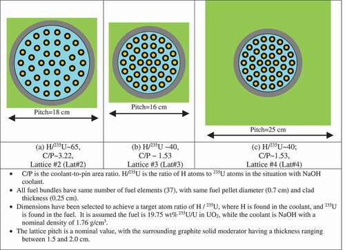
As shown in , there are three different lattice concepts (lattice 2, lattice 3, and lattice 4) and all use a square lattice pitch similar to PWRs and PT-HWRs. All use a 37-element fuel bundle, with the same fuel composition and geometric specifications for the fuel elements. Each lattice has the fuel bundle inside a 1-cm-thick graphite fuel channel tube surrounded by an external graphite moderator, or potentially various hydroxide-based external moderators [such as 7LiOH, 7LiOD, Mg(OD)2, or ZrE(OD)4]. However, lattice 2 and lattice 3 use different pitch circle radii for the four rings of fuel elements.
The diameter of the coolant channel was adjusted such that a certain ratio of hydrogen atoms (in the hydroxide coolant) to 235U atoms (in the UO2 fuel) would be achieved. The hydrogen/uranium (H/U) ratio impacts the thermalization of neutrons and the neutron energy spectrum. Typically, a PWR lattice has an H/U ratio of ~130 for UO2 fuels with 2.6 wt% 235U/U enrichment,Citation18 although more modern designs with higher fuel enrichment (~5 wt% 235U/U) will have a much lower ratio (perhaps H/U ~ 65).
The H/U ratio is an approximate metric and the “optimum” value of H/U, the value which maximizes the lattice reactivity, and will vary depending on the design of the lattice, whether it is a homogeneous mixture of a hydrogen-based compound mixed with a uranium-based compound or a more heterogeneous design (such as fuel elements in fuel assemblies or fuel bundles/fuel stringers in fuel channels with an separate moderator region). A fuel bundle/fuel stringer in a fuel channel with an external moderator is considered to be the most heterogeneous design concept, and its optimum H/U ratio is expected to be different from that of a simple homogeneous mixture of all materials of all components within the lattice cell. The optimum value of H/U will also depend on the presence of other compounds and chemical elements that may impact neutron absorption and moderation, such as structural materials, fertile materials (such as 238U), and other materials that may cause moderation as well [oxygen (in oxide fuel and in hydroxides), carbon (in graphite), and alkali metals found in hydroxides (Li, Na)]. However, as mentioned previously, it is expected that the results of these studies for fuel bundles/fuel clusters in fuel channels will be generally similar to what might be obtained for a square or hexagonal fuel assembly, provided that the thermal-to-total-neutron-flux ratio of the lattice is similar. At the very least, the results from these studies will indicate trends that could be applied in scoping studies for fuel assemblies.
For this study, the channel diameters were determined for H/U = 65 (for lattice 2) and H/U = 40 (for lattices 3 and 4), assuming that the hydroxide coolant was NaOH (coolant 2, Cool2). A test lattice with H/U = 130 (referred to as lattice 1) was also developed, but the performance results were considered inferior and are not shown in this paper. The pitch circle radii were adjusted such that each fuel element would be surrounded by approximately the same volume of coolant, analogous to what is found in a 37-element fuel bundle in a PT-HWR (Refs. 1, 52, and 53). The fuel bundle and channel design for lattice 4 is the same as that for lattice 3, with H/U = 40, but with lattice 4 a larger lattice pitch was used (25 cm) to accommodate a larger volume of external moderator.
II.D. Potential SMR Cores Using Proposed Lattice Concepts
It is intended that these various lattices could be used in an SMR concept with a bare core size of diameter = height = 163.345 cm. These bare core dimensions correspond to a total buckling of 1.237E−3 cm−2. The dimensions were chosen such that a core with a lattice using 7LiOH as a coolant with H/U = 65 (and a lattice pitch of 15 cm) would have a core uranium mass of ~2000 kg. In earlier studies not described in detail here, 7LiOH (coolant 1, Cool1) was also considered as a potential hydroxide coolant, although it has a much higher melting point (~462°C). With an assumed specific power of ~15 kW/kg, such a core would be able to generate a total core power of 30 MW(thermal), a nominal power level that is desirable for a smaller-sized SMR. As will be seen later, the actual uranium mass and specific power used are different from those used in the initial assumptions.
The nominal design specifications of a proposed SMR operating with hydroxide coolants and/or external moderators are shown in . The geometric specifications for the 37-element fuel bundle to be cooled by 7LiOH/NaOH or FLiBe in lattices with different lattice pitches and different H/U ratios are shown . The material densities and nominal temperatures of different components and the specific power used in lattice physics calculations are shown . For the purpose of carrying out initial exploratory lattice physics calculations, a nominal fuel temperature of 1200°C was assumed, based on the fact that previous studies of the SmAHTR (CitationRef. 3) where cylindrical fuel elements in fuel bundle clusters cooled by FLiBe had a peak fuel temperature of less than 1200°C. The outer SiC clad was set to be the outlet temperature of the coolant (~700°C), while the inner graphite clad was set to be at a nominal intermediate temperature (~1000°C). It is recognized that these nominal component temperatures will need to be revised and updated following more detailed thermal-hydraulic calculations to be carried out in future studies. However, for the purpose of carrying out initial lattice physics calculations, these assumed values for temperature were considered adequate.
TABLE III Nominal Design of a SMR Operating with Hydroxide Coolants and/or External Hydroxide Moderators
TABLE IV Geometric Specification of 37-Element Fuel Assemblies
TABLE V Geometric Specifications of Rings of 37-Element Fuel Assemblies*
TABLE VI Material Densities and Specific Power for 37-Element Fuel Assemblies
TABLE VII Operating Temperatures for Components for Lattices
Lattices 2 and 3 were initially set up to use a graphite external moderator, as shown in . Lattice 4 was set up to test either graphite or 7LiOD as external moderators. It was later realized that there may be insufficient moderation provided by the graphite external moderator, and so it was decided to also test 7LiOH as an external moderator for lattices 2 and 3. Subsequently, it was also realized that deuteroxides such as Mg(OD)2 and ZrE(OD)4 might be used instead of 7LiOD as external moderators, given their higher deuterium density and the lower thermal neutron absorption cross section of Mg (~56 mb) or enriched zirconium (ZrE, 95 wt% 90Zr/Zr) (~27 mb) compared to enriched lithium (7Li) (~82 mb). Thus, these moderators were tested for lattices 4 and 2 to see what improvements in the lattice reactivity and reductions in the neutron migration area and neutron leakage could be achieved.
The expected number of fuel channels/assemblies required in the bare SMR core is different for each lattice type and varies from 33.5 (for lattice 4, with a 25-cm pitch) to 64.7 (for lattice 2, with an 18-cm pitch) to 81.9 (for lattice 3, with a 16-cm pitch), as shown in . In a more practical core design, an integer number of fuel channels would be used, and it would also be preferable for the core to have symmetry. Examples of such possible cores for lattices 2, 3, and 4 are shown in . Thus, the actual effective core diameter may be made larger or smaller than the target value of 163.345 cm. However, the core height could be adjusted (height < diameter or height > diameter) to achieve the same total core mass and to have a similar total core buckling. While achieving a core that is as close as possible to a right cylinder (diameter = height) is highly desirable to minimize the neutron leakage for a given core volume, it is not an absolute requirement.
TABLE VIII Core Mass and Power Levels
Fig. 2. Possible SMR core layouts using lattice concepts lattice 2, lattice 3, and lattice 4
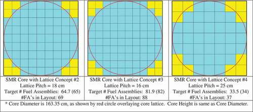
As shown in , the total heavy metal (HM) mass of uranium in the SMR core with diameter = height = 163.345 cm will vary from 722 kg (using lattice 4) to 1392 kg (using lattice 2) to 1761 kg (using lattice 3), which is comparable to the initial assumption of 2000 kg used in design estimates. With an imposed core average specific power limit of 35 kW/kgHM, which is somewhat higher than that found in PT-HWRs (~24 kW/kgHM) (CitationRef. 1) and PWRs (~28 kW/kgHM) (CitationRef. 18), the core power levels could range from 25 MW(thermal) (using lattice 4) to 49 MW(thermal) (using lattice 2) to 62 MW(thermal) (using lattice 3).
III. METHODS AND ANALYSES
III.A. Codes and Libraries
The lattice physics code WIMS-AECL version 3.1.2 (CitationRef. 54), in conjunction with an 89-group nuclear data library based on ENDF/B-VII.0 (CitationRef. 55), was used to perform two-dimensional lattice physics calculations. WIMS-AECL was used to model the various lattices described previously involving a 37-element fuel bundle inside a graphite fuel channel tube cooled with 7LiOH/NaOH or FLiBe and moderated externally by various moderators [such as graphite, 7LiOH, 7LiOD, Mg(OD)2, or ZrE(OD)4]. It is noted that the 89-group library used with WIMS-AECL does not have burnup data for Li, Be, Na, Mg, or F. Thus, the isotopes of these elements used in coolant and/or moderator materials will not deplete or transmute, although expected transmutation isotopes will be relatively short-lived or will have relatively low neutron cross sections (typically less than 0.2 bn).
WIMS-AECL has been used in previous studies for modeling lattices with hydrogen-based coolants and/or moderators, such as PT-HWRs (Refs. 52 and 53) and the ACR-1000 reactor (with light water coolant).Citation56Citation57-58 To date, WIMS-AECL has not yet been tested for modeling lattices involving molten salts or hydroxides. However, for the purpose of exploratory scoping studies, WIMS-AECL was considered adequate. The WIMS-AECL model was based on that used in previous studiesCitation52,Citation53 for modeling PT-HWRs with various types of advanced fuels. The geometry and dimensions of various components were modified, along with material isotopic composition specifications, densities, and temperatures. In addition, because the moderating properties of hydroxides and graphite are quite different from heavy water, it was necessary to make changes in the spatial discretization used in the numerical solution of the integral neutron transport equation, which essentially involved using a much finer computational mesh.
The WIMS-AECL model was set up with approximately 200 burnup steps (nonuniform in time step size) to achieve a maximum burnup of ~160 MWd/kg at 5100 days of burnup with a constant specific power. The user specifies the time step size. Initially, at low levels of burnup, the time step sizes were set to be small (0.1 to 1.0 day) and were increased to larger values (2, 5, 10 days) as the fuel approached higher levels of burnup, and then to even larger time step sizes (20, 50 days) at burnup levels where the change in reactivity (k-infinity) with burnup tends to be more gradual as the fissile fuel is depleted. The value of k-infinity, critical buckling, k-effective, and other physics data were computed at each burnup step by WIMS-AECL. To compute k-effective, a user-specified input buckling value of BCitation2 = 1.237E−3 cm−2 was used, corresponding to a bare core with diameter = height = 163.345 cm. The calculation of k-effective is a post-transport calculation edit performed by WIMS-AECL using a user-specified input buckling (with radial and axial components), and it is computed using a multigroup solution with a diffusion leakage approximation and isotropic diffusion coefficients at each burnup step. However, the burnup calculations at each burnup step actually use the “critical buckling,” which is computed internally by WIMS-AECL using a critical buckling search. Thus, the burnup calculations are always performed in a critical neutron energy spectrum (k-effective = 1.0) using the critical buckling.
III.B. Calculations and Performance Metrics
The various lattices described previously were tested with both 7LiOH/NaOH and FLiBe coolants with graphite external moderator. The use of 7LiOH as an external moderator was tested for lattice 2 and lattice 3, which are tight pitched. The use of 7LiOD as an external moderator was only tested for lattice 4. The use of Mg(OD)2 and ZrE(OD)4 as external moderators were tested only for 7LiOH/NaOH coolant in lattice 2 and lattice 4.
Based on the data extracted from the lattice physics calculations with WIMS-AECL for the various test cases of the different lattice concepts cooled and/or moderated by hydroxides, several performance metrics were evaluated, including infinite multiplication factor (k-infinity), effective multiplication factor (k-effective), leakage reactivity, thermal-to-total-neutron-flux ratio, critical buckling (BCitation2critical), migration area (M2) and migration length (M), critical diameter (Dcrit), BU, FU and relative fissile utilization (RFU), UU and relative uranium utilization (RUU), nominal reactor power, core power density, core lifetime at rated power, core lifetime at 25-MW(thermal) nominal power, and other parameters.
III.B.1. Infinite and Effective Multiplication Factors and Leakage Reactivity
The k-effective is evaluated by WIMS-AECL at each burnup step using an input bucking of BCitation2input = 1.237E−3 cm−2, which corresponds to the buckling for a bare right-cylinder core with diameter = height = 163.345 cm based on textbook analytical expressionsCitation19:
It is assumed a priori that any reactivity losses due to neutron absorption by other structural components in the SMR core with the proposed lattices is negligible, at least compared to the total reactivity of the lattice. For the purpose of exploratory scoping studies, this simplifying approximation was considered adequate. The reactivity losses due to the anticipated use of control devices to hold down the excess reactivity were also ignored for the purpose of this study.
The leakage reactivity is the difference between k-infinity and k-effective, where leakage reactivity = (k-infinity − k-effective) × 1000 [in units of milli-k (mk)]. Ideally, the neutron leakage should be kept as low as possible. In a large-scale reactor, such as a 700-MW(electric) class PT-HWR or even a 1000-MW(electric) class PWR, the leakage reactivity for the fuel in a core average burnup is typically 30 to 35 mk (3000 to 3500 pcm). However, for much smaller reactor cores, the neutron leakage or reactivity leakage is going to be much larger, especially if the migration area for the fuel/lattice cell is much larger. To minimize leakage reactivity, either the core can be made larger, which makes the input buckling smaller, or the lattice concept can be designed to minimize the migration area.
III.B.2. Thermal-to-Total-Neutron-Flux Ratio
The WIMS-AECL calculations provide the lattice cell–averaged thermal neutron flux and the total neutron flux at each burnup step. The ratio of the thermal flux to the total flux is an indicator of how well thermalized the neutrons in the reactor are. It is generally expected that having a high ratio is desirable in order to maximize the probability of thermal fission of 235U and other fissile isotopes (such as 239Pu and 241Pu). However, lower values of the thermal-to-total-neutron-flux ratio may be desirable in certain circumstances to increase the amount of fast fissions that will occur in 238U. In conventional light water reactors, the thermal-to-total-flux ratio is on the order of 0.14 to 0.18 (Refs. 17 and 18).
III.B.3. Buckling, Migration Area, and Critical Diameter
To a first approximation, the buckling is an indicator of the curvature of the neutron flux. Higher positive values of critical buckling mean that the core can be made smaller and still maintain criticality. The situation of zero buckling indicates that the lattice in a reactor will not go critical unless it is infinitely larger. A negative value of critical buckling indicates that such a reactor will always be subcritical, no matter how large it is made.
The M2 is based on the value of k-infinity and the value of the critical buckling computed by WIMS-AECL at each burnup step and is given by
The migration area is an indicator of how much leakage can be expected in the core, given that in the one-group approximation the effective multiplication factor is related to the infinite multiplication factor by
Thus, cores of a fixed size (and buckling) with lattices with a much lower migration area should experience much less neutron leakage and a lower leakage reactivity.
The critical diameter of the bare right cylindrical core (diameter = height) is determined from the critical buckling from:
III.B.4. Burnup, FU, and UU
The BU is defined by the value of burnup at which the computed value of k-effective is 1.000 using the input buckling provided. This value of BU is relevant for a core with single-batch refueling.
The FU is the BU divided by the initial fissile mass fraction in the fuel or FU = BU/0.1975. The RFU is the FU normalized by the FU that is typical for a PT-HWR operating with natural uranium fuel. For example, the FU for a PT-HWR with natural uranium (NU) fuel is approximately 1056 MWd/kg-fissile = 7.5 MWd/kg/0.0071. Thus, RFU = FU (in MWd/kg-fissile)/1056 MWd/kg-fissile. It is desirable to maximize the FU in order to minimize fuel costs.
The UU is the BU divided by the enrichment factor for producing 19.75 wt% 235U/U–enriched uranium from mined natural uranium, assuming 0.2 wt% 235U/U in the tails (the depleted uranium) in the enrichment process. The enrichment factor for 19.75 wt% LEU is 38.3 kg of NU/kg of LEU = (19.75 to 0.2)/(0.71 to 0.2). Thus, UU = BU/38.3. The RUU is the UU normalized by the UU that is typical for a PT-HWR operating with NU fuel. For example, the UU for a PT-HWR with NU fuel is approximately 7.5 MWd/kg-Umined. Thus, RUU = UU (in MWd/kg-Umined)/7.5 MWd/kg-Umined. It is desirable to maximize the UU in order to minimize fuel costs.
III.B.5. Core Mass and Power and Lifetime
With a fixed volume of the core and a given lattice design, the total fuel mass in the core will be fixed. Subsequently, assuming a core average specific power of 35 kW/kgHM, the maximum expected power of the reactor can be determined. The core power density is simply the total reactor power divided by the volume of the core. To minimize capital costs of an SMR, it is desirable to maximize the core power density.
The theoretical maximum core lifetime is how long a reactor can operate before it needs to be refueled to maintain criticality. This estimate does not account for effect reactivity losses and the reduction in burnup due to other structural components not modeled in the lattice physics model, nor reactivity devices used to hold down the excess reactivity in a reactor core [similar to the effect of control blades in a boiling water reactor (BWR)]. For an SMR core with a single-batch refueling scheme, the core lifetime is estimated by dividing the BU by the core average specific power in the fuel. Thus, core lifetime = BU (in MWd/kg) × 1000 kWd/kg/35 kW/kg. The core lifetime can be rescaled to a fixed core power of 25 MW(thermal). Thus, a reactor that may be capable of operating at 82 MW with a 35 kW/kg specific power limit may be reduced in power level to 25 MW(thermal), allowing the reactor to operate longer. Thus, the core lifetime [at 25 MW(thermal)] = core lifetime (at nominal power) × nominal power/25 MW(thermal). For an SMR, it is desirable for the core lifetime to be 10 years or more before refueling to minimize operational costs.
IV. RESULTS
IV.A. Infinite Multiplication Factor
Plots of k-infinity versus burnup for the various lattices are shown in for lattices 2, 3, and 4 with the different coolants (Cool4 = 7LiOH/NaOH or Cool7 = FLiBe) and the different external moderators [graphite, 7LiOH, 7LiOD, Mg(OD)2, ZrE(OD)4]. With an initial uranium fissile content of 19.75 wt% 235U/U, the initial reactivity is quite high, ranging between k-infinity = 1.500 and 1.650 for both the 7LiOH/NaOH- and FLiBe-cooled lattices, and dropping down to k-infinity = 1.000 at burnups between 130 and 160 MWd/kg. The key exceptions are the FLiBe-cooled lattices with graphite moderator in lattices 2 and 3, which have a significantly reduced reactivity ranging from k-infinity ~ 1.300 at zero burnup to k-infinity = 1.000 at ~75 MWd/kg burnup.
Fig. 3. k -infinity versus burnup: lattice 2
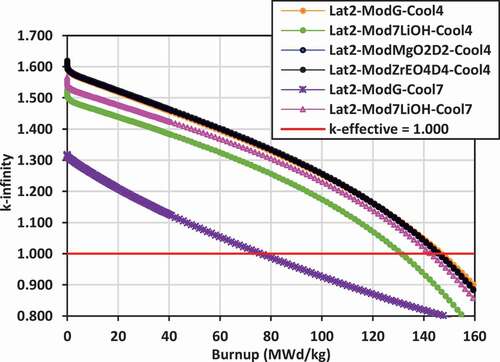
Fig. 4. k -infinity versus burnup: lattice 3.Cool4 is 7LiOH/NaOH and Cool7 is FLiBe
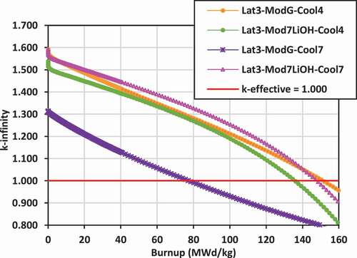
Fig. 5. k-infinity versus burnup: lattice 4
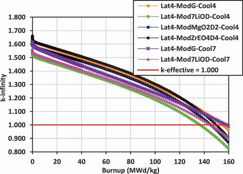
Replacing the graphite moderator with 7LiOH leads to a reduction in the reactivity for lattices 2 and 3 for the 7LiOH/NaOH-cooled lattices (between 50 and 100 mk), but a dramatic increase for lattices 2 and 3 with FLiBe coolant (between 250 and 300 mk). Replacing the graphite moderator with Mg(OD)2 or ZrE(OD)4 leads to a slight increase in the reactivity for lattices 2 and 4 for 7LiOH/NaOH-cooled lattices.
For lattice 4, the reactivity with 7LiOD as the external moderator is less than that of using graphite by 100 to 150 mk. In terms of maximizing reactivity for the lattices cooled with 7LiOH/NaOH, the moderators Mg(OD)2 and ZrE(OD)4 are superior to graphite, while 7LiOD appears to be inferior. For the lattices cooled with FLiBe, 7LiOH as an external moderator is superior to graphite for the tight-pitched lattices 2 and 3. For the wider-pitched lattice 4, graphite is superior to 7LiOD. However, as will be seen in Sec. IV.B, the use of 7LiOH and 7LiOD as external moderators will help significantly reduce neutron leakage, allowing higher burnups for the lattices with FLiBe coolant.
IV.B. Effective Multiplication Factor
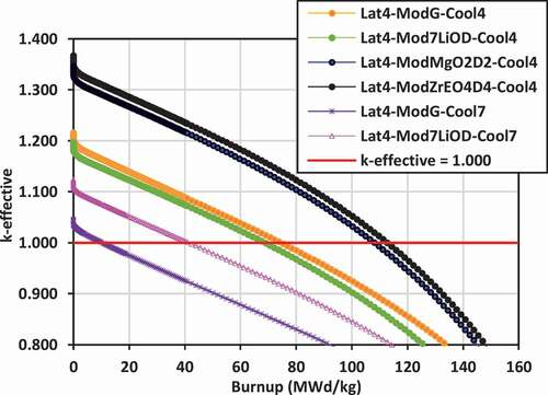
Plots of k-effective versus burnup for the various lattices are shown in for lattices 2, 3, and 4.
Fig. 6. k -effective versus burnup: lattice 2
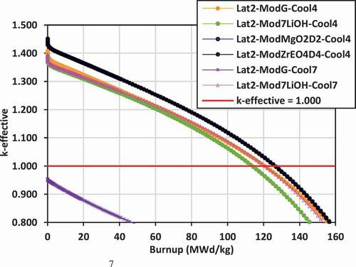
Fig. 7. k -effective versus burnup: lattice 3
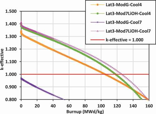
Fig. 8. k -effective versus burnup: lattice 4
The most reactive lattice with the highest k-effective values are those for lattice 2 with ZrE(OD)4, Mg(OD)2, and graphite external moderators and with 7LiOH/NaOH coolant, followed by lattice 3 with FLiBe coolant/7LiOH moderator and 7LiOH/NaOH coolant/7LiOH moderator. For lattice 2, replacing the graphite moderator with 7LiOH for the cases with 7LiOH/NaOH coolant leads to a slight reduction in the value of k-effective, ranging between 20 and 40 mk. However, for lattice 3, which is at a smaller pitch than lattice 2, replacing the graphite with 7LiOH increases the k-effective for the case with 7LiOH/NaOH coolant by 40 to 60 mk.
In lattice 2 and lattice 3, the use of 7LiOH instead of graphite for the external moderator for the case of FLiBe coolant dramatically improves neutron moderation, reduces neutron leakage, and increases the value of k-effective relative to that for graphite moderator, ranging between 350 and 450 mk.
In lattice 4, the highest values of k-effective are achieved with 7LiOH/NaOH coolant with ZrE(OD)4 and Mg(OD)2 moderators. Due to severe undermoderation and neutron leakage, the k-effective values are lowest for the lattices cooled with FLiBe and moderated with graphite, similar to what is observed for lattice 2 and lattice 3. By switching to 7LiOD external moderator, neutron leakage is reduced significantly for the case of FLiBe coolant, and the k-effective is increased by ~80 mk.
Thus, to maximize k-effective, the use of external moderators ZrE(OD)4 and Mg(OD)2 are superior to graphite, 7LiOD, and 7LiOH moderators for 7LiOH/NaOH coolants. As an external moderator, 7LiOH is superior to graphite for lattice 3. Similarly, 7LiOH is superior to graphite for lattice 2 and lattice 3 for FLiBe coolant, while 7LiOD is superior to graphite for lattice 4 for FLiBe coolant. Although results are available, it is expected that ZrE(OD)4 and Mg(OD)2 will be superior to 7LiOD for lattice 4 for FLiBe coolant as well. These results demonstrate that the use of hydrogen-based external moderators helps to reduce neutron leakage significantly, relative to the use of a graphite external moderator.
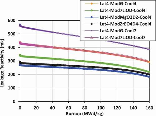
IV.C. Leakage Reactivity
Plots of leakage reactivity (k-infinity − k-effective) versus burnup for the various lattices are shown in for lattices 2, 3, and 4.
Fig. 9. Leakage reactivity: lattice 2
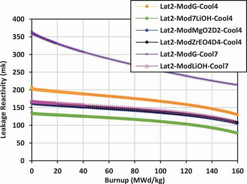
Fig. 10. Leakage reactivity: lattice 3
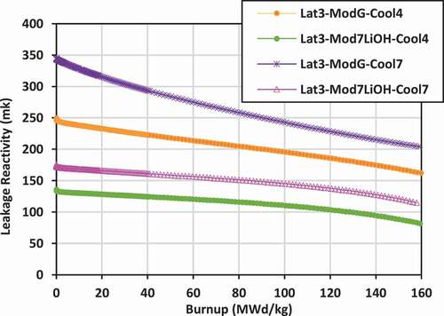
Fig. 11. Leakage reactivity: lattice 4
For lattice 2, the leakage is lowest for the case of 7LiOH/NaOH coolant with 7LiOH external moderator, ranging from 130 to 80 mk. The leakage values are comparable for the cases with Mg(OD)2 and ZrE(OD)4 with 7LiOH/NaOH coolant and for 7LiOH moderator with FLiBe coolant, ranging from 170 to 110 mk. Leakage is much higher for the cases with graphite moderator, ranging from 200 to 130 mk for 7LiOH/NaOH coolant and from 360 to 210 mk for FLiBe coolant.
The leakage behavior for lattice 3 is similar to that for lattice 2. Again, the neutron leakage is lowest for the case of 7LiOH/NaOH coolant with 7LiOH external moderator, ranging from 130 to 80 mk, while the highest neutron leakage is that for the case of graphite moderator with FLiBe coolant, ranging from 350 to 200 mk.
For lattice 4, the neutron leakage is typically larger than that found in lattice 2 or lattice 1 for the same combination of coolants and moderators. In lattice 4, the neutron leakage is lowest for the cases of 7LiOH/NaOH coolant with Mg(OD)2 and ZrE(OD)4 moderators, ranging from 300 to 180 mk, and it is somewhat higher for 7LiOD moderator, ranging from 350 to 220 mk. The leakage for 7LiOH/NaOH coolant with graphite moderator and FLiBE coolant with 7LiOD moderator are approximately the same, ranging from 440 to 300 mk. The highest leakage is that for FLiBe coolant with graphite moderator, ranging from 560 to 380 mk.
These results clearly demonstrate the advantage of using hydrogen-based moderators for reducing neutron leakage and the effectiveness of using 7LiOH, Mg(OD)2, and ZrE(OD)4.
IV.D. Migration Length
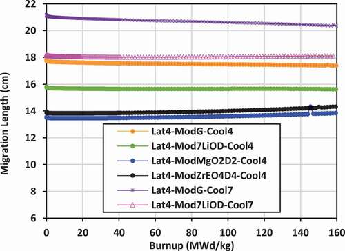
Results shown previously for k-effective and neutron leakage are corroborated by the results for the migration length for the various lattices. Lattices with the lowest values of migration length will also experience the lowest levels of neutron leakage. Plots of the migration length versus burnup for the various lattices are shown in for lattices 2, 3, and 4.
Fig. 12. Migration length: lattice 2
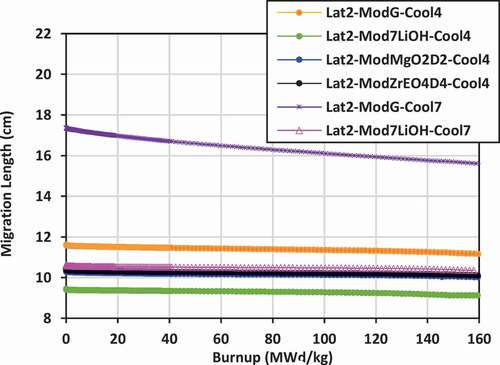
Fig. 13. Migration length: lattice 3
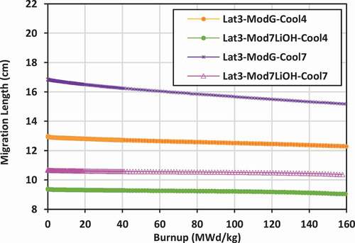
Fig. 14. Migration length: lattice 4
For lattice 2, the lowest migration length is that for 7LiOH/NaOH coolant with 7LiOH external moderator, ranging from 9.4 to 9.1 cm, while the highest is that for FLiBe coolant with graphite moderator, ranging from 17.3 to 15.6 cm. The use of a hydrogen-based coolant, such as 7LiOH/NaOH, is effective in reducing the migration length, as is using a hydrogen-based external moderator. Similarly, the use of Mg(OD)2 and ZrE(OD)4 are also effective in reducing the migration length relative to graphite.
For lattice 3, the results are very comparable to those of lattice 2. The lowest migration length is that for 7LiOH/NaOH coolant with 7LiOH external moderator, ranging from 9.3 to 9.0 cm, while the highest is that for FLiBe coolant with graphite moderator, ranging from 16.8 to 15.2 cm.
For lattice 4, which has a larger lattice pitch (25 cm) and a larger volume of external moderator, the migration distance is larger than that in lattice 2 or lattice 3 for the same combination of coolant and moderator. The lowest migration distance is that for 7LiOH/NaOH coolant with Mg(OD)2 and ZrE(OD)4 moderators, ranging from 13.5 to 14.3 cm. The largest migration distance is that for FLiBE coolant with graphite moderator, ranging from 21 to 20.3 cm. The use of 7LiOD as an external moderator instead of graphite is a definite improvement, reducing the migration distance by 2 to 3 cm. The higher deuterium number density of Mg(OD)2 and ZrE(OD)4 (as shown previously in ) allows a further reduction of the migration length by 1.5 to 2.5 cm relative to that of 7LiOD. To minimize the migration length for lattices 2 and 3, it is best to use 7LiOH as an external moderator, while for lattice 4, it is best to use Mg(OD)2 or ZrE(OD)4.
IV.E. Thermal-to-Total-Flux Ratio
Plots of the ratio of the lattice cell–averaged thermal neutron flux to the total neutron flux versus burnup for the various lattices are shown in for lattices 2, 3, and 4.
Fig. 15. Thermal/total flux: lattice 2
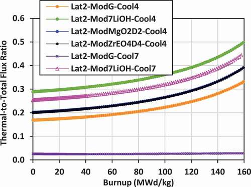
Fig. 16. Thermal/total flux: lattice 3
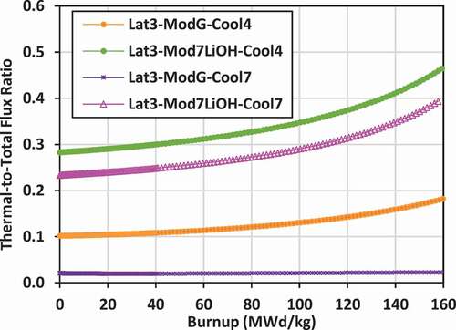
Fig. 17. Thermal/total flux: lattice 4
The flux ratio gives an indication of the neutron energy spectrum. Typically, PT-HWRs with NU fuel have a thermal-to-total-flux ratio of approximately 0.6 to 0.7, indicating a well-thermalized neutron energy spectrum. For comparison, large PWRs with enriched fuel (~3 wt% 235U/U), such as the 1000-MW(electric) Indian Point 2, have a flux ratio ranging from 0.14 to 0.16 (CitationRef. 18), while a small PWR [such as the prototype 76-MW(thermal) N.S. Savannah naval reactor from the 1960s] has a flux ratio of approximately 0.18 (CitationRef. 17). Thus, reactors moderated with light water (containing hydrogen) tend to have a harder neutron energy spectrum than those moderated with heavy water (containing deuterium) or graphite, although the thermalization will depend on the volume of external moderator and the amount of moderation that occurs within the coolant.
The plots of the flux ratio show that the energy spectrum of the lattices cooled with 7LiOH/NaOH and moderated with graphite tend to be comparable or slightly more thermalized than that of a PWR. The flux ratios for these coolant/moderator combinations range from 0.17 to 0.39 (for lattice 2), 0.10 to 0.182 (for lattice 3), and 0.22 to 0.385 (for lattice 4). As the fissile fuel 235U is depleted, the spectrum becomes more thermalized with burnup.
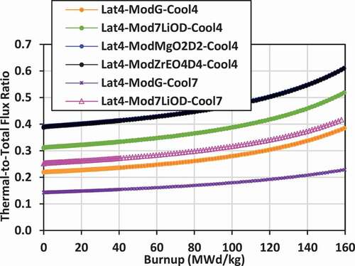
The use of Mg(OD)2 and ZrE(OD)4 increases the thermalization of neutrons, particularly for lattice 4 where there is a larger lattice pitch and volume of external moderator. For lattice 2, the flux ratio for these moderators ranges from 0.2 to 0.39. For lattice 4, the flux ratio ranges from 0.39 to 0.61, the most thermalized of all the lattices. In this case, the spectrum is more thermalized than a PWR, but somewhat less thermalized than that of a typical heavy water reactor (flux ratio between 0.6 and 0.7).
The use of 7LiOH as an external moderator also increases the thermalization of neutrons for lattice 2 and lattice 3 relative to graphite, 7LiOD, Mg(OD)2, and ZrE(OD)4. The flux ratio for these cases ranges from 0.29 to 0.5 for lattice 2 and from 0.28 to 0.46 for lattice 3.
The lattices that are the least thermalized are those with FLiBe coolant and graphite external moderator. For lattice 2, the flux ratio ranges from 0.025 to 0.028. For lattice 3, the flux ratio ranges from 0.021 to 0.023. These lattices are effectively fast-spectrum lattices, not thermal. For lattice 4, with a much larger volume of external moderator, the flux ratio for FLiBe with graphite moderator ranges from 0.14 to 0.23, which becomes comparable to that of a PWR.
Thus, in comparison to other reactors, the lattices cooled and/or moderated with hydroxides tend to be comparable or more thermalized than PWRs, but less thermalized that PT-HWRs. When FLiBe coolant and graphite moderator are used in a tight lattice pitch (16 to 18 cm), the neutron energy spectrum is essentially a fast spectrum.
IV.F. Critical Diameter
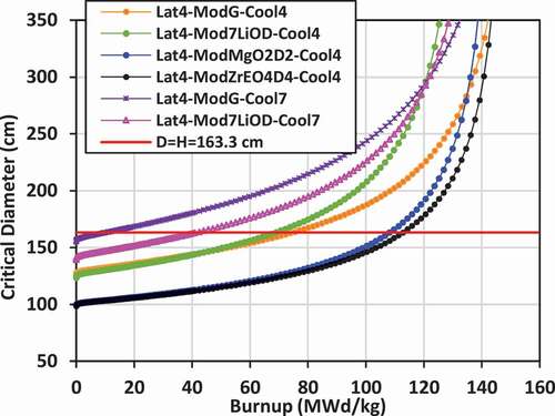
Using the critical buckling data computed by WIMS-AECL at each burnup step for each lattice, the approximate critical diameter for a bare lattice in the form of a right cylinder (diameter = height) can be inferred, given that BCitation2crit = (π/Hcrit)Citation2 + (2.405 × 2/Dcrit)Citation2. Plots of the critical diameter versus burnup for the various lattices are shown in for lattices 2, 3, and 4. The value diameter = height = 163.345 cm corresponding to the selected size for the bare right-cylinder SMR core and corresponding to the input buckling used in the lattice calculations (BCitation2input = 1.237E− cm−Citation2) is also shown on the plots for comparison. The value of burnup at which the critical diameter of the core matches the input diameter is the BU for a single-batch SMR core. If the critical diameter is larger than the input diameter, then the core cannot achieve criticality.
Fig. 18. Critical diameter: lattice 2
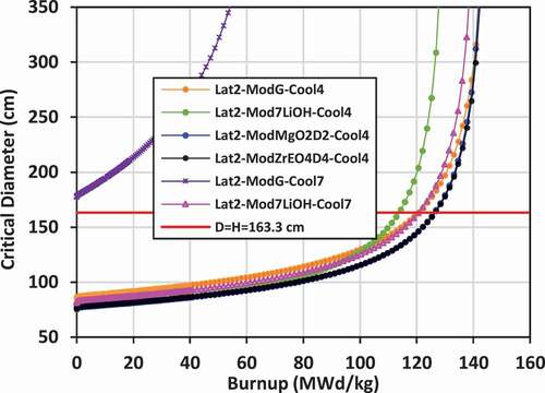
Fig. 19. Critical diameter: lattice 3
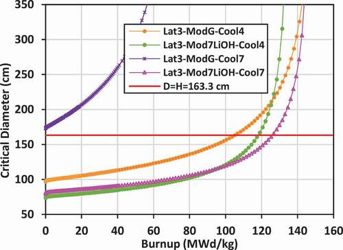
Fig. 20. Critical diameter: lattice 4
The input diameter chosen for these studies (diameter = height = 163.345 cm) is near the inflection point for the critical diameter versus burnup curve. This statement suggests that the chosen diameter (163.345 cm) is near optimum for maximizing the burnup while minimizing the diameter. For example, as shown for lattice 2 with graphite external moderator, and for the case with 7LiOH/NaOH coolant, the BU is approximately 121 MWd/kg with diameter = height = 163.345 cm. If the diameter is increased by ~25% to ~204 cm, the BU will increase to ~131 MWd/kg, which is just an 8.3% increase. Thus, while increasing the size of the core is advantageous for increasing core power, significant gains in burnup will not be achieved in further reducing neutron leakage for 7LiOH/NaOH-cooled lattices.
For lattice 2 and lattice 3, the maximum burnup appears to reach a nearly asymptotic value between 120 and 150 MWd/kg at diameters greater than 300 cm. The FLiBe-cooled/graphite-moderated lattices, which have a fast spectrum, reach an asymptotic burnup between 70 and 75 MWd/kg, but require a diameter over 1000 cm. For lattice 4 with graphite or 7LiOD moderator, and especially those with FLiBe coolant, it is very advantageous to increase the core size. What is particularly interesting (as shown in ) is that at a critical diameter of ~300 cm, there is an intersection of three curves for the two FLiBe-cooled cases and the 7LiOD/NaOH-cooled case with 7LiOD moderator, where the burnup is ~120 MWd/kg. For cores larger than 300 cm, graphite is superior to 7LiOD as a moderator.
IV.G. Exit Burnup, Nominal Core Lifetime, Spent Fuel Composition, and Reactivity Swing
IV.G.1. Exit Burnup
As discussed previously, the estimated BU for the fuel is the value of burnup when k-effective = 1.000 for the given bare SMR core with diameter = height = 163.345 cm. This burnup is a single-batch burnup. If the proposed SMR core was to use multiple batches, similar to what is used by conventional large-scale PWRs, then the BU could be increased further. For example, using a linear reactivity model as an approximation, where BU(n) = 2 n/(n + 1) × BU(n = 1), a three-batch core (n = 3) may be able to achieve a BU that is approximately 50% higher than the burnup for a single-batch core [BU(3) = 2 × 3/(3 + 1) × BU(1) = 1.5 × BU(1)].
Results for the single-batch BU for lattices 2, 3, and 4 are shown in . Exit burnup values for lattices cooled with 7LiOH/NaOH range from 69 MWd/kg (lattice 4 moderated with 7LiOD) to 126.5 MWd/kg (lattice 2 moderated with ZrE(OD)4). For lattice 3, the use of 7LiOH leads to the highest burnup (~118 MWd/kg). Exit burnup values for lattices cooled with FLiBe range from 10 MWd/kg (lattice 4 moderated with graphite) to 126 MWd/kg (lattice 3 moderated with 7LiOH), which is the highest burnup level of all the lattices. The FLiBe-cooled, graphite-moderated lattice 2 and lattice 3 are far too undermoderated to go critical at diameter = 163.345 cm. If the core size were increased to 300 cm, then these fast-spectrum lattices could achieve burnups ranging from 46 to 49 MWd/kg.
TABLE IX Core Power, Fuel Burnup, Lifetime, Spent Fuel 235U Content
TABLE X Comparison of Lattices for Burnup, FU, and UU, and Core Lifetime at 25 MW(thermal)*
The maximum single-batch burnup levels that are potentially achievable with the solid-fuel bundles cooled by 7LiOH/NaOH or FLiBe (up to ~127 MWd/kg) are nearly double those typically obtained in PWRs (60 to 80 MWd/kgHM). These high burnup values are comparable to those (120 to 140 MWd/kgHM) that have been evaluated in previous studies for fluoride-salt-cooled fuel stringers as discussed by Greene et al.Citation3 and Stein et al.Citation5 For comparison, many HTGR designsCitation10 have fuel burnup levels that range between 100 and 200 MWd/kgHM, such as the Fort St. Vrain prototype HTGR that operated in the period of 1979 to 1989 (CitationRef. 18). One of the potential issues with such high-burnup fuels is the irradiation damage to both the fuel and the cladding, even though the fuel concepts proposed in the current study have a relatively thick layer of graphite inner cladding (1.5 mm) and SiC outer cladding (1.0 mm), as shown in . It is expected that future computational physics studies will need be carried out to evaluate fuel performance behavior. As a result of such studies, it may be necessary to consider alternative materials [such as uranium oxy-carbide (UCO) or uranium nitride (UN) instead of UO2 for fuel], additional fuel element clad coatings (such as Inconel to resist corrosion), different clad thicknesses, and other design modifications (such as a central void space in the fuel pellet and an axial plenum for the accumulation of volatile fission product gases).
IV.G.2. Core Lifetime
Using the nominal power levels for the cores with the different lattices and the single-batch burnup values, an estimate of the core lifetime before refueling can obtained. As shown in , the core power levels range from 25 MW(thermal) (using lattice 4) to 48.7 MW(thermal) (using lattice 2) to 62 MW(thermal) (using lattice 3). For the lattices cooled with 7LiOH/NaOH, the core lifetime ranges from 5.3 years (for lattice 4 with 7LiOD moderator) to 9.9 years [for lattice 2 with ZrE(OD)4 moderator]. For the lattices cooled with FLiBe, the core lifetime ranges from 0.8 years (for lattice 4 with graphite moderator) to 9.86 years (for lattice 2 with 7LiOH moderator).
IV.G.3. Spent Fuel Composition
The 235U content in the spent fuel for the various lattices is also shown in . For the lattices cooled with 7LiOH/NaOH, it ranges from 5.91 wt% 235U/U [for lattice 2 moderated with ZrE(OD)4] to 11.95 wt% 235U/U (for lattice 4, moderated with 7LiOD). For the lattices cooled with FLiBe, it ranges from 18.59 wt% 235U/U (for lattice 4 moderated with graphite) to 5.93 wt% 235U/U (for lattice 3 moderated with 7LiOH). With such a high content of 235U remaining in the spent fuel (at least 5.91 wt%), it is expected that it would be desirable to recycle the fuel using one or more of the following options: (1) recycle into a different, large-scale, thermal-spectrum reactor with high neutron economy and requiring a much lower fissile content, such as a PWR (which typically uses fuel with 3 wt% to 5 wt% 235U/U enrichment) or a PT-HWR (which can operate with 0.7 wt% 235U/U enrichment); (2) make new SMR fuel at 19.75 wt% 235U/U through re-enrichment of the spent fuel; or (3) use the spent fuel directly in a larger-size reactor with the same lattice. For example, with regard to the third option, if the spent fuel for lattice 2 with 7LiOH/NaOH coolant and ZrE(OD)4 moderator, which achieves a BU of ~126.5 MWd/kg, was recycled directly into a larger-scale reactor with a core size of diameter = height = 600 cm, then the fuel could achieve a further burnup of ~18 MWd/kg (=144.5 to 126.5), based on the trend of the critical diameter versus burnup data shown in .
The relatively large content of fissile material (235U) remaining in the spent fuel (on the order of 5.9 wt% 235U/U or more) is due to a couple of reasons. The first reason is that the volume of the UO2 fuel is ~34% of the total fuel element volume due to the small-diameter pellet (~0.7 cm), the relatively thick graphite layer (0.15 cm), and the outer SiC clad layer (0.10 cm), as shown in . By comparison, in conventional fuels found in PWRs (Refs. 57 and 58), for example, the volume of the UO2 fuel is ~73% of the total fuel element volume with a pellet diameter of ~0.81 cm, a Zircaloy-4-clad thickness of ~0.061 cm, and an element outer diameter of ~0.95 cm. Thus, although the relative fissile content in the spent UO2 is still quite significant (≥5.9 wt%), it is necessary to recall that the actual fuel pellet volume relative to the fuel element volume is less than half (~47%) that of conventional PWR fuel, and thus, the reactivity (and multiplication factor) of the fuel will be reduced. The second reason why the lattice becomes subcritical, even with a fissile content of more than 5.9 wt% 235U/U in the spent fuel, is that there is a large reactivity loss due to neutron leakage in the small reactor core. As shown previously in , at burnup levels above 100 MWd/kg the neutron leakage from the core can range between approximately 100 and 500 mk.
IV.G.4. Reactivity Swing
A potential issue of concern is the high initial reactivity of the fuel for the various lattice concepts considered in this study. As shown , after the effects of neutron leakage are taken into account, the initial k-effective can range typically from 1.300 to 1.450, with a potential reactivity swing from zero to BU between 300 and 450 mk. Controlling such a change in reactivity swing could become challenging. However, this type of issue is also encountered in small-size PWRs that have been designed for use in naval vessels, such as submarines and aircraft carriers. For example, U.S. naval reactors typically use nuclear fuel made with >93 wt% 235U/U highly enriched uranium (HEU) and are designed to operate for 10 to 30 years before refueling.Citation28,Citation29 Burnable neutron absorbers (BNAs), such as gadolinia (Gd2O3) mixed into the HEU fuel are typically used in conjunction with the control rods to hold down the initial excess reactivity. As the BNA is consumed, especially during the early stages of burnup, greater reliance is placed on the control rods to hold down the excess reactivity. Historically, the target maximum reactivity swing allowed for naval reactors is ≤200 mk, with a maximum allowed k-effective of ~1.240 (CitationRef. 59). The use of alternative control rod designs and neutron-absorbing materials may permit larger values.Citation60,Citation61 It is anticipated and expected that burnable neutron absorbers mixed into the UO2 fuel,Citation28,Citation59 or designed as an integral component of the fuel elementCitation60,Citation61 would need to be used in addition to control rods to control the excess reactivity in the lattice concepts described in the current study.
IV.H. Fissile Utilization and Uranium Utilization
Using the BU for each case and inputting the initial fissile content of the fuel (19.75 wt% 235U/U), the FU was evaluated (FU = BU/0.1975). By comparison, the typical FU for a PT-HWR with NU fuel is approximately 1065 MWd/kg-fissile (7.5 MWd/kgU/0.00711 kg-fissile/kgU). The enrichment factor for converting mined NU into 19.75 wt% 235U/U LEU is approximately 38.3 kg of NU per kilogram of LEU = (19.75 to 0.2)/(0.71 to 0.2), assuming that the tails in the enrichment process are 0.2 wt% 235U/U. Using the BU and the enrichment factor, the UU was evaluated (UU = BU/38.3). The UU was then normalized by the UU for a PT-HWR with NU fuel, which is 7.5 MWd/kg-NUmined.Citation1 Thus, the RUU was simply RUU = UU/(7.5 MWd/kg-NUmined). Since all fuels for all lattices are the same (differing only by their pitch circle radii and the coolant-to-fuel volume ratio), the trends for the FU and UU will be the same as the trends for the BU.
The results for the FU, UU, and RUU for all the different cases are shown in . The RUU is also illustrated in . Typically, the FU is modestly or significantly less than that for a PT-HWR operating with NU fuel. For the lattices cooled with 7LiOH/NaOH, the FU ranges from 348 MWd/kg-fissile (for lattice 4 moderated with 7LiOD) to 640 MWd/kg-fissile [for lattice 2 moderated with ZrE(OD)4], which is nearly 61% of that of a PT-HWR with NU fuel. For the lattices cooled with FLiBe, the FU ranges from 52 MWd/kg-fissile (for lattice 4 moderated with graphite) to 638 MWd/kg-fissile (for lattice 3 moderated with 7LiOH). If three-batch refueling was used, this upper value could be increased by 50% to nearly 91% of the FU a PT-HWR with NU fuel. Similarly, the RUU ranges from 0.036 to 0.44, with the highest values achieved for lattice 2 with 7LiOH/NaOH coolant and Mg(OD)4 moderator.
Fig. 21. Relative uranium utilization
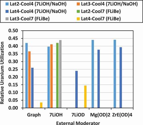
Although the computed values for FU and UU seem low in comparison to a large-scale PT-HWR operating with NU fuel, they must also be put in context and compared with the expected FU and UU of other SMRs using a similar type of fuel (19.75 wt% 235U/U). For example, a variant of the U-Battery concept,Citation62 which is an HTGR-type SMR, achieves a BU of approximately 70 MWd/kg with 17 wt% 235U/U–enriched uranium, with a core size of diameter = 252 cm and height = 320 cm. Thus, the FU is ~412 MWd/kg-fissile, the UU is ~2.14 MWd/kg-NUmined, and the RUU = 0.28. These values are much lower than what is achieved by many of the hydroxide cooled and/or moderated SMR lattices discussed in this study.
IV.I. Reactor Power, Power Density and Core Lifetime at 25 MW(thermal)
The nominal reactor power levels, power densities, and core lifetimes for the fixed-size SMR core (diameter = height = 163.345 cm) for the different lattices are shown . The power level is estimated assuming a fixed specific power of 35 kW/kgHM, which is comparable to that found in high-power fuel assemblies in conventional PWRs with LEUO2 fuel (~35 kW/kgHM), and this value is multiplied by the total HM fuel mass in the core.
The 35 kW/kgHM specific power used in the current studies is comparable to that used in previous studies of fuel element stringers cooled by molten salts, as discussed by Stein et al. in Ref. 5, lower than that found for stringer-type fuel clusters in the SmAHTR (~80 kW/kgHM) (CitationRef. 3), and much lower than the specific power levels (~150 to 200 kW/kgHM) found in previous studies involving pebble-bed fuels cooled by molten salts.Citation4,6,7 In addition, in early studies during the 1950s during the ANP, compact reactors using thin plate-type enriched uranium fuel clad with Inconel and cooled and moderated with molten NaOH were designed to achieve very high power densities and operating temperatures.Citation24 In a number of the fuel and core concepts considered, the specific power levels were estimated to range between 2000 and 6000 kW/kgHM, with a peak fuel temperature of 800°C and a peak coolant temperature of 660°C.
As illustrated in , with smaller lattice pitches, more fuel assemblies can be fitted into the fixed-size core with lattice 2 (18-cm lattice pitch) and lattice 3 (16-cm lattice pitch), and thus, with a fixed specific power level, higher reactor powers are possible. As shown in , the reactor power varies from 25.2 MW(thermal) (for lattice 4) to 48.7 MW(thermal) (for lattice 2) to 61.7 MW(thermal) (for lattice 3). The power level is independent of the coolant, assuming that the thermal-hydraulic behavior of the different coolants will be adequate to ensure a satisfactory thermal-hydraulic margin (fuel and clad do not melt and do not come close to melting under normal operations).
If a net conversion efficiency of 40% is applied, which is conceivable with a primary circuit exit coolant temperature of 700°C, then the net electrical power generation in these cores varies from 10.1 MW(electric) (for lattice 4) to 19.5 MW(electric) (for lattice 2) to 24.7 MW(electric) (for lattice 3). Such power levels [10 to 25 MW(electric)] are within the desired realm of operation of SMRs for remote applications.Citation11
The volumetric core power density varies from ~7.4 MW/mCitation3 (for lattice 4) to 14.2 MW/mCitation3 (for lattice 2) to 18.0 MW/mCitation3 (for lattice 3). By comparison, a conventional large-scale PWR [such as Indian Point 2 (CitationRef. 18)] has a volumetric power density of over 90 MW/mCitation3, while a small-scale PWR (such as the N.S. Savannah naval reactorCitation17) has a volumetric power density of 23 MW/mCitation3. The previously mentioned U-BatteryCitation62 has a volumetric power density of approximately 1.9 MW/mCitation3. Hence, for the same power level, the proposed SMR concepts cooled and/or moderated by hydroxides are much more compact than a sample HTGR-based SMR at the same power level.
Estimates of the operational lifetimes of the fixed-size (diameter = height = 163.345 cm) bare SMR cores operating with single-batch refueling, and at the rated power levels for the different lattices that were discussed previously, are shown in . If the total reactor power is scaled to 25 MW(thermal)/10 MW(electric), then the operational lifetimes of the cores using lattice 2 and lattice 3 can be extended even further, as shown in and . For the fuels cooled with 7LiOH/NaOH, the core lifetimes at 25 MW(thermal) range from 5.4 years (lattice 4 with 7LiOD moderator) to 22.8 years (for lattice 3 with 7LiOH moderator). For the fuels cooled with FLiBe, the core lifetimes at 25 MW(thermal) range from 3.3 years (lattice 4 with 7LiOD moderator) to 24.3 years (lattice 3 with 7LiOH moderator). In addition to increasing the core life, the advantage of reducing the core power to 25 MW(thermal) for lattice 2 and lattice 3 would be to reduce the specific power in the fuel from 35 kW/kgHM to a lower value, which should reduce peak fuel temperatures and enhance thermal-hydraulic margins. This anticipated advantage will need to be confirmed in the future with thermal-hydraulic and heat transfer calculations.
Fig. 22. Core lifetime at 25 MW(thermal)/10 MW(electric)
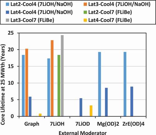
The initial core design specifications described previously in Sec. II.D were constrained to a target nominal specific power of ~35 kW/kg and a core size of diameter = height = 163.345 cm, which for some earlier lattice concepts would give a nominal thermal power of ~30 MW(thermal). The 35 kW/kgHM specific power is a nominal value that is comparable to what is experienced by UO2 in high-power fuel assemblies and fuel bundles in PWRs and PT-HWRs (Refs. 1, 17, and 18). The target thermal power of 30 MW(thermal) [later reduced to 25 MW(thermal)/10 MW(electric)] is a nominal value that is considered desirable for a majority of applications in remote communities.Citation13–15 For lower power demands, such a nominal reactor at a given size could be derated. In situations where greater power is needed, then either multiple units could be built, or if the thermal margins are not exceeded (such as the UO2 fuel getting too close to its melting point), then the specific power constraint could be relaxed. However, as it turns out in this study, the SMR core concepts with the lattice 4 design with a 25-cm pitch are set to operate at ~25 MW(thermal) already, while those cores with the lattice 2 design (18-cm pitch) and the lattice 3 design (16-cm pitch) normally operate at much higher power [~49 MW(thermal) and ~62 MW(thermal), respectively, as shown in ]. Thus, the core concepts with the lattice 2 and lattice 3 designs can be derated to operate at the target value of 25 MW(thermal)/10 MW(electric) and will also operate at lower specific power values (17.9 kW/kgHM and 14.1 kW/kgHM, respectively), giving an even larger thermal margin. It is recognized that the operational lifetime of any reactor core before refueling is required could be increased dramatically by reducing the specific power and power density further, although reducing the core power level to values much less than its nominal design value may become less economical.Citation13–15
V. SUMMARY AND CONCLUSIONS
V.A. Summary
As potential reactor coolants and/or moderators, various metal hydroxides are advantageous because they contain hydrogen (or deuterium), which will improve neutron moderation and reduce the migration area for neutrons, reducing neutron leakage. This feature will allow a more compact reactor core than high-temperature thermal-spectrum reactors that use graphite as the main moderator. Hydroxides and various hydroxide eutectic combinations also have much lower melting points than most molten salts. In comparison with molten salts, hydroxides should also have larger heat capacities per unit volume and per unit mass.Citation19
Although metal hydroxides are well known to be corrosive, it is anticipated that advanced materials and coatings that are being developed in support of MSFRs and MSCRs (CitationRef. 36) could be applicable to reactors cooled and/or moderated by hydroxides. It is recognized that more explicit and specific work will need to be done in the area of materials research to enable hydroxides to be used as coolants up to peak temperatures of 700°C. It is expected that corrosion/erosion issues should be much less significant for hydroxides that are used as static moderators at lower temperatures (from 300°C to 600°C) and contained with structural materials made of graphite and SiC.
In this study, lattice physics calculations were carried out to evaluate the reactor physics characteristics of different lattices cooled with 7LiOH/NaOH or FLiBe and moderated externally by graphite and various types of metal hydroxides [such as 7LiOH, 7LiOD, Mg(OD)2 and ZrE(OD)4]. The advantage of the 7LiOH/NaOH eutectic mixture is that it has a lower melting point (210°C) than either pure 7LiOH or NaOH. FLiBe (Tmelt = 460°C) is a molten salt that is commonly suggested for thermal-spectrum MSCR concepts due to its high neutron economy and moderating characteristics.Citation3,Citation4
Such lattice fuel concepts could be used in compact, thermal-spectrum, high-temperature SMRs as alternatives to other types of SMR concepts with different coolants (H2O, gas, molten salt, liquid metal) and moderators (graphite, H2O, or metal hydrides) that have lower power densities, or operate at lower temperatures, or which have lower FU or UU.
The fuel design concept was a 37-element bundle made of 19.75 wt% 235U/U high-assay LEU in the form of UO2 clad with graphite and SiC. The fuel bundle was placed inside a graphite channel, with a 1-cm-thick graphite tube wall. It was assumed that all hydroxides using lithium used highly enriched lithium (>99.995 at. % 7Li/Li). All coolants were assumed to have a core exit temperature of 700°C, which is comparable to that proposed for MSCR concepts. The speculated moderators Mg(OD)2 and ZrE(OD)4 have the advantage of a higher deuterium density and lower neutron absorption than 7LiOD. The zirconium in ZrE(OD)4 is made of highly enriched zirconium (95 at. % 90Zr/Zr) to minimize neutron absorption. To prevent decomposition, both Mg(OD)2 and ZrE(OD)4 would need to be maintained at lower operating temperatures (≤300°C and ≤500°C, respectively) and actively cooled.
Up to three different square lattice geometries were tested (16, 18, and 25-cm square pitch), simultaneously varying the coolant volume and spacing of the fuel elements, the lattice pitch, and the volume of the moderator external to the graphite tube containing the fuel channel (fuel bundle and coolant). The lattices to be tested were expected to be used in a bare, compact SMR core, with diameter = height = 163.345 cm (a right cylinder), operating with a simple, single-batch refueling scheme. The core size assumed was based on some initial approximations and assumptions using 7LiOH as the coolant with H/U = 65. It was also assumed initially that a total core uranium mass of 2000 kg would be required to achieve an SMR core power level of 30 MW(thermal), assuming a specific power of 15 kW/kg-HM. As mentioned earlier, the optimum value of H/U will depend on the geometry and other materials within the lattice that have neutron absorbing and moderating properties, such as the oxygen found in both the oxide fuel and hydroxides, alkali metals (Li and Na), carbon found in graphite, and the FLiBe coolant that contains both Li, Be, and F. However, it is expected that the results of these studies for fuel bundles/fuel clusters in fuel channels with an external moderator should indicate trends that will be generally similar and applicable to design concepts involving fuel assemblies with a square or hexagonal array of fuel elements provided the computed thermal-to-total or thermal-to-fast-neutron-flux values are similar.
V.B. Conclusions
The results of this study have demonstrated that several different combinations of lattices, hydroxide coolants, and external moderators could lead to a very attractive SMR concept capable of producing high-temperature heat (up to 700°C), assuming that suitable materials can be developed for cladding and for structural components in the primary circuit outside the reactor core.
For an SMR with a bare core size of diameter = height = 163.3 cm, there are several lattice design concepts identified that could achieve high power densities (up to 18 MW/mCitation3), high fuel burnup (up to 126 MWd/kg), long core lifetimes (up to 24 years before refueling), very good FU (up to 640 MWd/kg-fissile), and very good RUU (up to RUU = 0.44).
The best lattice concept found to maximize fuel burnup with 7LiOH/NaOH coolant was lattice 2 with ZrE(OD)4 moderator (126.5 MWd/kg), although excellent performance was also found using graphite external moderator (120.6 MWd/kg). The best lattice concept for FLiBE coolant was lattice 3 with 7LiOH external moderator (125.99 MWd/kg). Thus, for MSCRs, using hydroxides as external moderators could lead to very important performance improvements, allowing such reactors to be used as SMRs.
While it is recognized that metal hydrides (such as ZrH1.6) could also be used as hydrogen-based moderators in MSCRs and even MSFRs to reduce the migration area and core neutron leakage, the potential advantage of hydroxides, such as 7LiOH, is that they can operate at very high temperatures (up to 924°C) before decomposition occurs. In contrast, metal hydrides must be clad and maintained at lower temperatures (preferably <500°C) and possibly cooled actively to prevent decomposition (ZrH1.6 → Zr + 0.8 × H2) and potential explosive properties with hydrogen gas under pressure. On the other hand, special moderating deuteroxides such as Mg(OD)2 and ZrE(OD)4 would also require active cooling to maintain them below their decomposition temperatures.
In comparison to other SMR concepts (for example, an HTGR-based SMR), it appears that a hydroxide-cooled and/or moderated SMR could achieve much higher power densities, fuel burnup, core lifetimes, and higher FU and UU. It is expected that all of these improvements in performance metrics relative to conventional SMRs could lead to lower capital and operational costs. It is recognized that significant costs would be incurred to produce enriched isotopes (such as 7Li in Li, 90Zr in Zr, and deuterium) for use in the different hydroxide compounds. However, some of the same materials (enriched Li, enriched Zr) are likely to be needed for MSCR and MSFR reactor technology, especially if FLiBE or ZrF4 are to be used as coolants.
VI. OPTIONS FOR FUTURE WORK AND IMPROVEMENTS
Based on the results of this preliminary, exploratory reactor physics assessment study, there are many options for future work to further investigate and understand the use of hydroxides as coolants and/or moderators in SMRs. A few of these options follow.
The lattice physics calculations in this study were performed using WIMS-AECL version 3.1.2 with an 89-group nuclear data library based on ENDF/B-VII.0. However, it would be useful to repeat the calculations with an alternative reactor physics toolset, such as DRAGON (CitationRef. 63) or SERPENT (CitationRef. 64) to confirm the validity of the results.
In addition to confirmatory lattice physics calculations with alternative computational tools, it would be useful to carry out full-core 3-D SMR reactor physics simulations using the various hydroxide cooled/moderated lattice design concepts proposed. The full-core simulation models could include both axial and radial reflectors (made of graphite and/or hydroxide coolants). With radial and axial reflectors, neutron leakage from the SMR core will be reduced, permitting higher fuel burnup. Few-group deterministic neutron transport/diffusion codes could potentially be used for the core reactor physics analyses, such as RFSP (Ref. 52), DONJON (CitationRef. 63), RATTLESNAKE (CitationRef. 65), or PARCS (CitationRefs. 66, Citation67, and Citation68). Alternatively, given the small core size (diameter = height = 163 cm) it may also be possible to model the entire core directly with SERPENT (CitationRef. 64).
To potentially improve the fuel burnup and FU, the LEUO2 could be replaced with UCO or UN, which have higher uranium densities (up to 45% higher). Full-core reactor physics analyses could also be carried out to evaluate the impact of the use of reactivity control devices and both radial and axial reflectors made of graphite or hydroxides. Although the use of reactivity devices (and burnable neutron absorbers mixed into the fuel) for holding down excess reactivity during core fuel burnup will reduce the maximum fuel burnup (as is the case for BWRs with control blades), it is also expected that the use of reflectors will help reduce neutron leakage and increase fuel burnup.
While it is desirable for an SMR core to operate with single-batch refueling, it is recognized that using three-batch refueling could extend the burnup and core lifetime by nearly 50%. Therefore, reactor core physics simulations of an SMR with three-batch refueling could be performed to determine optimum or near-optimum refueling patterns that will help maximize the BU, while also flattening the radial and axial power distributions. Such core physics models would also need to include the presence and model the effect of reactivity devices that are used to hold down the excess reactivity.
The results of this study have quantified the potential advantage of using Mg(OD)2 or ZrE(OD)4 instead of graphite as external hydroxide moderators. However, such moderators would likely require active cooling (perhaps with helium gas under pressure) to maintain them at low enough temperatures [~300°C for Mg(OD)2, and ~500°C for ZrE(OD)4] to prevent decomposition. It would be useful to carry out more detailed lattice physics and/or core physics calculations where the cooling channels for the external moderator are incorporated and modeled explicitly.
It is recognized that developing suitable structural materials with hydroxide coolants or moderators will be challenging. It is known from past research studies,Citation20–26,Citation38–49 primarily during the 1950s, that various nickel-based alloys will degrade in a hydroxide environment through a combination of corrosion and erosion. Thus, to operate as a coolant at temperatures of interest (up to 700°C), further studies will be required to investigate the corrosion and erosion properties of advanced materials and perhaps certain types of coatings in high-temperature hydroxide environments. Studies will also be required to determine what types of graphite can be used as structural materials in the reactor core with minimal corrosion/erosion.
In addition, future analyses should include system and subchannel thermal-hydraulic simulations of the 7LiOH/NaOH and FLiBe coolants in the proposed lattice concepts to better quantify the thermal-hydraulic characteristics and margins, and more self-consistency between reactor physics and thermal-hydraulic calculations with better estimates of expected component temperatures.
It will also be useful to carry out studies to evaluate fuel performance characteristics for such fuels being pushed to high burnups (>100 MWd/kg) since the maximum allowable burnup may be limited by irradiation damage to the fuel and cladding materials. The accumulation of fission products will impact the achievable burnup and could also impact the heat transfer properties of the fuel. If necessary, alternative fuel, cladding, and coating materials, geometries, thicknesses, and/or dimensions may need to be considered.
The current studies have focused on analyzing lattices that involve a fuel channel–type design where the solid fuel is in the form of a fuel bundle cluster or stringer inside a fuel channel with coolant, while the moderator is external to the fuel channel and physically separate. This design concept is similar to what is currently used in a number of reactor technologies, such as PT-HWRs (such as CANDU), AGRs, RBMKs, and a number of early reactor prototypes from the 1950s and 1960s. However, it may be possible to use hydroxides as coolants and/or moderators in other fuel geometries, such as square or hexagonal fuel assembly arrays found in PWRs, prismatic fuel blocks found in HTGRs, and pebble beds used in both gas-cooled (PBMRs) and fluoride-salt-cooled high temperature reactors (FHRs). Thus, future studies could involve computational reactors physics investigations of these alternative fuel geometries as well.
Acknowledgments
The author thanks the following Canadian Nuclear Laboratories staff for their assistance and support: A. V. Colton, S. Golesorkhi, G. W. R. Edwards, P. Pfeiffer, S. Pfeiffer, F. Adams, D. Mancey, J. Pencer, T. Wilson, A. Siddiqui, S. Shim, G. Burton, D. Hewit, K. McCarthy, D. Radford, and J. Griffin. This study was funded by Atomic Energy of Canada Limited under the auspices of the Federal Nuclear Science and Technology Program.
References
- “Heavy Water Reactors: Status and Projected Development,” IAEA Technical Report Series No. 407, International Atomic Energy Agency, Vienna (2002).
- “Status of Fast Reactor Research and Technology Development,” IAEA-TECDOC-1691, International Atomic Energy Agency, Vienna (2012).
- R. GREENE et al., “Pre-Conceptual Design of a Fluoride-Salt-Cooled Small Modular Advanced High-Temperature Reactor (SmAHTR),” ORNL/TM-2010/199, Oak Ridge National Laboratory (Dec. 2010).
- C. FORSBERG et al., “Fluoride-Salt-Cooled High-Temperature Reactors (FHRs) for Base-Load and Peak Electricity, Grid Stabilization, and Process Heat,” MIT-ANP-TR-147, Massachusetts Institute of Technology (Jan. 2013).
- K. O. STEIN, R. A. KOCHENDARFER, and J. W. MADDOX, “Use of a Liquid-Salt Nuclear Reactor (LS-VHTR) to Transmute Minor Actinides,” presented at the Int. Congress on Advanced Nuclear Power Plants, Anaheim, California, June 8–15, 2008, American Nuclear Society (2008).
- C. GENTRY et al., “Neutronic Evaluation of a Liquid Salt–Cooled Reactor Assembly,” Nucl. Sci. Eng., 187, 2, 166 (2017); https://doi.org/https://doi.org/10.1080/00295639.2017.1312931.
- M. FRATONI and E. GREENSPAN, “Neutronic Feasibility Assessment of Liquid Salt–Cooled Pebble Bed Reactors,” Nucl. Sci.Eng., 168, 1, 1 (2011); https://doi.org/https://doi.org/10.13182/NSE10-38.
- P. SABHARWALL et al., “Small Modular Molten Salt Reactor (SM-SMR),” SMR2011-6527, Proc. ASME 2011 Small Modular Reactors Symposium, SMR2011, Washington, D.C., September 28–30, 2011 (2011).
- Molten Salt Reactors and Thorium Energy, 1st ed., T. J. DOLAN, Ed., Woodhead Publishing Series in Energy, Cambridge, Massachusetts (2017).
- INTERNATIONAL ATOMIC ENERGY AGENCY, “Evaluation of High Temperature Gas Cooled Reactor Performance: Benchmark Analysis Related to Initial Testing of the HTTR and HTR-10,” IAEA-TECDOC-1382, Vienna, Austria (2004).
- “A Call to Action: A Canadian Roadmap for Small Modular Reactors,” Canadian Small Modular Reactor Roadmap Steering Committee, Natural Resources Canada, Ottawa, Ontario, Canada (Nov. 2018).
- “Canadian SMR Roadmap – Technology Working Group Report,” SMR Roadmap Technology Working Group, Natural Resources Canada, Ottawa, Ontario, Canada (Oct. 26, 2018).
- J. ROYER, “Status of Remote/Off-Grid Communities in Canada,” M154-71/2013E-PDF, Natural Resources Canada, Ottawa, Canada (2013).
- “Powering Canada’s Territories, Fourteenth Report,” Standing Senate Committee on Energy, the Environment and Natural Resources, Ottawa, Canada, (2015); http://www.parl.gc.ca/Content/SEN/Committee/412/enev/rep/rep14jun15-e.pdf (accessed Nov. 6, 2020).
- M. A. MOORE, “The Economics of Novel vSMRs in the North,” Proc. 37th Annual CNS Conf.: Our Nuclear Future: Renewal and Responsibility, Niagara Falls, Canada, June 4–8, 2017, Canadian Nuclear Society (2017).
- Directory of Nuclear Reactors, Vol. IV, International Atomic Energy Agency, Vienna (1962).
- Directory of Nuclear Reactors, Vol. VII, International Atomic Energy Agency, Vienna (1968).
- Directory of Nuclear Reactors, Vol. X, International Atomic Energy Agency, Vienna, (1976).
- S. GLASSTONE, Principles of Nuclear Reactor Engineering, p. 527, Section 9.254, D. Van Nostrand Company, New York (1955).
- E. M. SIMONS and J. H. STAG, “Engineering Problems Pertinent to the Use of Sodium Hydroxide in Reactors,” Chem. Eng. Prog. Symp. Ser., 50, 11, 139 (1954).
- J. N. GREGORY, “A Survey of Data and Information on Molten Sodium Hydroxide Relevant to Its Application as a Reactor Medium,” Report AERE C/R 2439 RCTC/P-93; United Kingdom Atomic Energy Authority Research Group, AERE—Harwell, United Kingdom (Nov. 1957).
- J. N. GREGORY, N. HODGE, and J. IREDALE, “The Static Corrosion of Nickel and Other Materials in Molten Caustic Soda,” AERE C/M 272, RCTC P/62, AERE—Harwell, United Kingdom (Mar. 1956).
- J. M. FINDAY et al., “Alkali Melts—The Melting Point of Two Component Systems Containing Caustic Soda,” AERE-CM-205, Atomic Energy Research Establishment – Harwell (May 4, 1954).
- D. BOGART and M. F. VALERINO, “The Sodium Hydroxide Reactor: Effect of Reactor Variables on Criticality and Fuel Element Temperature Requirements for Subsonic and Supersonic Aircraft Nuclear Propulsion,” NACA Report RM E51I19, National Advisory Committee for Aeronautics, Lewis Flight Propulsion Laboratory, Cleveland, Ohio (Feb. 10, 1953).
- W. R. GRIMES and D. R. CUNEO, “Molten Salts as Reactor Fuels,” Reactor Handbook, 2nd ed., C. R. TIPTON, Ed., Vol. 1, Chap. 17, pp. 425–473, Interscience Publishers, Inc., New York (1960).
- J. K. DAWSON and R. G. SOWDEN, “Molten Hydroxides and Fluorides,” Chemical Aspects Of Nuclear Reactors—Miscellaneous Topics, Vol. 3, Chap. 3, pp. 68–119, Butterworths, London (1963).
- “Russian RBMK Reactor Design Information,” Report PNL-8937/UC-520, Pacific Northwest Laboratory (Nov. 1993); https://www.osti.gov/servlets/purl/10194721.
- M. RAGHEB, “Nuclear Naval Propulsion, Nuclear Power—Deployment, Operation and Sustainability,” P. TSVETKOV, Ed., ISBN: 978-953-307-474-0, InTech (2011); http://www.intechopen.com/books/nuclear-power-deployment-operation-and-sustainability/nuclear-navalpropulsion ( current as of May 5, 2020).
- C. MA and F. VON HIPPEL, “Ending the Production of Highly Enriched Uranium for Naval Reactors,” The Nonproliferation Review/Spring 2001, pp. 86 (2001); https://www.nonproliferation.org/wp-content/uploads/npr/81mahip.pdf ( current as of May 5, 2020).
- K. TANAKA et al., “Preliminary Examination of Latent-Heat-Thermal Energy Storage Materials III. Screening Eutectic Mixtures over a Range from 200°C to 1500°C,” Bull. Compr. Res. Lab. Electron. Technol. (Japan), 51, 7, 469 (1987).
- “3M 7LI Enriched Lithium Hydroxide Product Specification Sheet,” CERADYNE, 3M Advanced Materials Division (Dec. 2020); http://multimedia.3m.com/mws/media/950625O/3m-7li-enriched-lithium-hydroxide.pdf.
- L. WANG et al., “Effect of Temperature in the Preparation of Zirconium Hydride,” Proc. 18th Int. Conf. Nuclear Engineering, ICONE18, Xi’an, China, May 17–21, 2011, ICONE18-30068 (2010).
- Y. OKA and T. JEVREMOVIC, “Negative Coolant Void Reactivity with Large Fast Breeder Reactors with Hydrogenous Moderator Layer,” Ann. Nucl. Energy, 23, 14, 1105 (1996); https://doi.org/https://doi.org/10.1016/0306-4549(95)00117-4.
- C. M. CRAIGHEAD, L. A. SMITH, and R. I. JAFFEE, “Screening Tests on Metals and Alloys in Contact with Sodium Hydroxide at 1000 and 1500 F,” Report BMI-706, Battelle Memorial Institute (Nov. 1, 1951).
- C. M. CRAIGHEAD et al., “Continued Studies of Corrosion by Fused Caustic,” AECD-3704, Battelle Memorial Institute (Dec. 18, 1952).
- C. EVELEIGH, J. R. KISH, and J. C. LUXAT, “Literature Review of Cladding for Corrosion Protection of Structural Alloys in Molten Fluoride Salts,” presented at the 37th Annual Conf. Canadian Nuclear Society and 41st Annual CNS/CNA Student Conf., Niagara Falls, Ontario, Canada, June 4–7, 2017 (2017).
- C. B. ELLIS, “The Aircraft Nuclear Propulsion Program and General Reactor Technology Quarterly Progress Report for Period Ending November 30, 1949,” Report ORNL-0528, Oak Ridge National Laboratory (Jan. 10, 1950).
- R. C. BRIANT, “Introduction,” Proc. 1st Information Mtg. on Hydroxide and Metal Interaction, Oak Ridge National Laboratory (Nov. 13–14, 1951).
- D. D. WILLIAMS, J. A. GRAND, and R. R. MILLER, “The Reactions of Molten Sodium Hydroxide with Various Metals,” J. Am. Chem. Soc., 78, 20, 5150 (1956); https://doi.org/https://doi.org/10.1021/ja01601a004.
- R. A. LAD and S. L. SIMON, “A Study of Corrosion and Mass Transfer of Nickel by Molten Sodium Hydroxide,” Corrosion, 10, 12, 435 (1954); https://doi.org/https://doi.org/10.5006/0010-9312-10.12.435.
- G. P. SMITH, “Corrosion of Materials in Fused Hydroxides,” ORNL-2048, Oak Ridge National Laboratory (Mar. 15, 1956).
- M. KOMATH, “Hot Corrosion of Nickel in Anhydrous Sodium Hydroxide,” Mater. Chem. Phys., 45, 2, 171 (1996); https://doi.org/https://doi.org/10.1016/0254-0584(96)80098-8.
- E. M. SIMONS and J. H. STANG, “Engineering Problems Pertinent to the Use of Sodium Hydroxide in Reactors,” Chemical Engineering Progress Symposium Series No. 11, Nucl. Eng., 50, Part I, 139 (1954).
- G. P. SMITH and E. E. HOFFMAN, “Corrosion and Metal Transport in Fused Sodium Hydroxide (Part 2—Corrosion of Nickel-Molybdenum-Iron Alloys),” Corrosion, 13, 10, 29 (1957).
- G. P. SMITH, M. E. STEIDLITZ, and E. E. HOFFMAN, “Corrosion and Metal Transport in Fused Sodium Hydroxide (Part 3—Formation of Composite Scales on Inconel),” Corrosion, 14, 1, 65 (1958); https://doi.org/https://doi.org/10.5006/0010-9312-14.1.65.
- B. BOZZINI et al., “Corrosion of Stainless Steel Grades in Molten NaOH/KOH Eutectic at 250°C: AISI304 Austenitic and 2205 Duplex,” Mater. Corros., 63, 11, 967 (2012).
- J. D. WHITTENBERGER, “A Preliminary Report on the Effects of Long-Term Exposure of LiOH on Pure Nickel,” J. Mater. Energy Syst., 8, 4, 385 (1987); https://doi.org/https://doi.org/10.1007/BF02833486.
- J. D. WHITTENBERGER, “Use of Pure Nickel and LiOH for Thermal Energy Storage,” J. Mater. Eng., 10, 4, 247 (1988); https://doi.org/https://doi.org/10.1007/BF02834153.
- J. D. WHITTENBERGER, “Properties of Pure Nickel After Long Term Exposures to LiOH and Vacuum at 775 K,” J. Mater. Eng., 13, 4, 257 (1991); https://doi.org/https://doi.org/10.1007/BF02834028.
- M. H. MILES, “Exploration of Molten Hydroxide Electrochemistry for Thermal Battery Applications,” J. Appl. Electrochem., 33, 11, 1011 (2003); https://doi.org/https://doi.org/10.1023/A:1026270119048.
- D. V. SIDELEV et al., “Nickel-Chromium (Ni-Cr) Coatings Deposited by Magnetron Sputtering for Accident Tolerant Nuclear Fuel Claddings,” Surf. Coat. Technol., 369, 69 (July. 15, 2019); https://doi.org/https://doi.org/10.1016/j.surfcoat.2019.04.057.
- A. V. COLTON and B. P. BROMLEY, “Full-Core Evaluation of Uranium-Based Fuels Augmented with Small Amounts of Thorium in Pressure Tube Heavy Water Reactors,” Nucl. Technol., 196, 1, 1 (Oct. 2016); https://doi.org/https://doi.org/10.13182/NT16-70.
- A. V. COLTON et al., “Code-to-Code Comparisons of Lattice Physics Calculations for Thorium-Augmented and Thorium-Based Fuels in Pressure Tube Heavy Water Reactors,” Ann. Nucl. Energy, 103, 194 (May. 2017); https://doi.org/https://doi.org/10.1016/j.anucene.2017.01.023.
- D. V. ALTIPARMAKOV, “New Capabilities of the Lattice Code WIMS-AECL,” Proc. PHYSOR 2008, Interlaken, Switzerland, September 14–19, 2008 (2008).
- D. V. ALTIPARMAKOV, “ENDF/B-VII.0 Versus ENDF/B-VI.8 in CANDU Calculations,” Proc. PHYSOR 2010, Pittsburgh, Pennsylvania, May 9–14, 2010 (2010).
- A. BUIJS et al., “The Physics Design of the Advanced CANDU Reactor,” Proc. PHYSOR 2008, Int. Conf. Physics of Reactors, Interlaken, Switzerland, September 14–19, 2008, Vol. 2, p. 1439 (2008).
- S. PINO-MEDINA and J. L. FRANCOIS, “Neutronic Study of the Nuscale Core with Different Fuel Types,” Proc. PBNC 2018, San Francisco, California, September 30-October 5, 2018, p. 270 (2018).
- “Final Safety Analysis Report (FSAR)—NuScale Standard Plant Design Certification Application—Chapter Four, Reactor, Part 2, Revision 1,” NUSCALE POWER (Mar. 2018); https://www.nrc.gov/docs/ML1808/ML18086A172.pdf.
- T. D. IPPOLITO, “Effects of Variation of Uranium Enrichment on Nuclear Submarine Reactor Design,” MS Thesis, Massachusetts Institute of Technology (May 1990).
- S. B. ALAM, C. S. GOODWIN, and G. T. PARKS, “Parametric Neutronics Analyses of Lattice Geometry and Coolant Candidates for a Soluble-Boron-Free Civil Marine SMR Core Using Micro-Heterogeneous Duplex Fuel,” Ann. Nucl. Energy, 129, 1 (2019); https://doi.org/https://doi.org/10.1016/j.anucene.2019.01.037.
- S. B. ALAM et al., “Neutronic Feasibility of Civil Marine Small Modular Reactor Core Using Mixed D2O + H2O Coolant,” Nuclear Engineering and Design, 359, paper 110449, (2020); https://doi.org/https://doi.org/10.1016/j.nucengdes.2019.110449.
- M. DING et al., “Design of a U-Battery,” Report PNR-131-2011-014, TU Delft University, The Netherlands (Nov. 2011).
- S. GOLESORKHI et al., “Code-to-Code Comparisons with DRAGON and DONJON for Thorium-Based Fuels in Pressure-Tube Heavy Water,” ANS Trans., 117, 1, 357 (Oct. 2017).
- J. LEPPANEN and M. DEHART, “HTGR Reactor Physics and Burnup Calculations Using the SERPENT Monte Carlo Code,” ANS Trans., 101, 782 (2009).
- D. T. WOJTASZEK and F. P. ADAMS, “Benchmarking Serpent 2 and Rattlesnake Static Calculations Using A Molten Salt Reactor Experiment Model,” Proc. Canadian Nuclear Society Annual Conf., Ottawa, Ontario, June 24–25, 2019 (2019).
- K. J. GROVES and D. R. NOVOG, “Development of a Time Average CANDU-9 Diffusion Model Using the PARCS Diffusion Code,” Proc. 38th Annual Conf. Canadian Nuclear Society and 42nd Annual CNS/CNA Student Conf., Saskatoon, Saskatchewan, Canada, June 3–6, 2018 (2018).
- T. J. DOWNAR et al., “PARCS: Purdue Advanced Reactor Core Simulator,” Proc. Int. Mtg. New Frontiers of Nuclear Technology: Reactor Physics, Safety and High-Performance Computing, PHYSOR 2002, Seoul, South Korea, October 7–10, 2002.
- N. R. BROWN, A. WORRALL, and M. TODOSOW, “Impact of Thermal Spectrum Small Modular Reactors on Performance of Once-Through Nuclear Fuel Cycles with Low-Enriched Uranium,” Ann. Nucl. Energy, 101, 166 (2017); https://doi.org/https://doi.org/10.1016/j.anucene.2016.11.003.