
 ?Mathematical formulae have been encoded as MathML and are displayed in this HTML version using MathJax in order to improve their display. Uncheck the box to turn MathJax off. This feature requires Javascript. Click on a formula to zoom.
Abstract
DireWolf is a multiphysics software driver application designed to simulate heat pipe–cooled nuclear microreactors. Developed under the U.S. Department of Energy, Office of Nuclear Energy Nuclear Energy Advanced Modeling and Simulation (NEAMS) program, the DireWolf software application’s objective is to provide the nuclear community with a design and safety analysis simulation capability. Based upon the NEAMS program Multiphysics Object-Oriented Simulation Environment (MOOSE) computational framework, DireWolf tightly couples nuclear microreactor physics, reactor physics, radiation transport, nuclear fuel performance, heat pipe thermal hydraulics, power generation, and structural mechanics to resolve the interdependent nonlinearities. DireWolf is capable of simulating both steady and transient normal reactor operation and several postulated failure scenarios. We will present the fundamental physics of heat pipe–cooled nuclear microreactors and the MOOSE-based software employed in DireWolf. Both steady and transient results for coupled reactor physics, radiation transport, and nuclear fuel performance are demonstrated.
Keywords:
I. INTRODUCTION
Nuclear microreactors are a class of reactors designed to be small and light enough to be easily transportable to sites requiring relatively low energy generation requirements for electricity and heat process applications. Typical power designs range from the kilowatt to the megawatt scale and are optimized to meet the needs of remote areas, forward-operated military installations, deep-space operation, lunar and Mars surface power supply, emergency operations, and disaster relief zones. Owing to their size, these reactors can be fully factory manufacturable and designed to be easily transportable by tractor trailer, large cargo planes, and space launch vehicles. Nearly all nuclear microreactor concepts will operate under semi- or fully autonomous modes and benefit from passive safety by design and low source terms.
Although microreactors have seen much interest in the last several years, they are not an entirely new concept; compact nuclear reactors have been developed in some capacity since the 1950s, starting primarily with the Systems for Nuclear Auxiliary Power (SNAP) program. For example, the SNAP-10A reactor developed in the mid-1960s was designed for a 30-kW thermal power output and had an unshielded weight of 290 kg (CitationRef. 1). The reactor cooling system leveraged a liquid sodium-potassium (NaK) eutectic alloy circulated through the core and thermoelectric converters via a direct current conduction-type pump. More recently, the Kilopower Project, aimed at producing new nuclear reactors for deep-space travel and off-world habitations, was jointly established by the National Aeronautics and Space Administration (NASA) and the U.S. Department of Energy’s (DOE’s) National Nuclear Security Administration (NNSA). In 2018, the joint NASA-NNSA collaboration announced successful test results for the Kilopower Reactor Using Stirling TechnologyCitation2,Citation3 (KRUSTY) heat pipe–cooled demonstration microreactor.
While modern nuclear microreactor design concepts are benefiting from a resurgence of interest, which is leading to extensive research and development, none of these concepts have yet to reach the prototype stage, excluding the KRUSTY experimental reactor. Depending on the intended operating environment, these designs vary in power requirements, fast and thermal nuclear spectrums, fuel types, power conversion cycles, and cooling systems.Citation4 Even the transportation requirements vary for application and market.Citation5 Several power conversion cycles are being considered, such as thermoelectric converters, Sterling engines, and supercritical carbon dioxide Brayton cycles. Cooling system approaches under consideration include high-temperature helium or hydrogen gas, liquid metal, and heat pipe–cooling systems.
Given that nuclear microreactor concepts are in the design phase, very little empirical data are available to validate designs. The DOE Office of Nuclear Energy’s Nuclear Energy Advanced Modeling and Simulation (NEAMS) program has long been establishing an “advanced modeling and simulation” capability using a multiscale (in space and time), multiphysics simulation approach based on a greater understanding of fundamental physical phenomena and enabled by the latest in software design, numerical methods, and advanced hardware architecture.Citation6 Such a capability can be used to provide the community with a digital prototype of a nuclear microreactor to give a high degree of confidence in the conceptual design’s performance, operation, and safety. While not able to fully replace the experience gained from experimental tests, modeling and simulation can provide a tool to help guide and refine test campaigns in order to reduce the overall time and financial burden imposed by hands-on knowledge.
The focus of this paper is to describe the DireWolf advanced modeling and simulation capability for heat pipe–cooled nuclear microreactors constructed upon the Idaho National Laboratory’s (INL’s) high-performance computing framework known as the Multiphysics Object-Oriented Simulation EnvironmentCitation7 (MOOSE). DireWolf is a MOOSE-based simulation tool (application driver) that tightly couples MOOSE-based physics applications for reactor physics, radiation transport, nuclear fuel performance, heat pipe thermal hydraulics, power generation, and structural mechanics.
The main benefit of MOOSE is its ease of multiphysics algorithmic coupling for advanced modeling and simulation efforts. Since all MOOSE-based software applications share the same programming interfaces, following identical software design and library dependencies, there is a high degree of compatibility between the MOOSE-based applications. Thus, MOOSE provides a simplified path to tightly couple physics with vastly different space and timescales (i.e., multiscale, multiphysics) through a unique data transfer system designed explicitly for multiscale simulations employing multiple software applications.
This paper describes the MOOSE-based DireWolf application driver for coupled multiphysics simulation of heat pipe–cooled nuclear microreactors. We will also explain the MOOSE-based applications used to simulate reactor physics, radiation transport, nuclear fuel performance, and heat pipe thermal hydraulics. The DireWolf multiphysics coupling algorithm is then detailed. Finally, computational results for steady-state normal reactor operation, transient power oscillations, and cascading heat pipe failures will showcase the ability of DireWolf to provide valuable insight into core behavior for designers and experimentalists.
II. BACKGROUND
Many different microreactor concepts currently under development that use a variety of cooling methods, such as heat pipes, gas, or liquid metal, operate in the fast and thermal spectrums and utilize a variety of different fuels.Citation4 Of these designs, one of the most mature microreactor designs utilizes heat pipes based on a long history of heat pipe microreactor development at Los Alamos National Laboratory (LANL) and NASA (CitationRefs. 8, Citation9, and Citation10), culminating in a successful test of a kilowatt-scale space reactorCitation2,Citation3 and a conceptual design of a megawatt-scale design.Citation11 These early successes have led to an interest in the commercial sector for terrestrial and off-world applications.
In order to focus the current work, a heat pipe–cooled reactor design initially explored by LANL will be used for the analyses described here. In general, the techniques developed to complete this work can be utilized as a template for future reactor designs. The remainder of this section focuses on heat pipes as a technology in Sec.II.A, followed by an overview of the requirements of the different codes to model heat pipe–cooled microreactors in Sec. II.B and a description of a simplified core design on which to apply the tools at hand in Sec. II.C.
II.A. Heat Pipe Technology
The capillary-driven heat pipe first appeared in a patent in 1944 by Richard Gaugler for refrigeration systems. Still, its demonstration was not shown until George Grover’s patent in 1963, using a stainless steel/sodium heat pipe.Citation12,Citation13 Since this time, heat pipes have been used in a wide variety of applications such as air conditioning, satellites, engine cooling, electronics cooling, snow melting and road de-icing, and permafrost melting prevention along the Trans-Alaska oil pipeline.
Heat pipes take advantage of the high amount of energy stored as latent heat in a working fluid to efficiently transfer power through a small cross section and potentially over a great distance. A heat pipe typically consists of a sealed metallic tube filled with a working fluid such as water, ammonium, potassium, or sodium. At the hot end of the heat pipe, thermal conduction through the tube evaporates the working fluid, which travels through the center of the tube. At the cold end of the heat pipe, the working fluid condenses, releasing latent heat. A mesh or ribbing structure along the inside diameter of the tube provides a wicking pathway that drives the condensed working fluid back to the hot side of the heat pipe through capillary force. The extremely effective use of the latent heat of the working fluid results in a highly conductive pathway for heat removal, providing over two orders of magnitude–larger effective thermal conductivity than a solid copper rod.
The heat pipes in a microreactor core consist of stainless steel encasements filled with a liquid metal working fluid, typically either potassium or sodium. While heat pipes are straightforward and reliable devices, they are subject to several heat transport limitations that must be considered for safe operation. These limits are plotted in , and are described as
Fig. 1. Analytical limits calculated by Sockeye for the heat pipe design used here. The two bounding limits that do not result in catastrophic failure of the heat pipe, sonic and viscous limits, are designated with dashed lines and effectively limit the amount of heat flux that can be transferred by the heat pipe
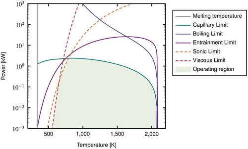
1. Capillary limit: This limit is encountered when the liquid in the evaporator is evaporated at a greater rate than it can be returned to the evaporator due to insufficient capillary-driving pressure compared to the pressure losses around the circuit.
2. Entrainment limit: This limit occurs when the vapor phase is able to shear off liquid from the wick surface into the central channel, thus limiting the flow of liquid to the evaporator.
3. Boiling limit: This limit occurs when nucleate boiling occurs in the evaporator at such a rate that bubble formation and departure inhibit the return of liquid to the evaporator.
4. Viscous limit: This limit occurs when the vapor pressure is insufficient to overcome the pressure drop along the pipe, thus shortening its distance into the condenser region.
5. Sonic limit: This limit occurs when the vapor flow is choked at the evaporator exit due.
Of these five limits, the capillary, boiling, and entrainment limits are considered “catastrophic” heat pipe failures from which normal operation is not recoverable without a reactor shutdown. The remaining two limits are considered “bounding” limits, resulting in decreased heat fluxes at the evaporator and condenser side of the heat pipe. If the temperature were to change to more favorable conditions away from the bounding limits, the heat flux would then return to normal operation, as designated by the shaded region in . Although heat pipes retain a limited ability to transfer heat to the secondary side via conduction through the heat pipe casing, the rate of heat transfer through the steel heat pipe casing is significantly smaller than the heat flux realized by operating heat pipes, so this heat transfer mechanism is typically ignored.
In addition to the five operational limits described previously, the extremely low temperatures of heat pipes are limited by the freezing point of the working fluid, which becomes essential during cold startup or shutdown. Lastly, failures due to casing breaches, which result in the loss of the working fluid, can also result in “catastrophic” failure of the heat pipe.
In general, heat pipes provide a high level of confidence in robustness and reliability due to the lack of moving parts and sealed design. Although the primary risk to a microreactor is loss of heat removal, any modern core design will likely be able to handle failure of one or two heat pipes. Consequently, cascade failure is often considered a primary failure mode that needs to be avoided.
II.B. Code Requirements
The attractiveness of heat pipe microreactors comes from the idea that the core is inherently self-regulating, simplifying the reactor design and requiring fewer safety-related components. The very nature of self-regulation lies in the tight coupling between the neutronic and thermomechanical behavior of the core, thus requiring a multiscale modeling approach to connect different phenomena in computational space. The work presented here focuses on the code coupling to show that DireWolf can be used to show that the core is indeed self-regulating. This requires the combination of fundamentally different codes to simulate the feedback mechanism between heat generation, temperature, thermal expansion, and fluid flow.
A simplistic overview of the coding hierarchy is provided in . In general, the simulation pathway can be separated into two broad families: neutronics and thermomechanics. For each grouping, a “parent” application combines the relevant information from several “children” applications into a single-state variable (e.g., power profile or temperature distribution) and passes back to the other “parent” application. In the MOOSE MultiApp system utilized here, one of the parent applications must be the “master app” from which the simulation starts and finishes. For this specific use case, the reactor physics code is the master app due to the need for a restart capability, as discussed further in Sec. III.B, although, in principle, either parent code could be the master app.
Fig. 2. Overview of coupling architecture for microreactors. As a first step, self-regulation of the core, with the necessary pieces highlighted in yellow, needs to be shown for a given microreactor core design
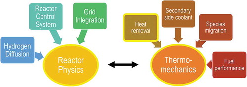
During the genesis of this work, a code downselection was performed that settled on tools based on the MOOSE framework, primarily due to the native coupling built into any MOOSE-based code.Citation14 Since the focus of the work here is on capturing the self-regulation behavior of the core, only a limited set of phenomena are required from the larger code hierarchy, as highlighted in yellow in . Concurrently, an eye toward more complex and long-term phenomena must be maintained so as not to hinder future simulation capabilities. As a result, the larger modeling goals, as detailed in , must be kept in mind while doing any reactor simulation. As with any particular design, the amount of physical phenomena that must be addressed is daunting. Fortunately, the focus on self-regulation behavior allows for a reduced set of problems to be addressed here before moving on to more complex code coupling.
Fig. 3. Expanded code architecture with the required problems to be solved by each code and through what mechanism each code will link. Phenomena not utilized here but in development using a MOOSE-based tool are shown in gray. Codes in circles are outside of the MOOSE framework. Note that the cross-section database may require more dependencies than shown here
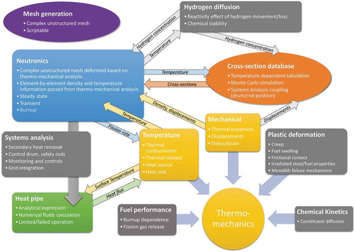
Each box in contains extensive computational methods, models, physics, material properties, and developmental history led by teams of individuals at different organizations. In addition, the linkages between the codes are nontrivial and deserve focused attention to ensure appropriate implementation. The work here does not focus on the individual codes and methods, but rather on the ability of DireWolf and the underlying MOOSE framework to link the necessary pieces. Also, the metrics of success here are limited to the ability to capture self-regulation only. As such, the accuracy of each model will not be assessed quantitatively, and long-term impacts on the core such as creep, hydrogen diffusion, and secondary-side considerations are not addressed here as each of these topics deserves entire studies of their own.
The self-regulation of microreactors is enabled by the rapid reactivity responses to temperature and thermal expansion of the core. In previous coupled simulations by LANL for small space reactors, the core design was simplified such that the swelling of any given component was azimuthally symmetric.Citation15 This symmetry allowed for the combinational geometry mesh traditionally utilized by Monte Carlo neutronics codes like MCNP to be utilized, as any volumetric change in the mesh could be captured by simple dimensional changes (e.g., cylinder radii). As the smaller heat pipe reactors are scaled up to larger terrestrial reactors, symmetric changes in the volume cannot be guaranteed due to heterogeneity of the core into different components (e.g., fuel, moderator, heat pipe) and regions. As a result, an unstructured mesh with element-by-element state variables for temperature and density is necessary to capture the complex geometric changes expected from the microreactor core.
The information passed between the thermomechanics and neutronics codes in this work are (but are not required to be) located on the same mesh. This colocation of variables will allow elemental state variables to be passed without interpolation. The linkage between the thermomechanics code and heat pipe is limited to state variables at the surface of the heat pipe.
II.C. Empire Assessment Problem
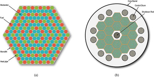
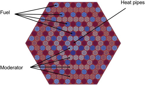
In order to develop the coupling methodology and truly test out the capabilities in DireWolf, a core design was required that was generic enough to avoid any proprietary concerns, while specific enough to capture the primary design characteristics embodied by a heat pipe–cooled microreactor. To that end, the so-called “Empire” core design originally developed at LANL was co-opted to fill the need for a design test bed.Citation16 displays the hexagonal pitch in a layered pattern that defines the general Empire core design. Although not tested here, a 2-MW(thermal) core can be built up from 18 unit assemblies (), with higher power reactors possible by combining more unit assemblies. Control drums in the reflector provide long-term reactivity control, while a shutdown rod in the center of the core provides a means of rapid reactivity control.
Fig. 4. (a) Empire unit assembly and (b) example core design.Citation16
During cross-section generation of the Empire design, it quickly became apparent that the use of yttrium hydride in the simple heterogeneous ring configuration leads to a positive thermal reactivity feedback of the unit assembly, likely due to hydrogen upscattering of thermalized neutrons. Since this assessment problem is meant only as a demonstration of DireWolf, and by no means intended to be the final core design, the Empire design was retained, albeit with a fixed moderator temperature—an assumption that is impossible in the real world but a simple modification in computational space. This model change results in a core with a negative temperature feedback and avoids costly design searches for a genuinely self-regulating core. Once the simulation workflow is demonstrated, these tools can be applied to more realistic core configurations.
Some of the basic core design parameters are provided in . Many of the heat pipe values displayed in are drawn from previous design parameters and experimental measurements.Citation17–20 The material properties used in this analysis, included in , utilize approximate values to provide comparison to any future reference of this core. Note that due to homogenization of the mesh resulting in no-fuel/monolith or moderator/monolith gaps, the Young’s modulus for all materials is set to be a tenth of the monolith strength to prevent overestimation of displacements from fuel swelling or moderator thermal expansion.
TABLE I Empire Design Parameters*
TABLE II Heat Pipe Design Parameters
TABLE III Material Properties*
It is essential to keep in mind the model used here is not entirely realistic, in the sense that the cross sections will not be interpolated using the moderator temperature (due to the aforementioned positive coefficient). Also, since only a single assembly is analyzed here, the neutron leakage mechanical constraint will not be adequately accounted for compared to the full core. Regardless, the design presented here provides an excellent test for which to exercise the code-coupling capabilities in DireWolf.
III. METHODS
Given the code requirements and the overview of the self-regulation simulations for heat pipe–cooled microreactors in Sec. II, the actual code selection and workflow are outlined in Secs. III.A and III.B.
III.A. Code Selection
As mentioned previously, the MOOSE toolset was downselected due to its native ability to link codes to the vast amount of physics being explored by various institutions.Citation14,Citation21 The primary tool utilized was the DireWolf application, which is essentially a collection of various other codes, namely, Bison, Griffin, Sockeye, and RELAP-7 into a single executable. A brief overview of the different codes is discussed for completeness, but the reader is referred to the references in each subsection for in-depth code descriptions.
III.A.1. MOOSE
MOOSE (CitationRef. 7) provides the software infrastructure for developing fully integrated multiphysics modeling and simulation capability. Within MOOSE, the Jacobian-Free Newton Krylov method serves as a parallel nonlinear solution method that naturally supports effective coupling between physics equation systems. Each piece of physics, or “kernel,” contributes to the nonlinear residual which is driven to zero within a convergence criterion. MOOSE provides a comprehensive set of finite element support capabilities via LibMesh integrationCitation22 and provides mesh adaptation and parallel execution. The framework heavily leverages software libraries from the DOE Office of Science and NNSA, such as the nonlinear solver capabilities in the Portable, Extensible Toolkit for Scientific Computation or PETSc project from Argonne National LaboratoryCitation23 (ANL), and Hypre from Lawrence Livermore National Laboratory for advanced multigrid preconditioning.Citation24 In MOOSE, all of the “computer science” pieces required to solve complex nonlinear equations, including parallelization, spatial and temporal discretization, and spatial dimensionality, are hidden from the software user, allowing the developer to focus on the physics and multiphysics coupling algorithms. MOOSE provides a wide variety of physics modules to assist in developing MOOSE-based applications, such as thermomechanics, phase-field operators, multibody contact, multimesh fields, etc.
All DireWolf physics applications follow the MOOSE framework software quality paradigm. This paradigm revolves around a standard set of requirements for all INL MOOSE-based software application development that must be adhered to, including a strict MOOSE coding convention standard, syntax checking, unit tests, verification tests, percentage of code covered by tests, and code documentation (e.g., theory and user’s manuals, software requirements, and software management plans, etc.). As a result of these requirements and additional Nuclear Quality Assurance-1 (NQA-1) documentation requirements, MOOSE is recognized as NQA-1 compliant. In order to maintain compliance, the Bison nuclear fuel performance code and the MOOSE framework have undergone external assessment at a higher rigor of independent assessment.Citation25 Both the MOOSE framework and the Bison nuclear fuel performance codes meet the rigorous software quality assurance (SQA) requirements of NQA-1, resulting in their certification for use in nuclear safety software applications.
The advantage of following identical software development practices for MOOSE-based software is that, in reality, all NEAMS MOOSE-based software applications are part of the same “code.” Thus, the coupling of DireWolf’s physics applications for multiphysics simulations is a straightforward process using built-in MOOSE MultiApp and Transfer systems. These MOOSE systems give DireWolf the flexibility to run both tightly coupled and loosely coupled simulations among MOOSE-based applications. The MultiApp system handles the creation, spatial positioning, and execution control of multiple applications coupled to build up more complex multiphysics simulation models from existing applications.
III.A.2. Griffin
Griffin is a MOOSE-based neutronics application designed for the analysis of advanced reactors that is jointly owned by INL and ANL, with its development based on the MOOSE SQA procedures. It consists of the merger of two suites of codes: Rattlesnake + MAMMOTH developed at INL and MC2-3 + PROTEUS developed at ANL. Although many of the multiphysics applications using the current capabilities of Griffin are further detailed in CitationRef. 26, a brief overview of the codes is provided here for completeness.
Rattlesnake is a MOOSE-based multiphysics, multischeme radiation transport application.Citation26 It can model various neutral particles, such as neutrons, photons, and phonons in eigenvalue, steady-state, and transient simulations. It offers several schemes to solve the multigroup transport equation, including diffusion and spherical harmonics and discrete ordinates (SN) methods, with both continuous and discontinuous finite element methods (FEMs). It also allows different discretizations to be used in other parts of the domain.Citation27 Also of particular interest to the analysis of microreactor transients with control rod/drum rotation is the projection-based cusping treatment to improve the behavior when the tip of the rod/drum does not align with the mesh.Citation28 MAMMOTH is also based on the MOOSE framework, was designed as a reactor physics tool, and provides additional features to the analyst such as macro- and microdepletion capabilities. ANSI/ANS-5.1–2005 standard decay heat curves are also supported. In addition, it supports full-core homogenization equivalence techniques in order to preserve reference quantities of interest, such as multiplication factor and reaction rates, while using coarsely homogenized geometries.Citation29,Citation30
MC2-3 is a FORTRAN multigroup cross-section generation code for fast reactor analysis, relying on advanced resonance self-shielding and spectrum calculation methods.Citation31 PROTEUS is a FORTRAN neutron transport code offering different solving strategies, including nodal, SN, and the method of characteristics (MOC), which combines a two-dimensional (2-D) MOC with the discontinuous Galerkin FEM for the axial direction.Citation32 The capabilities present in PROTEUS and previously missing from Rattlesnake + MAMMOTH are currently being migrated into Griffin.Citation33
III.A.3. Sockeye
Sockeye is a joint INL and LANL heat pipe analysis program built on top of the MOOSE framework.Citation34 As a MOOSE-based application, Sockeye readily couples to MOOSE for thermal mechanics and the greater simulation framework of Bison, Griffin, and RELAP-7. Sockeye has been prototyped, demonstrated, and benchmarked against a legacy LANL heat pipe code employing simplified models that has also been tightly coupled to the Bison nuclear fuels performance application using a hexagonal-shaped metal fuel proof of concept.Citation35
Sockeye features two main modeling options: a one-dimensional (1-D), two-phase, high-fidelity flow model coupled to 2-D–RZ (axisymmetric) heat conduction in the heat pipe wall, and a simplified 2-D–RZ effective heat conduction model ().
Fig. 5. Illustration of Sockeye modeling options showing (b) a heat pipe schematic, (a) the 1-D flow model coupled to 2-D–RZ heat conduction, and (c) 2-D–RZ effective heat conduction model. The arrows indicate the direction of flux coupling
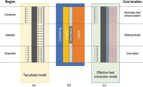
The 1-D flow model is based on the 7-equation model, a well-posed, nonequilibrium, compressible model of two-phase flow.Citation36,Citation37 Modifications were made to the 7-equation model to include capillary pressure due to the wick and closures specialized for a heat pipe.
The effective heat conduction model treats the entire heat pipe (vapor core, liquid/wick/annulus, and wall) as a 2-D–RZ region of heat conduction. Approximating the creeping flow justifies the liquid and vapor region by a standard heat conduction of the liquidCitation38 and the use of a very high thermal conductivity in the vapor region to approximate the fast vapor flow transporting heat via latent heat. A thermal resistance analysis can be used to derive effective thermal conductivities for various heat flow paths in the heat pipe. This analysis shows that the thermal resistance through the liquid-vapor interface is minimal. Thus the axial thermal resistance through the vapor core can be approximated using an analytic pressure drop coupled with the assumption of saturation of the vapor phase and the Clausius-Clapeyron equation.Citation12 The analysis shows that this thermal resistance is minimal,Citation12 and thus the equivalent thermal conductivity is very high. Thermal resistances are dominated by radial conduction in the wall and wick regions.
Sockeye also can employ analytic relations for operational heat pipe limits, as discussed in Sec. II.A. These expressions are derived using several assumptions and approximations and take the form of a maximum heat transfer rate for a given temperature: (CitationRef. 12). Sockeye has implemented relations for the capillary, sonic, viscous, entrainment, and boiling limits. During a simulation, these can limit the heat rate into or out of a heat pipe by rescaling the heat flux. Since the two-phase flow model seeks to model these limits numerically in a transient fashion, this feature is used primarily for the effective heat conduction model. It has no other mechanism to predict heat pipe limits. A temperature value
is utilized, typically taken to be the average temperature of the core region of the heat pipe. Each limit is evaluated at this temperature, and the maximum value power is calculated:
Then the boundary flux imposed on either the evaporator or condenser end, , is scaled to enforce the minimum limit, where
is the scaled boundary flux:
where is the surface area corresponding to the chosen end (evaporator or condenser), and
is the corresponding sign (+1 for evaporator, −1 for condenser). Additionally, if the minimum limit corresponds to a “catastrophic” limit, for which dryout is the anticipated result, the power on the chosen end is set to zero for the remainder of the transient, i.e.,
.
III.A.4. Bison
Bison is a finite element–based nuclear fuel performance code applicable to various fuel forms, including light water reactor fuels, TRISO particle fuel, and metallic rod and plate fuels.Citation39 Bison solves the fully coupled equations of thermomechanics and species diffusion for either 2-D axisymmetric or three-dimensional (3-D) geometries. Included are fuel performance models to describe temperature- and burnup-dependent thermal properties, fission product swelling, densification, thermal and irradiation creep, fracture, and fission gas production and release.Citation40–42 Also implemented are plasticity, irradiation growth, and thermal and irradiation creep models for clad materials. Models are also available to simulate gap heat transfer, mechanical contact, and the evolution of the gap/plenum pressure with plenum volume, gas temperature, and fission gas addition. Bison is based on the MOOSE framework and can efficiently solve problems using standard workstations up to large leadership-class computers.Citation43 Bison’s validation is an ongoing process and is continuously conducted against a wide variety of integral fuel rod experiments.Citation44
III.A.5. Serpent2
Serpent2 is a Monte Carlo continuous-energy particle transport code developed at the VTT Technical Research Centre of Finland, Ltd since 2004 (CitationRef. 45). Similar to MCNP, Serpent2 has been utilized in nuclear reactor core, multiphysics coupling, and neutron source dose rate calculations. Serpent2 has been used in the past for coupled multiphysics simulations, including for cross-section generation for Rattlesnake simulations.Citation46,Citation47
III.A.6. Mesh Generation
Whenever possible, the meshing capabilities built into MOOSE should be and are utilized to generate unstructured meshes in an easily modifiable format. Here, MOOSE was used for the mesh formulation required by Sockeye, which consists of a 2-D–RZ heat structure coupled to a 1-D fluid flow. Unfortunately, the mesh required by the core geometry is too complicated for the built-in tools. Thus, CUBIT (CitationRef. 48) was used to generate an exodus-formatted mesh file for use in Bison and Griffin, the details of which are described in Sec. III.B.2.
III.B. Workflow
The general methodology used in this work follows several steps. First, homogenized macroscopic cross sections are generated within the Monte Carlo code Serpent2 (CitationRef. 49), with their dependency with respect to displacement and fuel temperatures studied in Sec. III.B.1. Macroscopic cross-section data generated by Serpent2 are converted to the required Griffin XML format using the ISOXML package, which is included in the Griffin repository.Citation26 These cross sections are then utilized in a coupled Griffin, Bison, and Sockeye simulation using DireWolf as a driver to provide an initial steady-state reactor condition. Finally, transients are initiated by “restarting” from the steady-state behavior with some perturbation in power or heat pipe operation.
III.B.1. Cross-Section Generation
The cross sections for the model used here were generated using a 3-D heterogeneous assembly Serpent2 model without gaps between the monolith and the fuel, moderator, and heat pipes. One-centimeter-thick SS316 reflectors on the top and bottom of the core are utilized, along with vacuum boundary conditions axially and reflective boundary conditions radially.
A tabulation of homogenized cross sections is prepared in 15 energy groups derived from the ECCO 33-group structure for the four following materials: (1) fuel, (2) moderator, (3) heat pipe, and (4) monolith region for cm (which corresponds to the fuel region).
Three reactivity feedback mechanisms are considered: (1) fuel temperature, (2) moderator temperature, and (3) displacement due to thermal expansion. For each of these, an appropriate tabulation covering the expected physical ranges during the transient would ideally be adopted and the Serpent2 model would be run for each of the combinations, thereby creating a tabulation library.
In order to capture the cross-section changes due to temperature, a grid of fuel temperatures was utilized to capture the expected temperature range of the fuel. Macroscopic cross sections were calculated for fuel temperatures from 400 to 1400 K in 100-K increments. A formal study on temperature increments will be necessary in order to confirm the accuracy of such a temperature grid if quantitative comparison is available. Using the tabulated Serpent2 calculations, a fuel temperature reactivity coefficient on the order of −1 pcm/K was obtained.
As discussed in Sec. II.C, it was observed that the YH moderator in the Empire core configuration leads to a high positive temperature reactivity coefficient on the order of 5 pcm/K, resulting in a net positive temperature reactivity coefficient for the core. Although
for YH
has recently been implemented in the recent ENDF/B-VIII cross-section library, a continuous-energy
treatment has not been integrated into Serpent2 at this time. Consequently, Serpent2 is unable to read the
data format used in MCNP libraries. However, testing using MCNP with the
for YH
has shown similar temperature reactivity coefficient values. For the purpose of this study, the temperature of YH
was thus fixed to a constant temperature of 300 K to obtain a self-stabilizing behavior to simulate self-regulation. Therefore, no tabulation with respect to moderator temperature was considered.
Cross-section evaluations with respect to the temperature of the monolith were omitted in the present study. While it is expected that the temperature dependency impact will be minor on the assembly-wide parameters, this assumption needs to be justified via a formal analysis of the impact of temperature on the cross sections of the materials that comprise the monolith.
Although the impact of temperature on the microscopic cross sections is captured via Monte Carlo Serpent2 simulations, the impact of thermal expansion affects the macroscopic cross section from changes to (1) the fuel pitch and (2) density. While the former is problem dependent and must be calculated using uniquely dimensioned Serpent2 geometries, the latter linearly affects the macroscopic cross section. Fortunately, density changes can be easily captured in Griffin simulations on the fly. In contrast, the impact of geometric displacement (i.e., pitch changes) as a function of temperature needs to be estimated to ensure the correct physics is captured. Assuming the fuel remains centered in the hole of the monolith, the fuel pitch will be controlled by the thermal expansion of the stainless steel monolith. Taking a conservative change in temperature of 400 K in the monolith and an estimated thermal expansion coefficient of 1.3
L/L per K, the fuel pitch will increase by about a half a percent. Such a small change in fuel pitch will likely result in an immeasurable difference in reactivity. In addition, simple Serpent2 tests, including the effects of density and geometric displacement changes, confirmed that the change in fuel pitch results in a reactivity change that is overshadowed by the changes in density. Although not accounted for here, further quantification of the impact of thermal expansion on the reactivity needs to be performed using a full 3-D core before geometric changes can be ignored for any given design.
While the effect of geometric displacement has been omitted in the calculations reported here, similar analyses must be performed for more extensive core-level calculations to ensure the assumptions still hold.
III.B.2. Mesh
Separately from the cross-section generation model, a finite element unstructured mesh needs to be created for the thermomechanical and neutronics-coupled simulations. If the models are simple (e.g., cubes, cylinders, spheres) they can be created using the MOOSE built-in meshing tools via the input file. Otherwise, the meshes need to be built using external software. Since MOOSE codes natively work on meshes with the exodus format, CUBIT was used to generate the 2-D assembly unstructured mesh. The same mesh was utilized for the Griffin and Bison simulations, as presented in , and consists of an entire 2-D assembly without gaps and with a total of 15 724 elements.
Fig. 6. Two-dimensional assembly mesh
III.B.3. Finite Element Models
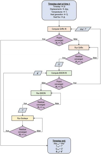
A steady-state thermomechanical-neutronics calculation is used as an initial condition for the transient using the problem-specific cross sections and generated unstructured mesh analysis. This multiphysics problem is solved in a tightly coupled manner, i.e., using Picard iterations to solve each physics in turn until convergence is achieved. An overview of the code execution is provided in . The main advantage in doing so, compared to a fully coupled approach where all the physics are solved simultaneously in a single nonlinear system, lies in the simplicity of the coupling using MOOSE-based codes, as well as the freedom to tailor the numerical discretization to each physics and to avoid the intricacies of scaling the various variables. Practically, it was observed that converging Picard iterations with “steady-state” solves could yield numerically unstable methods for complicated multiphysics problems.Citation50 Rather, a so-called “pseudo transient” is run to establish the steady-state solution. This consists of introducing a time-derivative term in the steady-state equations and solving until the variations in the solution between two consecutive time steps become negligible.
Fig. 7. Flowchart of the linkage between the Griffin, Bison, and Sockeye calculations in DireWolf for the transient calculations. The decision points (purple diamonds) correspond to convergence criteria checking based on the residual R to either the Picard iteration tolerance or the internal application convergence criteria
. The “
” notation here signifies intermediate calculated variable values. Note that it is possible for “children” applications to have smaller time steps than the “parent” applications, but this is not visualized here. Also, the eigenvalue calculation is slightly different due to pseudo-transient calculation performed by Bison, however, the general linkage is similar
Finally, a transient problem is run using the same cross sections and mesh with the steady-state solution as the initial condition. The eigenvalue computed during the steady-state simulation is used to scale the fission source so as to preserve a perfectly critical core as an initial condition for the transient simulation. The reactor condition can be changed to trigger a transient response during the first time step of the transient simulation (e.g., change in power in the heat pipe condenser region) at predetermined times (e.g., load following) or as a conditional on the state of the reactor (e.g., heat pipe failure).
The Griffin input imposes vacuum boundaries for the scalar flux on all radial sides, with reflective boundary conditions assumed in the axial direction due to the 2-D geometry. While far from realistic due to adjacent assemblies or radial shields present in a full core as well as being inconsistent with the reflecting boundary conditions used in the Serpent2 model, the vacuum boundary conditions were chosen here to confirm that allowing displacement and leakage in more than one dimension will result in a negative thermal expansion feedback. For simplicity, a continuous FEM diffusion scheme is used. Assuming the power of the full core is 2 MW(thermal) with this unit assembly representing one of the 18 assemblies, the assembly power should be about 111 kW. Since the height of the fuel region is 60 cm, the initial linear power in the unit assembly is set to 185 kW/m.
The Bison model utilizes heat condition and finite elastic strain models along with two different displacement boundary conditions on the outer surface of the assembly to try and bracket the behavior of a realistic core constraint. By fixing the x and y displacements along the outer region of the 2-D unit assembly, a fully constrained assembly can be simulated. Extrapolating to a full-core design, this represents a fully constraining core barrel that suffers no thermal expansion. In reality, the core barrel and all core internals will have a nontrivial amount of 3-D displacement. To estimate the impact of the core barrel constraint while avoiding modeling the entire reactor core here, a second bounding simulation was run in which the unit assembly was constrained in the y direction using the two bottom corners of the hexagon and in the x direction using the left-bottom corner. This pinned geometry allows the assembly to displace freely along the hexagon boundaries. Again, this model is not fully representative of a given assembly in a reactor since the adjacent assemblies will provide some resistance to free expansion. Still, it provides a bounding case for mechanical feedback. Unless otherwise specified, all models will be based on the unconstrained assumption.
For the temperature field, Bison utilizes a convective heat flux on all sides of the core using a convective heat transfer coefficient of 30 W/K/m and a far-field temperature that linearly changes from 680 to 720 K from the bottom-left to the top-right hexagon flat. Although somewhat arbitrary, this boundary condition aims to reproduce potential behavior between assemblies separated by an air gap while providing prototypical temperatures of the core during the simulation.
Finally, a heat flux boundary condition is applied on the inner surface of the monolith at each heat pipe hole. The value of the heat flux is transferred from the Sockeye solution and corrected for the 2-D–RZ to the 2-D transformation.
III.B.4. Heat Pipe Model
As discussed in Sec. III.A.3, Sockeye is able to run both a full-fluid or an approximate high-conductivity solid diffusion problem. In general, the full-fluid solution is unnecessarily complicated in most core design simulations, especially far from any startup/shutdown transients or failure limits. However, the ability to easily switch between models enables agile design space exploration with the simpler model and switching to the two-phase model where required.
The workflow adopted here utilized the effective heat conduction Sockeye model informed by the two-phase model. In particular, the two-phase Sockeye simulation was run at a variety of evaporator wall temperatures and heat flux boundary conditions to determine net power and internal temperatures. The effective heat conduction model was created with the same geometry, and the thermal conductance of the core was modified—here, determined to be 2 W/m/K—to match the power and average internal temperatures within 0.1%. Finally, the coupled unit assembly simulations were run with the effective heat conduction model. By leveraging the advantages of both models, the robustness and speed of the effective heat conduction model could support the full-assembly simulations, while still maintaining a high level of accuracy through informed model design via high-fidelity Sockeye simulations. Although the two-phase simulations could more accurately capture the operating limits, the use of analytical limits here allows for rapid design prototyping and provides insight into the core behavior before moving on to more complex models.
During any given Sockeye simulation of the 61 rods present in the unit assembly, comparisons are made to the analytical limits described in Secs. II.A and III.A.3 to adjust pipe operation accordingly.
At the evaporator end of the heat pipe, a convective heat flux boundary condition is applied that uses the average monolith temperature of each heat pipe hole, as transferred from Bison, and an arbitrarily large heat transfer coefficient to model efficient heat transfer between the monolith and heat pipe casing ensuring global energy conservation. As the Bison model is refined to include contact algorithms, a formal investigation to determine an appropriate heat transfer coefficient is warranted. On the condenser end of the heat pipe, a Neumann boundary condition is used with a heat flux set as an input. For now, this input heat flux is the total power of the core divided by the heat pipes in the total core. Once RELAP-7 is fully coupled, the heat flux at the condenser side will be more refined to capture realistic heat removal systems.
IV. RESULTS
Following the model development and workflow described in Sec. III, a series of simulations were performed to test the ability of DireWolf to capture the self-regulation behavior on the testbed Empire core in Secs. IV.A, IV.B, and IB.C. Due to the geometric and cross-section assumptions adopted for this work, the results that follow serve to exhibit the capabilities within DireWolf. Although self-regulation, or more explicitly, coupling between temperature and reactor power, has been demonstrated for the reduced model here, this does not necessarily translate to realistic full-core behavior
IV.A. Steady-State Simulation
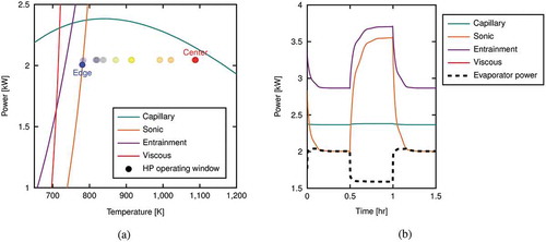
As discussed in Sec. III.B.3, a steady-state simulation is required as an initial condition for all transient simulations. shows some of the most important parameters calculated by DireWolf, including the fluxes of the most thermal and the fastest neutron energies, the temperature, and the power density. In addition to parameters calculated by Griffin and Bison, the operating values of the heat pipes as calculated by Sockeye are provided in and show that all heat pipes are operating within the boundaries of the normal operational envelope. The highlighted “center” and “edge” circles indicate that the heat pipe at the center of the assembly is close to the capillary limit. In contrast, the heat pipe at the outer edge of the assembly (farthest left in ) is closest to the sonic limit.
Fig. 8. Results from the steady-state solution [i.e., 2-MW(thermal) reactor] showing (a) the fastest and slowest neutron energy fluxes, power density, and temperature, and (b) the analytical limits for the Sockeye heat pipe design used here compared to the operating profiles of the 61 heat pipes in the unit assembly. The power applied to the condenser side of each individual heat pipe for the different reactor powers [here, 2.0, 2.1, and 2.2 MW(thermal) for the total core power, not the power draw of the individual heat pipes] are shown as vertical lines
![Fig. 8. Results from the steady-state solution [i.e., 2-MW(thermal) reactor] showing (a) the fastest and slowest neutron energy fluxes, power density, and temperature, and (b) the analytical limits for the Sockeye heat pipe design used here compared to the operating profiles of the 61 heat pipes in the unit assembly. The power applied to the condenser side of each individual heat pipe for the different reactor powers [here, 2.0, 2.1, and 2.2 MW(thermal) for the total core power, not the power draw of the individual heat pipes] are shown as vertical lines](/cms/asset/a6ba15e6-29d9-4740-80e7-a7b48568fc09/unct_a_1906474_f0008_c.jpg)
Although the subsequent transient results focus on the change in fuel temperatures, the relative swings in temperature can be applied to other components in the core, given knowledge of the steady-state temperatures, to approximate the temperatures of the moderator, heat pipes, and monolith. To that end, the peak, average, and minimum temperatures of different components are profiled in .
TABLE IV Initial Temperatures of the Different Components in the Unit Assembly Before Any Transient Conditions Are Applied*
IV.B. Power Oscillation
In order to thoroughly test the core’s ability to self-regulate, the first transient to be explored was changes in total power draw on the heat pipe condenser. Restarting from the steady-state DireWolf solve, the temperature was first increased to 115% of the nominal power, decreased to 85%, and increased back to 115%, in increments of half-hours. This is indicated by the gray line in . Focusing first on the initial increased power draw at the beginning of the transient, the increased power at the condenser side of the heat pipe results in a corresponding heat flux increase at the heat pipe evaporator (), and an eventual decrease in average fuel temperature (). The decrease in fuel temperature results in a positive reactivity insertion and subsequent power rise, which overshoots the 115% power draw. This in turn results in the heat up of the fuel and negative reactivity insertion, lowering the net assembly power. Eventually, the power and temperature oscillations are dampened until the 115% power draw is reached, as set by the condenser side of the heat pipes. The tight coupling between the power and fuel temperature is visible by matching the peaks in each value in . Although each self-regulation transient may be different, these same principles will apply for all transients (i.e., interplay between fuel temperature, reactivity, and power).
Fig. 9. Evolution of the heat pipe power, assembly power, and fuel temperature as a consequence of the transient. Note, the heat in (a) is given in absolute value
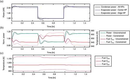
As with self-regulated cores in general, the average temperature of the fuel at the beginning and end of the transients are relatively the same, while the temperature gradient throughout the core increases with increasing power (). Note that small changes in the average fuel temperature are partly a consequence of the nonlinearity of the tabulated cross sections, along with potential shifts in flux profiles and changes in the temperatures of surrounding components.
Included in are the power and fuel temperature for an unconstrained assembly, as well as a fully constrained assembly (translucent lines). As discussed in Sec. III.B.3, the treatment of displacements has a major impact on the period and amplitude of the power and fuel temperature transient behavior. For assemblies that are fully constrained, self-regulation must rely more explicitly on the impact of fuel temperature on the cross sections to provide the necessary changes in reactivity, as evidenced by the lower average temperature required to reproduce the same 115% power draw when the assembly is fully constrained.
In addition, the magnitude of the power shift impacts the amplitude in the power and fuel temperature oscillations. By comparing the first power jump from 100% to 115% nominal power to the second jump at 1.0 h from 85% to 115%, the amplitude is much higher for both the average fuel temperatures and total assembly power. These power jumps indicate that DireWolf may play a valuable role in determining operational limits on power transients to prevent extreme power and temperature swings.
Similar to , the operating conditions at the end of the power oscillation transient (i.e., at 115% power) can be used to see how far away the heat pipes are from the operating limits, as plotted in . In general, as with the fuel temperature gradient, the heat pipes in this particular core design will also suffer from an increase in temperature gradient as the power increases. Consequently, the center heat pipe is closer to the capillary limit at the end of the transient due to an increased peak heat pipe temperature (which moves the point to the right), as well as an increase in power per heat pipe (which moves the point up). If power were increased much further, the center heat pipes might eventually reach the capillary limit, resulting in a catastrophic failure.
Fig. 10. Power draw at the evaporator side of the heat pipes at the end of the power transient compared to the operating limits for (a) all heat pipes in relation to the analytical limits as a function of temperature, and (b) as a function of time for the heat pipe on the farthest left edge of the assembly. Note, in (a), the operational space for the center and edge heat pipe bracket the operational limit extremes in blue and red, respectively
At the end of the transient, the cooler heat pipes at the outermost corners of the unit assembly hex are limited by the bounding sonic limit, thus limiting the total energy removed by the heat pipes and generated by the assembly. This behavior is visible by tracing the individual limits and evaporator power calculated by the left-most edge heat pipe, as in . During the initial and final 115% power transients, the power draw at the evaporator side of the edge heat pipe follows the sonic limit. Once the power draw is reduced to 85%, the heat pipe temperature in the edge heat pipe increases, moving the evaporator power far away from the analytical limits. It is clear that from these simulations that DireWolf can naturally handle such bounding limits on heat pipe operation, which can be leveraged in more complex full assembly simulations.
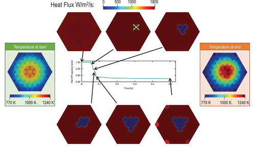
IV.C. Cascading Heat Pipe Failure
In addition to the transient behavior in which the heat pipes remain within the normal operations envelop, transients that push the assembly to catastrophic limits can be simulated to estimate the core behavior as heat pipes start to fail. Moreover, one of the anticipated accident scenarios for heat pipe–cooled microreactors is a cascade failure of heat pipes initiated by a failure of a heat pipe as a consequence of loss of working fluid due to gross mechanical failure or manufacturing defects.Citation17 To illustrate the ability of DireWolf to capture such a transient, an overpower transient at 19% was simulated with and without a manual “failure” of a heat pipe between the center and the edge of the assembly.
Such a cascading heat pipe transient can be explained by looking at the net heat pipe capacity factor, which represents the ability of the entire assembly to remove the heat asked of it at a given time. For the transient run here, a plot of the heat pipe capacity factor is given in the center of , and shows the stepwise function of failing heat pipes as a function of time. At each step decrease of the net capacity factor, a corresponding visualization of the power in the assembly is provided in , starting with the initial damage failure at 0.05 h, designated by the “” in the top image in . As the transient continues, several other heat pipes begin to fail due to hitting the catastrophic capillary limit, until finally stabilizing at 0.8 h. For the remainder of the transient, the net capacity factor falls slightly due to the heat pipes on the outer edges of the assembly being bound by the sonic limit, which is visualized in the bottom-right assembly picture in . As a consequence of the heat pipe failures, the temperatures in the right-of-center region of the assembly are significantly higher at the end of the transient.
Fig. 11. Progression of cascade failure during a 19% power transient. The first heat pipe failure at 0.05 h, designated by the yellow “,” kicks off a series of failures in surrounding heat pipes that would otherwise not occur
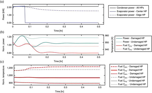
Following the description of the cascade failure in , the heat pipe fluxes, assembly power, and fuel temperatures can be analyzed in to understand the performance of the assembly during the transient. The increase in power, along with the hard failure of the original heat pipe at 0.05 h, results in the catastrophic failure of the center rod (among others), as seen in . The heat up of the assembly due to the failing heat pipes leads to a decrease in overall power, as seen in . Interestingly, the total assembly power stabilizes at a final power very close to the initial power. However, the maximum fuel temperatures are much higher than in the center of the assembly due to the loss of cooling by the catastrophically failed heat pipes, as evident in . Such drastic fuel temperatures and power shifts could be compared to the expected behavior of the core if the original heat pipe that initialed the cascade failures remained “undamaged,” shown in translucent plots in . Again, although the transient results in nearly the same assembly power, the drastic temperature gradients may be undesirable for long-term operation.
Fig. 12. Evolution of the heat pipe power draw, assembly power, and fuel temperature as a consequence of the transient. Note, the power signs are ignored in order to ease plotting
V. DISCUSSION AND CONCLUSIONS
Self-regulation is the cornerstone of the design and safety analysis for microreactors, likely requiring extensive testing and simulation to ensure the coupling between the thermomechanical-neutronics physics performs as expected. This current work outlines the workflow and results from simulations of a testbed microreactor assembly using the MOOSE-based code DireWolf. The goal of the assessment problem definition is to adequately exercise the MOOSE toolset in order to gain confidence in the ability to simulate self-regulation in a moderated heat pipe–cooled microreactor. To that end, some simplifications were applied to focus the analysis on the coupling of thermomechanical-neutronics physics.
Coupled simulations of thermomechanical analysis using Bison, neutronics analysis using Griffin, and heat pipe analysis using Sockeye, a 2-D unit assembly representative of a heat pipe–cooled microreactor model successfully exhibited physics coupling for several steady-state and transient conditions. Such communication between phenomenon, which in practice, equates to communication between codes, is required to demonstrate self-regulation behavior when applied to a full 3-D core. Cross-section evaluations were calculated using Serpent2 and tabulated as a function of fuel temperature. Several different transient cases were run by either changing the power draw on the condenser side of the heat pipe, or by “failing” a heat pipe during an overpower transient, resulting in cascading heat pipe failure. The code-coupling infrastructure built into all MOOSE framework codes allowed for rapid and straightforward analysis. A suite of simulation results was achievable via simple input file changes with runs on local machines or high-performance computing clusters. In each of the tests, self-regulation was shown to occur due to tightly coupled thermomechanical-neutronics physics via Picard iterations between Griffin, Bison, and Sockeye.
Verification and validation (V&V) of numerical methods and physical models in advanced modeling and simulation are part of best practices in software development and software quality. These steps are necessary so that vendors employing the software for design and safety applications have confidence in the validity of computational results and are generally required by the regulators. The key to developing a useful advanced modeling and simulation capability for a given physical system is a rigorous validation paradigm primarily founded in integrating advanced modeling and simulation development with a stringent multiscale, multiphysics experimental program that is repeatable and delivers data with quantifiable uncertainties.
The traditional methodsCitation51 used in the V&V of single physics software applications have been satisfactorily used for several decades. However, there is still the question of how to apply V&V methodology to multiphysics software and how to resolve interdependencies between particular physics. Each physics application’s verification should be identical whether the physics applications are tightly coupled or not. However, for verification of coupled applications, mathematical and numerical consistency is required between the various spatial and temporal discretization approaches between the physics models. This consistency issue has always presented a challenge.
For DireWolf, verification is straightforward as all the MOOSE-based applications in DireWolf follow the MOOSE NQA-1 software quality paradigm for verification procedures.Citation52 However, the validation of DireWolf is not so simple. For example, it is unclear if DireWolf can be considered “validated” if Bison and Griffin are independently validated against separate experiments and benchmarks. For now, our approach is to validate the DireWolf application against the limited microreactor experimental data as a single physics application in future work.
Through the exercises outlined here, the performance of the MOOSE-based tools show great promise in capturing the self-regulating behavior of a microreactor core. Despite the successes so far, there are many more challenges for the MOOSE-based tools, or any other toolset used to model microreactors. Numerical stability once contact is introduced has yet to be proven in a large core analysis using the MOOSE toolset. Also, coupling to more physics (e.g., secondary-side flow models) needs to be performed to fully analyze a given core design. However, the coupling framework already shown in the present work can be easily replicated to tools such as RELAP-7. Finally, a full-core analysis will push the boundaries of high-performance computing abilities. Regardless, it is clear that the coupling methodology implemented in MOOSE will provide a platform that can allow simulations to start from a tightly coupled physics solution position while attacking the other problems at hand.
Acknowledgments
This work was primarily supported by the Modeling-Enhanced Innovations Trailblazing Nuclear Energy Reinvigoration program for Advanced Research Projects Agency-Energy of the DOE, and by the DOE Office of Nuclear Energy’s NEAMS program.
LANL, an affirmative action/equal opportunity employer, is operated by Triad National Security LLC, for the National Nuclear Security Administration of the DOE under contract number 89233218CNA000001.
INL is a contractor of the U.S. government under contract number DEAC07-05ID14517. Accordingly, the U.S. government retains a nonexclusive, royalty-free license to publish or reproduce the published form of this contribution, or to allow others to do so, for U.S. government purposes.
References
- R. A. JOHNSON, W. T. MORGAN, and S. R. ROCKLIN, “SNAP 10A, First Reactor in Space,” presented at the Aeronautics and Space Engineering and Manufacturing Mtg. (SAE International), No. 650793, Warrendale, Pennsylvania (1965); https://doi.org/10.4271/650793.
- P. R. McCLURE et al., “Kilopower Project: The KRUSTY Fission Power Experiment and Potential Missions,” Nucl. Technol., 206, S1, S1 (2020); https://doi.org/10.1080/00295450.2020.1722554.
- D. I. POSTON et al., “Results of the KRUSTY Nuclear System Test,” Nucl. Technol., 206, S1, S89 (2020); https://doi.org/10.1080/00295450.2020.1730673.
- “GAIN-EPRI-NEI Microreactor Program Virtual Workshop,” Idaho National Laboratory, August 18–19, 2020.
- “Cost Competitiveness of Micro-Reactors for Remote Markets,” Nuclear Energy Institute (2019).
- C. R. STANEK, “Overview of DOE-NE NEAMS Program,” LA-UR-19-22247, Los Alamos National Laboratory (2019).
- C. J. PERMANN et al., “MOOSE: Enabling Massively Parallel Multiphysics Simulation,” SoftwareX, 11, 100430 (2020); https://doi.org/10.1016/j.softx.2020.100430.
- R. S. REID, M. A. MERRIGAN, and J. T. SENA, “Review of Liquid Metal Heat Pipe Work at Los Alamos,” Proc. 8th Symp. Space Nuclear Power Systems, p. 999, American Institute of Physics (1991); https://doi.org/10.1063/1.40058.
- P. McCLURE et al., “Design of Megawatt Power Level Heat Pipe Reactors,” LA-UR-15-28840, Los Alamos National Laboratory (2015).
- D. I. POSTON et al., “KRUSTY Reactor Design,” Nucl. Technol., 206, S1, S13 (2020); https://doi.org/10.1080/00295450.2020.1725382.
- J. W. STERBENTZ et al., “Special Purpose Nuclear Reactor (5 MW) for Reliable Power at Remote Sites Assessment Report,” Idaho National Laboratory (2017).
- A. FAGHRI, Heat Pipe Science and Technology, Global Digital Press (1995).
- D. REAY, R. McGLEN, and P. KEW, Heat Pipes: Theory, Design and Applications, Butterworth-Heinemann (2013).
- C. MATTHEWS et al., “Task 1: Evaluation of M&S tools forMicro-Reactor Concepts,” LA-UR-19-22263, Los Alamos National Laboratory (2019).
- D. I. POSTON, “KRUSTY Design and Modeling,” LA-UR-16-28377, Los Alamos National Laboratory (2016).
- A. J. FALLGREN, D. V. RAO, and H. TRELLUE, “Heatpipe Reactor Design for Special Purpose Applications,” Los Alamos National Laboratory (2018).
- J. W. STERBENTZ et al., “Preliminary Assessment of Two Alternative Core Design Concepts for the Special Purpose Reactor,” INL/EXT-17-43212, Idaho National Laboratory (2018).
- P. J. RING, E. D. SAYRE, and J. T. SENA, “SAFE-100 Module Fabrication and Test,” presented at the Space Technology and Applications International Forum, pp. 96–100, American Institute of Physics (2003); https://doi.org/10.1063/1.1541282.
- B. HOLLEY and A. FAGHRI, “Permeability and Effective Pore Radius Measurements for Heat Pipe and Fuel Cell Applications,” Applied Thermal Engineering, 26, 4, 448 (2006); https://doi.org/10.1016/j.applthermaleng.2005.05.023.
- R. S. REID, J. T. SENA, and A. L. MARTINEZ, “Sodium Heat Pipe Module Test for the SAFE-30 Reactor Prototype,” presented at the Space Technology and Applications International Forum, pp. 869–874, American Institute of Physics (2001); https://doi.org/10.1063/1.1358021.
- C. MATTHEWS et al., “Evaluation of the MOOSE Tool-Set for Analysis of Thermo-Mechanical-Neutronics Coupling in Micro-Reactors,” LA-UR-19-31443, Los Alamos National Laboratory (2019).
- B. S. KIRK et al., “LibMesh: A C++ Library for Parallel Adaptive Mesh Refinement/Coarsening Simulations,” Eng. Comput., 22, 3–4, 237 (2006); https://doi.org/10.1007/s00366-006-0049-3.
- S. BALAY et al., “PETSc Users Manual,” Argonne National Laboratory, ANL-95/11, Revision 3.15 (2021); https://www.mcs.anl.gov/petsc.
- R. D. FALGOUT and U. M. YANG, “Hypre: A Library of High Performance Preconditioners,” Computational Science—ICCS 2002, P. M. A. SLOOT et al., Eds., pp. 632–642, Springer Berlin Heidelberg, Berlin, Heidelberg (2002).
- “MOOSE Framework and BISON Software Application Independent Assessment Report,” ASMT-2020-0436, Idaho National Laboratory (2020).
- Y. WANG et al., “Rattlesnake: A MOOSE-Based Multiphysics Multischeme Radiation Transport Application,” Nucl. Technol., 207, 1047 (2021); https://doi.org/10.1080/00295450.2020.1843348.
- Y. WANG et al., “Hybrid PN-SN with Lagrange Multiplier and Upwinding for the Multiscale Transport Capability in Rattlesnake,” Prog. Nucl. Energy, 101, 381 (2017); https://doi.org/10.1016/j.pnucene.2017.03.020.
- S. SCHUNERT et al., “Control Rod Treatment for FEM Based Radiation Transport Methods,” Ann. Nucl. Energy, 127, 293 (2019); https://doi.org/10.1016/j.anucene.2018.11.054.
- J. ORTENSI et al., “A Newton Solution for the Superhomogenization Method: The PJFNK-SPH,” Ann. Nucl. Energy, 111, 579 (Jan. 2018); https://doi.org/10.1016/j.anucene.2017.09.027.
- V. LABOURÉ et al., “Hybrid Super Homogenization and Discontinuity Factor Method for Continuous Finite Element Diffusion,” Ann. Nucl. Energy, 128, 443 (2019); https://doi.org/10.1016/j.anucene.2019.01.003.
- C. LEE and W. YANG, “MC2-3: Multigroup Cross Section Generation Code for Fast Rector Analysis,” Nucl. Sci. Eng., 187, 268 (2017); https://doi.org/10.1080/00295639.2017.1320893.
- Y. JUNG and C. LEE, “PROTEUS-MOC User Manual,” ANL/NE-18/10, Argonne National Laboratory (2018).
- C. LEE et al., “Assessment of the Griffin Reactor Multiphysics Application Using the Empire Micro Reactor Design Concept,” ANL/NSE-20/23, Argonne National Laboratory (2020).
- R. A. BERRY et al., “Sockeye Heat Pipe Code Theory Development: Based on the 7-Equation, Two-Phase Flow Model of RELAP-7,” presented at the Int. Topl. Mtg. Advances in Thermal Hydraulics (ATH’20), EDF Lab Paris-Saclay, France, October 20–23, 2020, American Nuclear Society (2020).
- P. SABHARWALL et al., “Integrated Modeling and Simulation Capability for Full Scale Multi-Physics Simulation and Visualization of MicroReactor Concept,” INL/EXT-19-55159, Idaho National Laboratory (2019).
- R. A. BERRY, R. SAUREL, and O. LeMETAYER, “The Discrete Equation Method (DEM) for Fully Compressible, Two-Phase Flows in Ducts of Spatially Varying Cross-Section,” Nucl. Eng. Des., 240, 11, 3797 (2010); https://doi.org/10.1016/j.nucengdes.2010.08.003.
- M. R. BAER and J. W. NUNZIATO, “A Theory of Deflagration-to-Detonation Transition (DDT) in Granular Explosives,” Int. J. Multiphase Flow, 12, 6, 861 (1986); https://doi.org/10.1016/0301-9322(86)90033-9.
- Y. CAO and A. FAGHRI, “Transient Two-Dimensional Compressible Analysis for High-Temperature Heat Pipes with Pulsed Heat Input,” Numer. Heat Trans. Part A – Appl., 18, 4, 483 (1990); https://doi.org/10.1080/10407789008944804.
- R. L. WILLIAMSON et al., “Multidimensional Multiphysics Simulation of Nuclear Fuel Behavior,” J. Nucl. Mater., 423, 1–3, 149 (2012); https://doi.org/10.1016/j.jnucmat.2012.01.012.
- B. W. SPENCER et al., “3D Modeling of Missing Pellet Surface Defects in BWR Fuel,” Nucl. Eng. Des., 307, 115 (2016); https://doi.org/10.1016/j.nucengdes.2016.07.008.
- M. R. TONKS et al., “Mechanistic Materials Modeling for Nuclear Fuel Performance,” Ann. Nucl. Energy, 105, 11 (2017); https://doi.org/10.1016/j.anucene.2017.03.005.
- M. R. TONKS et al., “Multiscale Development of a Fission Gas Thermal Conductivity Model: Coupling Atomic, Meso and Continuum Level Simulations,” J. Nucl. Mater., 440, 1–3, 193 (2013); https://doi.org/10.1016/j.jnucmat.2013.05.008.
- D. R. GASTON et al., “Physics-Based Multiscale Coupling for Full Core Nuclear Reactor Simulation,” Ann. Nucl. Energy, 84, 45 (2015); https://doi.org/10.1016/j.anucene.2014.09.060.
- J. D. HALES et al., “Verification of the BISON Fuel Performance Code,” Ann. Nucl. Energy, 71, 81 (2014); https://doi.org/10.1016/j.anucene.2014.03.027.
- J. LEPPANEN et al., “The Serpent Monte Carlo Code: Status, Development and Applications in 2013,” Ann. Nucl. Energy, 82, C, 142 (2015); https://doi.org/10.1016/j.anucene.2014.08.024.
- J. ORTENSI et al., “Methodologies and Requirements for the Generation of Physics Data Inputs to MAMMOTH Transient Simulations in Support of the Transient Reactor Test Facility,” INL/EXT-15-36265, Idaho National Laboratory (Sep. 2015).
- B. BAKER et al., “Analysis Methods and Validation Activities for MAMMOTH Using M8 Calibration Series Data,” INL/EXT-16-40023, Idaho National Laboratory (Sep. 2016).
- T. D. BLACKER, W. J. BOHNHOFF, and T. L. EDWARDS, “CUBIT Mesh Generation Environment. Volume 1: Users Manual,” No. SAND-94-1100, Sandia National Laboratories, Albuquerque, New Mexico (1994).
- J. LEPPÄNEN, “Serpent—A Continuous-Energy Monte Carlo Reactor Physics Burnup Calculation Code,” VTT Technical Research Centre of Finland (2015).
- V. LABOURE et al., “Multiphysics Steady-State Simulation of the High Temperature Test Reactor with MAMMOTH, BISON and RELAP-7,” presented at Int. Conf. on Mathematics and Computational Methods Applied to Nuclear Science and Engineering, Portland, Oregon, August 25–29, 2019.
- P. J. ROACHE, Verification and Validation in Computational Science and Engineering, Hermosa Albuquerque, New Mexico (1998).
- A. E. SLAUGHTER et al., “Continuous Integration, In-Code Documentation, and Automation for Nuclear Quality Assurance Conformance,” Nucl. Technol, 207, 923 (2021); https://doi.org/10.1080/00295450.2020.1826804.