
 ?Mathematical formulae have been encoded as MathML and are displayed in this HTML version using MathJax in order to improve their display. Uncheck the box to turn MathJax off. This feature requires Javascript. Click on a formula to zoom.
Abstract
A new 37-element PHWR fuel bundle, designed for molybdenum-99 production, has been proposed previously. The new bundle has been shown to have lattice properties and reactivity feedback effects equivalent to the standard PHWR bundle. This study looks at the effect the use of molybdenum-99-producing bundles has on the reactivity worth of reactivity devices, through the prism of reactivity-device macroscopic-cross-section increments. The study utilizes three-dimensional supercell configurations and the neutron transport code DRAGON to calculate and compare the incremental macroscopic cross sections and supercell reactivity for adjuster absorbers, shutoff absorber rods and liquid zone controllers when surrounded by molybdenum-99-producing bundles and by regular bundles. Two geometrical representations of fuel bundles are used: a detailed, cluster, representation, whereby all fuel pins are modeled separately, and an annularized representation, whereby each ring of fuel pins and corresponding coolant is represented as a homogeneous annulus. The latter model is the one customarily used in production calculations for finding cross-section increments of reactivity devices.
The study finds that reactivity-device cross-section and supercell reactivity increments are very similar (< 2% difference in reactivity increments) for the case of the molybdenum-producing bundle and the regular bundle. The study also finds that the use of a detailed, cluster, geometrical representation of the fuel bundle produces slightly different cross-section increments and supercell reactivity increments than the use of an annularized geometrical representation. The supercell reactivity-increment difference between the two representations is found to be ~8.0% for adjuster absorbers and ~11.0% for shutoff absorber rods.
I. INTRODUCTION
In diagnostic nuclear medicine, a radiopharmaceutical consisting of a radioactive atom bound to a substrate molecule is administered to a patient to obtain functional information about the patient’s organs and to diagnose various medical conditions. Technetium-99 m (99mTc) is the most commonly used radionuclide in diagnostic nuclear medicine, 99mTc is produced from the radioactive decay of its parent nuclide, molybdenum-99 (99Mo). 99mTc is used in approximately 30 million procedures per year, accounting for 80% of all nuclear medicine diagnostic procedures worldwide.Citation1 Neither 99Mo nor its daughter product, 99mTc, exist naturally. The parent nuclide, 99Mo, is most commonly produced through the fission of uranium-235 (235U) in nuclear reactors with a fission yield of 6.1% (CitationRef. 2). 99Mo has a half-life of ~4 days, which means that it reaches saturation activity in ~20 days, after which it needs to be harvested.Citation3
Pressure-vessel power reactors are ill-suited to 99Mo production because a reactor shutdown is necessary for the harvesting of 99Mo. Pressure-tube pressurized heavy water reactors (PHWRs), on the other hand, are refueled on-power which allows harvesting of 99Mo without the need to shut down the reactor.
The authors of this study have previously proposed a new 37-element fuel bundle which can produce 99Mo when irradiated inside a PHWR (CitationRef. 3), herein referred to as the ‘Molybdenum Producing Bundle’ or ‘MPB’. The principal attribute of the MPB design is that it has been designed to be neutronically and thermal-hydraulically equivalent to the standard CANDUFootnotea bundle (SCB).
The authors’ previous studyCitation3 comprised static transport calculations for a two-dimensional cell and static transport and diffusion calculations for a 3-by-3-cell model. The study concluded that the reactivities, bundle-averaged two-group homogenized cross sections and reaction rates at the fuel pin level during normal, steady-state, operation are quasi-identical for the MPB and the SCB. A separate comparative study of the reactivity feedback effects of the two fuel bundlesCitation4 concluded that they have almost identical reactivity feedback effects for coolant density, moderator density, coolant temperature, moderator temperature, fuel temperature and moderator poison concentration.
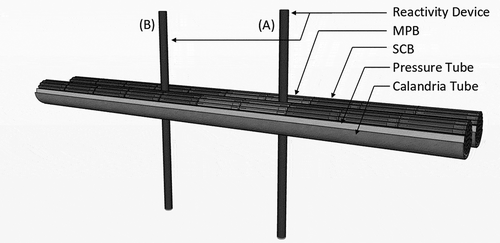
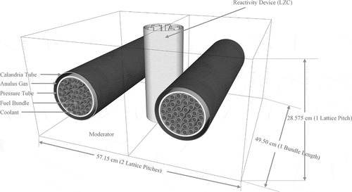
PHWR cores consist of a horizontal, unpressurized, vessel filled with heavy-water moderator, pierced axially by fuel channels arranged in a rectangular lattice with a pitch of 28.6 cm. Each fuel channel consists of two concentric tubes: an inner pressure tube and an outer calandria tube. The 10-cm-diameter pressure tube contains twelve 50-cm-long fuel bundles cooled by the pressurized heavy-water coolant. Reactivity devices (e.g., rods) are vertical and located between fuel channels. It is anticipated that 4 MPBs will be present in the core at any given time,Citation3 usually located in central axial positions, such as positions 6 and 7 in two adjacent channels as shown in . It is therefore possible that the reactivity worth of a device may be affected by the type of fuel bundle (MPB or SCB) adjacent to it. For example, reactivity devices A and B in could, potentially, have different reactivity worths.
Fig. 1. Reactivity devices located between PHWR fuel channels.
PHWR cores are usually analyzed in a full-core representation of the reactor using a neutron diffusion code that derives its two-group homogenized macroscopic cross-sections from two-dimensional (2D) single-cell calculations. Reactivity devices are modeled using two-group macroscopic cross-section increments which are added to the lattice-homogenized macroscopic cross-sections in the lattice cells that include reactivity devices. The macroscopic cross-section increments are determined from three-dimensional (3D) supercell calculations. The full set of macroscopic cross sections required to solve the neutron-diffusion equation for a full-core PHWR model therefore include:
Bare-lattice cross sections generated for each type of lattice cell in the core using a 2D single lattice-cell transport calculation
Macroscopic-cross-section increments for reactivity devices located between fuel channels and perpendicular to the reactor axis, generated using a 3D supercell neutron transport calculation. The increment of a given macroscopic cross section for a particular reactivity device is defined as the difference between the homogenized supercell cross section in the presence of the reactivity device and the same cross section in the absence of the device. A three-dimensional supercell consists of two adjacent horizontal lattice cells and a vertically oriented reactivity device between them.
The cross-section increments for each reactivity device, along with the bare lattice two group cross sections for appropriate burnup values, are the building blocks of the full-core two-group neutron-diffusion model. In order to prove that the MPB behaves the same way as the SCB in a PHWR core, both the bare-lattice macroscopic cross sections and the reactivity-device cross-section increments need to be similar.
The bare-lattice homogenized cross sections for the MPB and the SCB have been previously studiedCitation3 and found to be virtually identical, for any practical purpose.
If reactivity-device macroscopic-cross-section increments can also be demonstrated to be nearly independent of the type of fuel adjacent to the reactivity device, the expectation is that the reactivity-device worth itself will be independent of the type of fuel adjacent to the device. This would be true for any depth of insertion of a given reactivity device and for any combination of reactivity devices present in the core at any given time. Therefore, a comparison of device cross-section increments is a prerequisite first step toward establishing that core reactivity for any combination of reactivity devices and depth of insertion is not significantly affected by the anticipated presence of 4 MPBs in the proximity of reactivity devices. Should such increments be found to be unaffected by the proximity of MPBs, then only a limited number of full-core configurations would have to be analyzed, with the purpose of confirming that core reactivity and transient behavior are, indeed, unaffected by the proximity of MPBs to reactivity devices. On the other hand, should such increments be found to be affected by the proximity of MPBs, a larger number of full-core calculations would be needed, to determine which reactivity device configuration is most affected and to adjust control routines to account for the different device reactivity worth.
This work compares the reactivity-device incremental cross sections for the MPB and the SCB. The reactivity devices that are studied are: stainless-steel adjuster absorbers (AAs), shutoff absorbers (SAs) and liquid zone controllers (LZCs).
II. MOLYBDENUM-PRODUCING BUNDLE
The MPB proposed inCitation3 is designed to be neutronically and thermal-hydraulically equivalent to the SCB and has the capacity to produce ~4000 six-day Curies of 99Mo when irradiated for ~20 days in a PHWR. The geometry of the MPB is identical to that of the SCB, having the same diameters for fuel pellets, cladding and bundle as the SCB. This allows the MPB to have an identical hydraulic resistance to the SCB and be compatible with the fuel handling devices, most notably, the fueling machine.
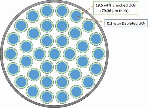
Each fuel pin of the MPB is divided in two regions: an inner region consisting of 0.2 wt% depleted UO2 fuel and an outer region consisting of high-assay low-enriched (HALEU) UO2 fuel with 19.5 wt% enrichment. The 19.5 wt% enrichment is chosen to be below the upper limit for low-enriched uranium to avoid proliferation concerns and to be sufficiently high to allow 99Mo extraction by already existing techniques.Citation5 The MPB layout used in this work is adopted from CitationRef. 3 and reproduced in .
Fig. 2. A schematic of the 37-element Molybdenum-99 producing bundle.Citation3
A 20-day irradiation, which corresponds to a burnup of 906.62 MWd/t(U) based on a bundle power of 900 kW and a bundle specific power of 45.33 kW/kg, is sufficient to reach the maximum activity of 99Mo inside the fuel pins.Citation3 Beyond 20 days, the rate of production of 99Mo activity in the fuel pins balances the rate at which 99Mo is lost due to radioactive decay.Citation6
III. PHWR REACTIVITY DEVICES
The PHWR has four different control device systems: the AAs, SAs, LZCs and control absorbers (CAs), which are identical to SAs. Consequently, only the three distinct reactivity devices (AA, SA and LZC) are studied in this work.
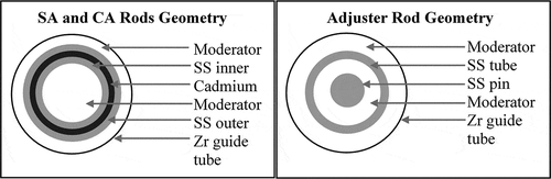
The stainless-steel-based AAs are of a pin-in-tube design with a central pin surrounded by a hollow stainless-steel tube. The space between the pin and the tube is occupied by the moderator. The diameters of the pin and of the surrounding tube are constant everywhere along the length of the AA. AAs move within a perforated zirconium-alloy guide tube located in the moderator. There are six different types of AAs, each with a specific pin and tube thickness.
The SAs, which are identical to CAs, are comprised of a hollow tube of cadmium sandwiched between stainless steel layers. The thickness of the two layers of stainless steel, as well as that of the cadmium tube, is the same over the length of the tube. SAs move within a perforated zirconium-alloy guide tube located in the moderator. The geometries, dimensions and material compositions for SAs and AAs are taken from CitationRef. 7 are shown in , and listed in , respectively.
TABLE I AA and SA Design SpecificationsCitation7
TABLE II AA and SA Material CompositionsCitation7
Fig. 3. Cross sectional view of PHWR shutoff absorber and adjuster absorber rods.
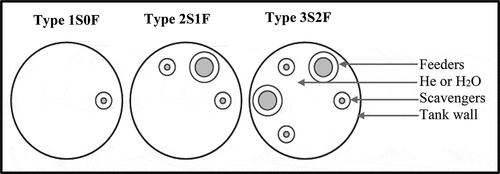
The LZCs consist of a cluster of tubes inside a zirconium-alloy outer tube. Each LZC compartment has at least one scavenger or feeder tube for H2O and one bubbler or balance tube for Helium. The arrangement of the LZC inside the PHWR is such that there are either three LZCs stacked on top of each other (central columns) or two LZCs stacked on top of each other (outer columns) resulting in LZC configurations which differ in the number of feeder/balance and scavenger/bubbler pipes that pass through the tank to supply other LZC compartments within the column. In total, there are three different LZC designs depending on the vertical location in the core. They are identified as Type 3S2F, Type 2S1F and Type 1S0F. The first digit in the LZC type corresponds to the number of the scavenger and bubbler tubes, and the second number corresponds to the number of feeder and balance tubes. All LZC compartments are assumed to be made of zirconium alloy with the same material composition as the one for AA and SA guide tubes. The design information for LZC is extracted from CitationRef. 8. A cross sectional view of the LZC showing the arrangement of feeder and scavenger tubes within the LZC compartment is presented in .
Fig. 4. Cross sectional view of PHWR liquid zone controller compartment.
IV. THREE-DIMENSIONAL SUPERCELL MODEL
IV.A. Supercell Components
The orthogonal orientation of the PHWR reactivity-control devices with respect to the fuel channel requires a full 3D model to capture the variations in neutron flux along the length of the fuel channel and locally, near reactivity control device components. The commonly employed model is a 3D “supercell” configuration consisting of two 3D lattice cells and a perpendicular reactivity device located at the center, between the two lattice cells. The 3D supercell model is illustrated in .
Fig. 5. A 3D PHWR supercell configuration with two fuel lattices and a reactivity device in the axial center.
IV.B. Homogenization Region
To capture the change in lattice homogenized macroscopic cross sections induced by the presence of a reactivity device (cross-section increments), two different regions are defined: an inner region and an outer region, as shown in , each with a volume equal to that of a 3D lattice cell of size 28.75 cm × 28.75 cm × 49.50 cm. The inner region extends from the first bundle mid-plane to the second bundle mid-plane. The outer region consists of the two regions extending from each bundle mid-plane to the respective model boundary. Only the inner region is specified as the region-of-interest and is used to homogenize and energy-condense macroscopic cross sections in order to derive the incremental cross sections and supercell reactivity in the presence of a reactivity device.
Fig. 6. PHWRD 3D supercell face view and homogenized inner region.

The homogenized and energy-condensed cross-sections are calculated based on the detailed cross sections using EquationEq. (1)(1)
(1) :
where is the homogenized and condensed cross section for reaction x (absorption, fission, etc.), for condensed energy group G, Vr is the volume of subregion r,
is the macroscopic cross section of reaction x in subregion r for energy group g, and
is the flux in subregion r for energy group g.
Two sets of homogenized cross sections are calculated: one in the absence of the reactivity device , and one in its presence
. The macroscopic cross-section increments are then calculated as
The supercell reactivity increments are calculated as the difference between the supercell reactivity in the presence and in the absence of the reactivity device:
The absence of the reactivity device is defined as rod removed for AA and SA and as fully drained for LZC. The presence of the reactivity device is defined as rod inserted for AA and SA and as completely filled for LZC. Simulations produce a complete set of incremental macroscopic cross sections.
IV.C. Representation of Fuel-Bundle Geometry
Each lattice cell consists of 37 fuel elements arranged in four concentric rings and pressurized heavy water coolant inside the pressure tube that is enclosed within a calandria tube surrounded by a heavy water moderator. The annular gap between the pressure tube and the calandria tube is filled with helium.
Modern, three-dimensional transport codes, (e.g., DRAGON) are capable of using explicit representations of the 37 fuel elements in each of the two fuel bundles included in the supercell model. At the same time, traditional 3D models of PHWR reactivity devices, developed in the late 1990s, have used simplified geometries of fuel bundles, referred to as “annularized” geometries. Such models are still used in routine production calculations. The annularized geometry is described in CitationRef. 9. The region inside the pressure tube is usually pre-homogenized into four concentric annuli, each corresponding to a fuel ring. The homogenized properties of each annulus are determined by flux-volume homogenization of fuel, cladding and coolant using the flux solutions of equivalent problems in 2D geometry. This work calculates incremental cross sections using both a detailed model and an annularized model of the fuel bundles in order to investigate any differences between the two sets of calculated cross section increments.
V. TRANSPORT-CODE MODEL AND CALCULATIONS
V.A. Transport Code
Calculations of the incremental cross-sections for the PHWR reactivity devices are performed using the neutron transport code DRAGON version 3.06L (CitationRef. 10) and the 69-group IAEA WIMS-D Library Update Project microscopic cross library (WLUP) (CitationRef. 11) DRAGON can solve the 2D or 3D integral neutron transport equations using either the Collision Probabilities (CP) method or the Method of Characteristics (MOC). For the current analysis, the 69-energy-group CP method was applied to a 3D supercell configuration comprising two side-by-side fuel lattices oriented parallel to the reactor axis and a reactivity device perpendicular to the reactor axis, located between the two cells, midway along the axial length of the fuel bundles, as shown in .
V.B. Detailed Bundle Model
Fuel pins in each bundle are represented explicitly, using the “CLUSTER” geometry type in DRAGON. Fuel pins are split into 11 radial regions and the modified Stamm’ler methodCitation12 is used to perform resonance treatment treating each radial region as a distinct resonance domain. Because the MPB and SCB have identical geometries, the same 3D models can be used to represent either, with only the composition of the fuel material in each region being different. The outermost region of the MPB contains enriched fuel and the 10 remaining regions contain depleted fuel. All SCB regions contain natural uranium.
No additional spatial discretization is added in the fuel or other parts of the model due to the complex and computationally intensive nature of the 3D transport solution. Reflective boundaries are used on all six boundaries of the supercell model, thus simulating an infinite repeated array of the base supercell configuration consisting of two fuel bundles and a control device.
The fuel temperatures in each discrete region of the pin are set, for each bundle type, according to the calculated radial temperature profiles in CitationRef. 4 given at zero burnup or 20-day burnup. The radial temperature profile for the MPB is significantly different from that for the SCB (CitationRef. 3). The use of correct radial variation of the fuel temperatures ensures accurate prediction of the reactivity device incremental cross-sections compared to the use of a uniform fuel temperature as typically done in supercell calculations.
V.C. Annularized-Bundle Model
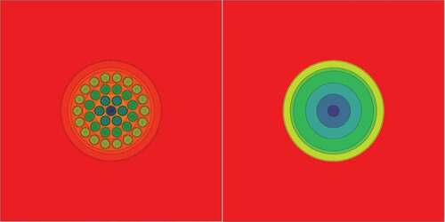
The annularized model is obtained by first performing 2D neutron transport calculations in 69-energy groups (including self-shielding), followed by material homogenization into annuli. Four different fuel “pastes” are computed, one for each annular region corresponding to each fuel ring. Each paste is obtained by homogenizing fuel, cladding and coolant materials. From the 2D calculation step, a new set of 69-group macroscopic cross sections is formed for each paste, which is then used in the 3D calculation. The cluster geometry of the 37-element fuel pins and the annularized geometry with concentric homogenized annuli are depicted in . Aside from the homogenization of the fuel, cladding and coolant, the annularized-model parameters such as spatial discretization and tracking path density are the same as for the detailed model.
Fig. 7. 37-Element explicit (left) and annularized (right) models.
V.D. Supercell Calculations
Three-dimensional supercell calculations are performed for the MPB, as well as the SCB, at zero burnup and 20-day burnup (906.62 MWd/t(U)) which corresponds to the maximum residence time of the MPB inside the core. To ensure accurate representation of the fuel compositions at 20-day burnup, burnup calculations are performed for both MPB and SCB using 2D lattice models and small burnup steps. Detailed fuel compositions in each fuel ring are then transferred to the 3D supercell models to determine the incremental cross sections and reactivity changes for AA, SA and LZC.
Three cases are analyzed for each reactivity device and for each bundle type: 1) two bundles, 2) two bundles and guide tube in place, 3) two bundles, guide tube and reactivity device in place. Macroscopic cross sections are calculated in 69-energy groups then condensed into two energy groups and spatially homogenized. In total, for each reactivity device, two sets of incremental cross sections are defined:
ΔΣGuide Tube – Incremental cross sections for a (empty) tube”, unoccupied by the movable absorber that is part of the reactivity device. For liquid zone controllers, the tube represents the outer LZC compartment and the inner scavenger and feeder tubes. The part of LZC that is inside the outer tube and outside the scavenger/feeder tubes is filled with helium. For solid control rods, the tube is the guide tube. It is filled with moderator
ΔΣDevice – Incremental cross sections for a rod-based reactivity device that is fully inserted or a LZC that is completely filled with light water within the cell limits.
shows the set of 9 incremental cross sections that are computed for the MPB and the SCB. For the sake of comparison, incremental cross sections (for both SCB and MPB) are calculated using both the detailed model which uses the explicit “cluster” geometry available in DRAGON and the simplified (annularized) fuel-bundle model used in production calculations.
TABLE III Set of Incremental Cross Sections
VI. SIMULATION RESULTS
Incremental macroscopic cross sections and corresponding supercell reactivity increments are presented in for both MPB and SCB. Differences are presented as MPB value – SCB value, while percentage differences are presented as (MPB value – SCB value)/SCB value × 100%. Because guide tubes for different AA types are identical, their incremental properties are only presented once.
TABLE IV Adjuster Absorbers Homogenized Incremental Cross Sections at Zero Burnup
TABLE V Shutoff Absorbers Homogenized Incremental Cross Sections at Zero Burnup
TABLE VI Liquid Zone Controllers Homogenized Incremental Cross Sections at Zero Burnup
TABLE VII Guide Tubes Homogenized Incremental Cross Sections at Zero Burnup
TABLE VIII Adjuster Absorbers Homogenized Incremental Cross Sections at 20-day Burnup
TABLE IX Shutoff Absorbers Homogenized Incremental Cross Sections at 20-day Burnup
TABLE X Liquid Zone Controllers Homogenized Incremental Cross Sections at 20-day Burnup
TABLE XI Guide Tubes Homogenized Incremental Cross Sections at 20-day Burnup
TABLE XII Annularized Fuel Adjuster Absorbers Homogenized Incremental Cross Sections at Zero Burnup
TABLE XIII Annularized Fuel Shutoff Absorbers Homogenized Incremental Cross Sections at Zero Burnup
TABLE XIV Annularized Fuel Liquid Zone Controllers Homogenized Incremental Cross Sections at Zero Burnup
It is worth noting that, because the supercell boundary conditions are periodic, the supercell reactivity increment corresponding to the insertion of the reactivity device does not represent the reactivity worth of a single device, but rather the reactivity worth of an array of devices repeated every two lattice pitches, in an infinite lattice. Nonetheless, the percent differences between the MPB- and SCB-based supercell reactivity increments are representative of the percent difference between the device reactivity worth when located near a MPB or a SCB.
VI.A. Incremental Cross Sections and Reactivities at Zero Burnup
The two-group homogenized incremental cross sections, ΔΣDevice, and incremental supercell reactivity for AA, SA and LZC are first calculated using fuel properties corresponding to zero burnup and presented in , , and , respectively. The reference supercell reactivity is 42.36 mk for the SCB and 43.20 mk for the MPB.
The incremental macroscopic cross sections of all reactivity devices are very similar for the two bundle types. It bears mentioning that such cross-section increments represent merely a convenient mathematical way of modeling a reactivity device in a two-group diffusion calculation and cannot be directly related to the neutron cross sections of the material making up the device. It is obvious, for example, that fission and production cross sections for the reactivity-device materials are zero, whereas increments for such average macroscopic cross sections can be non-zero. This is due to the fact that the homogenization volume includes fuel. Differences between device cross-section increments obtained for the two fuel types do not, therefore, have any operational implications. The operationally-meaningful quantity is the percent difference between the supercell reactivity increments. It is desirable that the supercell reactivity increments corresponding to a device’s insertion be very similar for the two bundle types.
When comparing the calculated supercell reactivity increments for the MPB and the SCB, they are found to be very similar for all reactivity devices, with the difference being less than 2.0% (, , and ). The largest difference for AA occurs for Type 3, whereby the difference is 3.94 mk (−1.9%). For SA, the difference is 19.71 mk (−1.7%). The highest difference for LZC occurs for Type 1S0F whereby the difference is 1.58 mk (−0.6%).
The incremental cross sections and incremental supercell reactivity for guide tubes at zero burnup are shown in and are very similar for both bundle types. The calculated MPB-to-SCB supercell reactivity-increment differences are less than 5.0% for all guide tubes.
VI.B. Incremental Cross Sections and Reactivities at 20-Day Burnup
For 20-day burnup, the 2-group homogenized incremental reactivity device cross sections, ΔΣDevice, and incremental supercell reactivity are presented in , , and . The reference supercell reactivity is 13.73 mk for the SCB and 14.00 mk for the MPB.
Just like in the zero burnup case, the incremental macroscopic cross sections of all reactivity devices at 20-day burnup are very similar for the two bundle types. The difference in incremental supercell reactivity between the MPB and SCB is less than 1.5% for all reactivity devices. The highest incremental-reactivity difference for AA occurs for Type 3 whereby the difference is 2.18 mk (−1.1%). For SA, the incremental-reactivity difference is 11.11 mk (−1.0%). The highest incremental-reactivity difference for LZC occurs for Type 3S2F whereby the difference is 0.20 mk (−0.1%).
The incremental cross sections and incremental supercell reactivity for guide tubes at 20-day burnup are given in and are very similar for both bundles. The calculated difference in incremental supercell reactivity between the MPB and SCB is less than 4.0% for all guide tubes.
VI.C. Comparison of Incremental Cross Sections and Incremental Supercell Reactivities between Cluster Fuel Model versus Annularized Fuel Model
Production supercell calculations have been customarily performed using the annularized fuel-bundle geometryCitation9 because three-dimensional transport-calculations for the detailed model are computationally expensive. In this study, the reactivity device incremental cross sections and incremental supercell reactivities obtained using the annularized fuel-bundle model are compared with those obtained using the detailed fuel-bundle model. The modeling of the reactivity devices in this comparison is the same, namely concentric cylindrical representation is used to model AA and SA, and cluster geometry to model multiple feeders and scavenger tubes of the LZC.
, , and present the incremental cross sections using the annularized fuel geometry at zero burnup for AA, SA and LZC, respectively. Results are consistent with results obtained using the detailed-geometry (cluster) model, in that for both fuel types, the calculated difference in incremental supercell reactivity between the MPB and SCB is less than 1.5% for all reactivity devices. Similar to when using the detailed, cluster, geometry, the highest reactivity difference for AA occurs for Type 3 whereby the incremental-reactivity difference is 2.48 mk (−1.3%). For SA, the difference is 11.23 mk (−1.1%). The highest difference for LZC occurs for Type 1S0F whereby the difference is 1.01 mk (−0.4%), a result similar to the one obtained using the detailed, cluster, geometry.
A comparison of the cluster geometry representation with the annularized representation for AA, SA and LZC is presented in , respectively, where differences in the two-group homogenized incremental cross sections and incremental supercell reactivity are given in percentage difference, defined as (annularized geometry - cluster geometry)/cluster geometry × 100%.
TABLE XV Cluster versus Annular Fuel Homogenized Incremental Cross Sections for Adjuster Rods at Zero Burnup
TABLE XVI Cluster versus Annular Fuel Homogenized Incremental Cross Sections for Shutoff Absorbers at Zero Burnup
TABLE XVII Cluster versus Annular Fuel Homogenized Incremental Cross Sections for Liquid Zone Controllers at Zero Burnup
and show that the supercell reactivity increments for AA and SA can differ substantially (reactivity difference is between 7.0% to 10.0% for AA and between 10.0% to 11.0% for SA) for the two geometric representations and these differences exist for both bundle types. For LZC, the supercell reactivity increments are closer (less than 1.0% difference) for the two geometric representations, as shown in .
The highest % reactivity-increment difference for AA is −9.1% for MBP and −9.6% for SCB, for SA is −10.4% for MPB and −11.0% for SCB, and for LZC is −0.4% for MPB and −0.6% for SCB. The negative sign of the % reactivity-increment difference between the two modeling choices indicates that the annularized representation of fuel pins underestimates the supercell reactivity increment, and hence the device reactivity worth, compared to that calculated by the cluster representation. The magnitude of the underestimation is highest for SA, which has the highest calculated supercell reactivity, following AA and then LZC.
VII. CONCLUSION AND FUTURE WORK
The study shows that the incremental effects of PHWR reactivity devices on bare lattice properties are very similar for MPB and SCB. Maximum differences in reactivity-device supercell reactivity increments, and hence in device reactivity worth, are less than 2% for any given device at zero burnup and less than 1.5% at 20-day burnup. Consequently, these differences have no operational implication. While a 2% across-the board reactivity-device difference might be thought to have some impact on the achievable burnup, it will be noted that only four MPBs are expected to be in the core at any given timeCitation3 and, therefore, only one or, at most, two reactivity-device instances may have their reactivity worth altered by their proximity to an MPB. As a result, the difference in the overall core reactivity will be negligible and no discernible effect on the achievable burnup is expected.
It is therefore concluded that the use of up to four MPBs in a PHWR core is entirely compatible with the current reactivity devices and it is anticipated that no changes to reactivity devices will be necessary to allow the use of MPBs. To confirm this conclusion, it is desirable to perform some full-core, three-dimensional static and space-time transient analyses, to verify that the static core reactivity and time-evolution of power in a transient scenario are not affected by the presence of the MPBs.
The study also shows that the use of the annularized bundle geometry to calculate reactivity-device cross-section increments underestimates the incremental supercell reactivity and hence the device reactivity worth. Consequently, the use of the annularized model is conservative. However, for a more accurate core reactivity calculation especially during fast transients, a detailed, cluster, representation of the bundle is recommended.
For the future, it is recommended to perform some transient analyses to ascertain the difference in transient simulation results between the case when cross-section increments are calculated using an annularized fuel-bundle geometry and the case when cross-section increments are calculated using a detailed, cluster, fuel-bundle geometry.
Notes
a CANDU is a trademark of Atomic Energy of Canada Limited used under license by Candu Energy Inc.
References
- D. N. ABRAMS et al., Lessons Learned from the Shutdown of the Chalk River Reactor, Health Canada, (2008).
- Manual for Reactor Produced Radioisotopes, IAEA-TECDOC-1340, International Atomic Energy Agency, Vienna (2003).
- E. NICHITA and J. HAROON, “Molybdenum-99-producing 37-element Fuel Bundle Neutronically and Thermal-hydraulically Equivalent to a Standard CANDU Fuel Bundle,” Nucl. Eng. Des., 307, 86 (2016); https://doi.org/https://doi.org/10.1016/j.nucengdes.2016.06.036.
- J. HAROON and E. NICHITA, “A Comparative Study of Reactivity Feedback Effects for A HALEU Molybdenum-producing PHWR Fuel Bundle and A Standard PHWR Fuel Bundle,” Nucl. Eng. Des., 361, 110545 (2020); https://doi.org/https://doi.org/10.1016/j.nucengdes.2020.110545.
- Non-HEU Production Technologies for Molybdenum-99 and Technetium-99m, IAEA-No. NF-T-5.4, International Atomic Energy Agency, Vienna (2013).
- National Research Council, Medical Isotope Production without Highly Enriched Uranium, The National Academies Press, Washington (2009).
- C. CARRE, Feasibility Study of Recycling Uranium Retreatment, Ecole Polytechnique De Montreal, Montreal (2011).
- D. CHO et al., “Sensitivity of Physics Parameters for Establishment of a Burned CANDU Full-Core Model for Decommissioning Waste Characterization,” J. Nucl. Sci. Technol., 48, 2, 215 (2012); https://doi.org/https://doi.org/10.1080/18811248.2011.9711695.
- M. OVANES and J. V. DONNELLY, “Validation of 3-Dimensional Neutron-Transport Calculations of CANDU Reactivity Devices,” 21st Nuclear Simulation Symposium, Ottawa, Canadian Nuclear Society, 2000.
- G. MARLEAU, A. HEBERT, and R. ROY, A User Guide for DRAGON, Ecole Polytechnique de Montreal, Montreal (2013).
- WIMS-D Library Update, STI/PUB/1264, International Atomic Energy Agency, Vienna (2007).
- A. HEBERT and G. MARLEAU, “Generalization of the Stamm’ler Method for the Selfshielding of Resonant Isotopes in Arbitrary Geometries,” Nucl. Sci. Eng., 108, 230 (2003); https://doi.org/https://doi.org/10.13182/NSE90-57.