
Abstract
Markets are changing as the result of (1) the addition of variable wind and solar that causes highly volatile electricity prices and (2) the goal of a low-carbon economy. These changes require economic low-carbon dispatchable electricity, which is now provided by natural gas turbines, and dispatchable heat for industry and commerce. Moreover, nuclear plant requirements have changed in the last 50 years with high capital costs in western countries. An alternative plant design is described with the nuclear island separated from a nonnuclear power block by large-scale heat storage. All heat from the reactor is sent to heat storage. The nuclear reactor operates at base load and is sized to meet average energy demand over a period of days. Heat storage provides variable heat to industry and/or the power block. The nonnuclear power block is sized to provide peak electricity capacity (kilowatts) several times the nuclear reactor base-load power output to maximize revenue by sale of electricity at times of high prices. The power block capital cost (heat exchanger, turbine, and generator) per unit of generating capacity (kilowatt) is less than a conventional gas turbine that includes heat generation (compressor and burner) and the power block (turbine and generator). Nuclear reactor capital cost is reduced by fewer requirements on the nuclear system (not connected to the grid) and nuclear-quality construction for only the reactor. Operating costs (security, maintenance, etc.) are minimized by separation of the nuclear reactor plant from balance of plant. Low-cost heat storage provides a competitive economic advantage to heat-generating technologies (nuclear, concentrated solar power) over electricity-generating technologies (wind, solar, photovoltaic) with more-expensive battery or other electricity storage systems in providing dispatchable electricity to the grid.
I. INTRODUCTION
A new nuclear power plant design paradigm is described herein with the nuclear island separated from the nonnuclear power block or industrial heat customer by large-scale heat storage. The reactor delivers heat to storage. Heat from storage goes (1) to the power block to produce electricity or (2) to meet industrial or commercial heat demand. This paper integrates the results of a series of workshops led by the author on heat storage Citation1–3 and rethinking nuclear plant design.Citation4 The need to rethink nuclear plant design is based on two observations:
Changing energy markets: The historic role of nuclear energy has been to provide base-load electricity. Because of the high capital cost and low operating cost of nuclear power plants, the economics favored base-load reactor operation. Variable heat and electricity have been provided by fossil systems with low capital costs and high operating costs. The goals of a low-carbon energy system and the addition of nondispatchable wind and solar create large variations in prices with time and thus large economic incentives to provide dispatchable heat and electricity.
High capital costs: The capital cost of nuclear power plants in western countries has significantly increased for multiple reasons.Citation5,Citation6 One cause is that nuclear plant requirements have evolved over the last 50 years. The original nuclear plant designs followed those of coal plants, i.e., tight integration of the heat source with the turbine generators. Changing licensing, safety, and security requirements suggest that a lower-cost option may be to separate the nuclear island from the power block with a clear separation of the nuclear island with nuclear construction, operating, and security requirements from the power block built and operated to industrial standards. Heat storage built to nonnuclear standards separates the reactor block from the power block.
The paper first examines the changes in the market that create economic incentives to change plant design (Sec. II) followed by the new plant system description (Sec. III). The system description could apply to any power reactor technology: light water reactors (LWRs), sodium fast reactors (SFRs), high-temperature gas-cooled reactors (HTGRs), and salt-cooled reactors. Sections IV, V, and VI describe the implications of this alternative design paradigm on heat storage, the power block, and the nuclear island. Section VII discusses institutional and regulatory impacts while Sec. VIII discusses economic and business implications. Today, several advanced reactors propose to include heat storage that separates the nuclear power block from the conventional power block. The TerraPowerCitation7,Citation8 reactor is a SFR whereas the Moltex reactorCitation9 uses a clean molten salt as a coolant.
This paper includes heat storage experience from concentrated solar power (CSP) plants and fossil heat storage studies that are applicable to heat storage in nuclear plants. Many CSP systems incorporate storage for two reasons. First, storage enables selling electricity after the sun sets at higher prices. Second, on partly cloudy days the solar input is highly variable. Heat storage is used to enable steady-state electricity output rather than rapidly variable output from the CSP system. Heat storage is being considered for fossil plants.Citation4 First, many fossil plants are now being used as peaking plants for a limited number of hours per year. If a station has several units, there are economic incentives to shut down all but one of the steam boilers, add heat storage, and use the steam turbine generators from the multiple units. The one steam boiler operates near base load with variable electricity output by using multiple existing steam turbine generators. This minimizes the operational difficulties and costs associated with operating multiple boilers with variable output. The second application is for future fossil plants with carbon-capture and sequestration (CCS) systems. These plants have high capital cost and significant challenges in varying power output because of the CCS systems. There are incentives to add heat storage for variable output from a base-load fossil plant with CCS.
II. CHANGING MARKETS
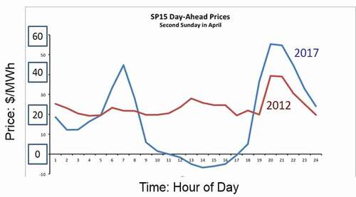
Electricity markets are changing because of the goals of a low-carbon energy system and the addition of nondispatchable wind and solar that creates large variations in prices with time. shows wholesale prices over one spring day in California in 2012 and 2017. In 2012 the price of electricity was controlled by natural gas with peak wholesale electricity prices in the early evening at times of peak electricity demand. By 2017 the large-scale addition of solar resulted in collapse of wholesale electricity prices in the middle of the day with higher prices before sunrise and as the sun goes down. Wholesale prices in the middle of the day can become negative as conventional power plants bid negative prices to remain online at minimum output so they are able to ramp up in the evening when electricity prices climb. The value of solar decreases as more solar is addedCitation10,Citation11 as has been seen in multiple markets. This limits the large-scale economic deployment of wind and solar photovoltaic (PV) systems.
Fig. 1. Wholesale California electricity prices over 24 h on a spring day.
Historically, the daily to seasonal variations in wholesale electricity prices have been small. Fossil fuel plants have low capital costs and high fuel costs. It is economic to operate fossil plants at variable load because the money is in the fuel. The development of nuclear power plants created an energy production system with high capital costs and low operating costs. The economics resulted in nuclear plants operating at base-load with fossil plants operating at variable load to meet variable electricity demand. Nuclear plants in some countries such as France have operated for decades with variable output. It is economics (not technology) that has resulted in nuclear plants operating as base-load power plants.
Recent studiesCitation12 of the impacts of wind and solar on California electric wholesale markets have provided insights into the long-term market effects of wind and solar. In the United States, wholesale electricity prices have been decreasing. The primary cause on a national basis has been the reduction of natural gas prices from fracking. However, California has aggressively pushed wind and solar relative to most of the United States. As a consequence, California provides a basis to understand the future impacts of wind and solar on wholesale electricity prices. Three conclusions follow from these studies:
Revenue to base-load power plants goes down with large-scale wind and solar additions.
There are large increases in the volatility of electricity prices. This creates large economic incentives for dispatchable electricity with fast response to produce electricity at times of higher prices (low wind/solar output) and avoid selling electricity at times of low or negative prices (high wind/solar output). Today, this favors gas turbines fueled with natural gas.
As more wind or solar is added, the revenue per installed kilowatt of capacity of wind and solar goes down. This effect is larger for solar than wind. Revenue collapse limits the large-scale deployment of wind and solar unless large subsidies or markets are developed to absorb massive amounts of electricity to reduce times of very low electricity prices.
Historical studiesCitation13 on electricity prices that cover multiple regions of the United States come to similar conclusions. This change in the market creates incentives for electricity storage systems to buy electricity at times of low prices and sell at times of high prices to address hourly to daily price variations in electricity prices.
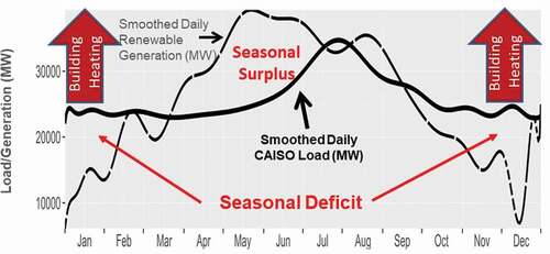
There are limits to such storage systems because of the seasonal variations in wind and solar. shows the smoothed electricity demand for California over a period of 1 year and the smoothed generating profile of wind and solar over the same time if sufficient wind and solar systems were built to meet the total electricity demand of California. That is, the total production of electricity from wind and solar matches the total demand for electricity. There is a seasonal mismatch between production and demand with excess production in the spring and early summer. That mismatch will dramatically increase if there is significant movement of building heating loads to electricity.
Fig. 2. Smoothed daily California electricity demand and smoothed daily renewable generation with total annual renewable generation equal to total annual electric demand (Courtesy of S. Brick, California Case Study, Clean Air Task Force).
The cost of electricity (kilowatt hours) from wind and solar is low. However, for every unit of generating capacity (kilowatts), large amounts of energy storage and assured generating capacity are needed for times of low wind and solar output. The economics of large-scale wind and solar systems are determined by the economics of storage and assured generating capacity, not by the cost of producing electricity from wind and solar systems. This is why electricity costs have gone up in Germany, Denmark, California, and other locations that have attempted to create electricity systems based on wind and solar. Small amounts of wind and solar reduce electricity prices while large amounts increase the price of electricity to the consumer.
If a green-field electricity (start from scratch) system were built in the United States today with the goal to minimize costsCitation5,Citation14 to the customer, the majority of electricity would be generated using natural gas with added wind and solar in locations with good wind or solar inputs. Wind and solar act in a fuel-saving mode. Most electricity would be generated by natural gas because wind and solar provide electricity to the grid less than half the time. The peak natural gas generating capacity would be close to the peak electricity demand for most of the United States. In northern climates, peak loads occur in winter at times of minimum wind and solar output.
If there are limits on greenhouse gas emissions, replacements are required for the gas turbine that provides most of the electricity (kilowatt hours) and most of the assured generating capacity (kilowatts). StudiesCitation14 of such systems show that the minimum cost system contains a mixture of wind, solar, nuclear, and storage. Nuclear energy provides both energy (kilowatt hours) and assured generating capacity (kilowatts). The assured generating capacity to avoid blackouts is as important as the energy if there are tight restrictions on greenhouse gas emissions. These studies have considered existing storage technologies, but they have not considered large-scale heat storage coupled to nuclear power plants. What the electricity market needs for a low-carbon world with wind and solar is a low-carbon replacement for the gas turbine.
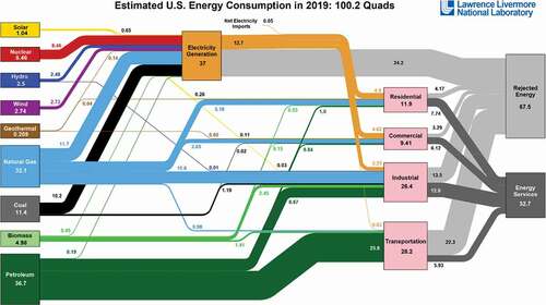
Separate from the electricity market is the heat market with different characteristics. Most heat is provided by fossil fuels (). In the United States, electricityCitation15–Citation17 provides slightly more than 17% of energy demand to customers. The industrial heat load alone is about twice the total the electricity output. While heat and electricity are different, in most industrial applications (given technology and economic limits of heat pumps), one unit of electricity becomes one unit of heat using resistance heaters. Much of this market is for steady-state heat demand. In this market nuclear energy has a competitive advantage.Citation16 Because of thermodynamics (Carnot cycle), it takes several units of heat to produce a unit of electricity. Nuclear and fossil plants produce cheap heat and more expensive electricity. This makes wind and PV that produce electricity expensive sources of heat separate and independent from the inability to deliver continuous energy to industrial processes.
Fig. 3. Energy flow diagram of the United States for 2019 (CitationRef. 15).
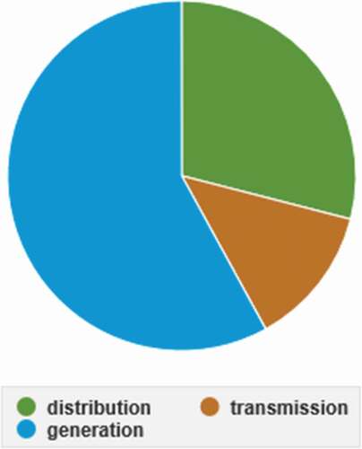
Separate from the cost of energy is the cost of electricity transmission and distribution. shows the cost breakdownCitation18 of delivered electricity: production (generation) (56%), transmission (13%), and distribution (31%). Cheap electricity is significantly more expensive than heat because of the delivery costs to the user.
Fig. 4. Cost breakdown for delivered electricity in the United States in 2019.
III. SYSTEM DESCRIPTION
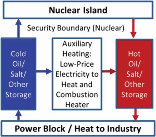
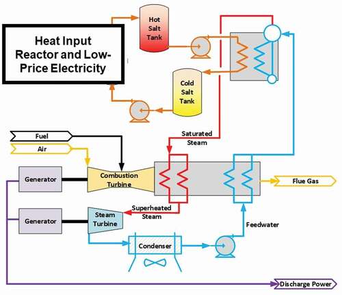
To address the changing markets requires rethinking the energy system for a world that has large quantities of nondispatchable energy sources (wind, solar, run-of-the-river hydroelectric) and limits on carbon dioxide emissions. shows the new design paradigmCitation4,Citation16,Citation17 in terms of heat and electricity flows. provides added detail showing flow of fluids among the reactor, heat storage, and the power block, using the existing two-tank heat storage system. The intermediate loop of the reactor transfers heat to storage. The technology proposed today for sodium, lead, and salt-cooled reactors is to use a nitrate salt intermediate loop. The system design is similar to that used in many CSP systems with the same salts.Citation19,Citation20 The reactor takes cold salt from a cold-salt storage tank, heats the salt, and sends hot salt to a hot-salt storage tank. Using today’s technologies, the power cycle takes hot salt, produces steam for the turbine generator, and returns cold salt to the cold storage tank. Longer-term power block options include air-Brayton and supercritical carbon dioxide cycles. The hot-salt tank also provides heat to industrial customers. For lower-temperature systems such as LWRs, the heat transfer fluid would be a heat transfer oil. Lower-temperature (<400°C) CSP systems use heat transfer oils. There are alternative intermediate-loop coolants and heat storage technologies. This system has several characteristics.
Fig. 5. Current and alternative design of nuclear power systems.
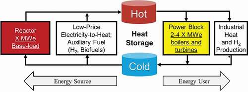
Fig. 6. Two-tank sensible heat storage system.
III.A. Decoupling Reactor Output from Electricity or Heat Output
The reactor is designed for average required energy demand over a period of hours up to 1 week. The power block is designed to meet market requirements. The peak electricity output may be several times the base-load output of the reactor. In this system nuclear reactors with heat storage and separate power blocks become a low-carbon replacement of gas turbines. Electricity is sold at times of high prices, which maximizes revenue.
III.B. Electricity Storage
The addition of wind and solar results in times of very low electricity prices. At such times (), electricity can be bought and converted into stored heat to produce electricity for sale at times of high prices. The only additional cost is the cost of electric resistance heaters and an incrementally larger heat storage system. The grid connections, main heat storage system, and power block already exist. Integrating energy storage with the power plant that is coupled to the grid is much less expensive than integrating a stand-alone storage system with the electricity grid.
If there are many hours of low-price electricity, there is a second option: using heat pumps to convert low-temperature heat into high-temperature stored heat.Citation21–25 Whereas one unit of electricity yields one unit of heat with a resistance heater, heat pumps can convert one unit of electricity into several units of high-temperature heat. If a cooling lake is associated with the power plant, it can be the source of lower-temperature heat. Such systems are called Carnot batteries. Many of these heat pump systems can be operated in both directions; that is, (1) electricity pumps heat from a lower-temperature reservoir to a higher-temperature reservoir and (2) when operated in reverse converts heat into electricity. For large systems, there may be a combination of Carnot heat pumps and resistance heaters where the heat pumps first come online as the price of electricity collapses and operate for many hours while the lower-cost electric resistance heaters are used only when there is a massive excess of electricity that is available for a limited number of hours. Heat pumps have higher capital costs than resistance heaters and thus economically would only be viable in systems with many hours of low-price electricity. Carnot heat pumps are under development but not yet a commercial technology.
The ability to buy and sell electricity would have major impacts on electricity prices by setting a minimum price for electricity. That would improve the economics of wind and solar. As discussed later, heat storage capital costs are estimated to be one to two orders of magnitude less than batteries and other technologies that store electricity and thus would replace many other storage technologies.
III.C. Low-Capital-Cost Generating Capacity
The electricity-generating capacity may be several times the base-load electricity-generating capacity. It is sized to match market demand.Citation4,Citation9 This system is built to industrial, not nuclear, standards to minimize capital costs. The power cycle will be operating only part of the time. The technical goal is a power cycle with the ability to rapidly start and vary power levels to match demand. The economic goal is low capital costs per unit of capacity (kilowatts)—substantially below conventional gas turbines or batteries and other electric storage systems.
III.D. Backup Combustion Heaters
There is the option to add a backup combustion heater () to heat the salt if storage is depleted and the reactor cannot provide sufficient heat. The fuel could be natural gas or low-carbon hydrogenCitation26–28 or low-carbon biofuels.Citation29 This feature provides assured peak electric-generating capacity. The capital cost of such a backup combustion heater is low. Combined with the power block, this provides a competitive advantage to provide a low-carbon replacement for the assured generating capacity provided by the gas turbine.
Capital Costs
The capital cost of providing assured generating capacity is less than an equivalent PV/wind system with electricity storage. The cost of batteries or other technologies is higher than the cost of heat storage as discussed below. If one buys 1 kW of PV or wind, 1 kW of storage capacity is needed to provide electricity at times of low-wind or low-solar conditions. If the storage capacity is a battery, 1 added kW of gas turbine capacity is required to back up the battery for assured generating capacity in the case of multiday cloudy weather or low-wind days. One requires multiple kilowatts of generating capacity to back up the wind or solar—batteries and then gas turbines.
Combustible Fuel Consumption
The low cost of heat storage versus electricity storage implies that the quantities of combustible fuel to provide assured generating capacity is lower—more storage is available.
III.E. Integration of Industrial Heat Markets and Electricity Markets
About 80% of all energy used by the customer in the United States is in the form of heatCitation15 as shown in . Electricity is less than 20% of energy consumption in the United States as shown by the gold-colored flows in . The total industrial heat demand in the United States is about twice the total electricity output. The future heat demand may be much larger. Many of the processes to convert biomass to liquid biofuels require massive quantities of heat and hydrogen.Citation29 The quantity of biofuels per unit of biomass can be almost doubled by addition of external heat and hydrogen.
Heat storage enables varying industrial production to provide more electricity at times of high electricity prices to (1) increase total revenue and (2) meet weekly to seasonal variations in electricity demand. Historically, fossil and nuclear cogeneration systemsCitation30 that produced electricity and steam provided heat and electricity to industry and then sold excess energy as electricity to the grid. The price of electricity was relatively constant (); thus, there were not large incentives on when to sell electricity to the grid. With the changes in the electricity market, electricity revenue is strongly dependent upon when electricity is sold. Industrial production requirements make it difficult to vary heat demand quickly on an hourly to daily basis to maximize revenue from electricity sales. However, many industrial processes can alter heat demand over a period of hours or days if there is a large economic incentive to do so. Large-scale heat storage eliminates the second-by-second requirement that industrial heat plus electricity output match reactor output. The new requirement becomes that industrial heat and electricity output match reactor output over a period of hours to 1 week. This added degree of freedom in operations enables altering industrial production to provide more electricity to the grid at times of high demand and prices.
III.F. Changing Functional Requirements for the Nuclear Reactors
The system design changes the functional requirements for the nuclear reactor. There are no grid requirements on the reactor. The reactor produces heat on its own schedule. Transients are minimized.
summarizes the characteristics of this system. The reactor is sized to meet average energy demands. The power block is sized to meet peak electricity demands with assured generating capacity. Heat storage, depending upon the market, is designed to meet daily to weekly variations in energy demand.
TABLE I System Characteristics
IV. STORAGE TECHNOLOGIES
IV.A. Storage Markets
The energy storage market is growingCitation31 with the market size and benefits from any storage technology dependent upon the cost of storage. If heat storage capital costs can be driven down to several dollars per kilowatt hour of heat, heat storage systems can provide variable electricity on an hourly to weekly basis with base-load operation of the reactor, with major savings to the electricity grid.Citation32 Electricity demand varies on (1) a daily cycle, (2) a multiday cycle tied to changing weather over several days, (3) holidays, (4) the weekday/weekend work cycle, and (5) seasonal variations driven by weather. On the production side, solar has a daily cycle and in many locations a multiday cycle of cloud cover. Wind has a multiday cycle in the middle latitudes. Both wind and solar have large seasonal variations in output () in the middle and higher latitudes. Nuclear can operate at steady state. In most low-carbon systems, there will be excess production capacity on weekends creating the incentive for large-scale heat storage at the weekly scale.
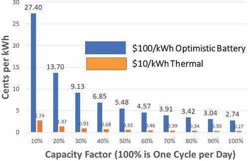
(CitationRef. 32) shows for two different technologies the storage costs in cents per kilowatt hour for different utilization rates. The costs are shown for batteries at the extremely optimistic capital cost of $100/kW.h (all figures in this paper are in U.S. dollars) and for thermal storage with a capital cost of $10/kW.h. As a point of comparison, the average cost of electricity in the United States is $0.12/kW.h. A utilization rate of 100% implies one storage cycle/day. A weekly storage cycle implies a utilization rate of 14%, i.e., once a week. For an optimistic battery capital cost of $100/kW.h, weekly storage costs exceed $0.20/kW.h. The cost of storage more than doubles the average cost of electricity. For a heat storage capital cost goal of $10/kW.h, storage costs are near $0.02/kW.h for weekly storage, which is a small fraction of the cost of electricity. The costs for daily storage are much less. It does not require much of an hourly to weekly variation in electricity prices to make very-low-cost heat storage economic.
Fig. 7. Cost of storage versus capacity factor.
Recent studiesCitation33,Citation34 have estimated the current costs of various storage technologies. The recently published U.S. Department of Energy (DOE) roadmapCitation35 for battery storage has a cost storage goal of $0.05/kW.h. The current capital costsCitation34 for the leading electricity storage technologies assuming 10-h storage are (1) pumped hydroelectric storage: $262/kW.h, (2) lithium ion batteries: $356/kW.h, and (3) compressed air energy storage (CAES): $119/kW.h. CAES is the most limited in terms of siting options. Existing large-scale thermal heat storage costs are below the long-term cost goals for battery storage, and advanced heat storage systems have capital cost goals of a few dollars per kilowatt hour. The very low cost of heat storage provides a massive competitive economic advantage to heat-generating technologies (nuclear, CSP) over electricity-generating technologies (wind, PV) with battery or other electricity storage systems in providing dispatchable electricity to the grid.
There is also a macroeconomic perspective. The U.S. energy system, depending upon the time of year, has somewhere between 45 and 90 days of energy storage, primarily in the form of stored fossil fuels such as oil in tanks, piles of coal, and natural gas in underground storage facilities. This addresses seasonal swings in energy demand in addition to expected events such as holidays, hurricanes, heat waves, and winter blasts. The annual U.S. energy consumption is about 29 400 TW.h. One month’s energy storage is about 2 million GW.h. Based on historical experience, the storage requirements for a low-carbon society will be measured in millions of gigawatt hours. One can debate whether it is 0.5 million GW.h or 4 million GW.h—but not the scale of the storage challenge. If the capital cost of the storage system is $1/kW.h, 1 million GW.h of storage will have a capital cost of $1 trillion. One can afford capital costs of a few dollars per kilowatt hour of storage. However, one cannot afford large-scale deployment of storage systems with a capital cost of $100/kW.h. That would imply $100 trillion of capital cost, which is many times the annual gross national product of the United States.
The market has created large economic incentives for daily storage at the gigawatt-hour scale. At the same time it is creating large incentives to develop lower-cost heat storage technologies to access added multiday and weekday-weekend heat storage markets. If one has a 1000-MW(electric) reactor with a thermal output of 3000 MW, a 100-GW.h heat storage system is capable of storing 30+ h of heat that addresses the weekday-to-weekend variations in electricity demand. This is similar in storage capabilities to the Tennessee Valley Authority Raccoon Mountain hydro-pumped storage facilityCitation36 that can provide 1.6 GW of electricity for 22 h, which is a storage facility to address daily to weekly storage needs.
IV.B. General Heat Storage Technologies
Most large-scale heat storage technologies were originally developed for CSP systems and are now being considered for nuclear systems. These systems can be defined by coolant and storage technology. There are three generations of such systems.
The first-generation CSP systems store latent heat as clean fluids in tanks (). The oil and nitrate salt systems are commercially deployed in CSP systems today. These systems have one set of tanks to store hot fluid and a second set of tanks to store cold fluid. In a nuclear or CSP system, cold oil or salt is heated by the reactor or CSP plant and sent to the hot storage tank. Hot oil or salt from the hot tank is sent to the power block to produce electricity. If there is very low price electricity, it can be used to heat oil or salt.
Synthetic Heat Transfer Oils
These oils are used to transport heat in lower-temperature CSP systems and to store heat as oil in hot and cold tanks. These oils are stable to about 400°C and have low vapor pressures, thus minimizing the risk of fire. Heat transfer oils are the primary fluid in most CSP plants.Citation37 These heat transfer fluids are composed of eutectic mixtures of diphenyl-oxide (DPO)/biphenyl. These oils would couple to LWRs for heat storage with peak temperatures near 300°C.
Nitrate Salts
The primary heat storage materials used today in high-temperature CSP systems are nitrate salts with solar salt (60 wt% NaNO3-40 wt% KNO3) the most common salt. These are two tank systems with hot-salt and cold-salt tanks. Salt is pumped with overhead mechanical pumps that have a good record of reliability. Sensible heat of storage is obtained by typically varying temperatures from 290°C to 565°C. These salts are stable in air at these temperatures. With control of gas compositions over the salt, salt storage temperatures of 600°C or more may be viable. Recent work indicates the possibility to raise peak temperatures to 650°C (CitationRefs. 38 and Citation39). A review paper by Nunes et al.Citation40 discusses pure molten alkali nitrate salts as well as their commercially relevant mixtures. CSP salts need reasonably large margins from decomposition temperatures to avoid degrading the salt at hot spots in solar collectors. Heat storage system capital costs in CSP systems are approaching $20/kW.h of heat. The largest storage system sizes are measured in gigawatt hours of capacity. Nitrate salts can be used to move heat to industrial customers.
The same nitrate salt storage system designs are proposed for SFRs (TerraPower),Citation7,Citation8 Fluoride-salt High-temperature Reactors (FHRs) (Kairos Power),Citation41 thermal-spectrum MSRs, fast-spectrum molten-chloride fast reactors with fluoride-salt coolants,Citation9 and fusion machines.Citation42 In addition to providing heat storage, in all of these systems, the low-pressure nitrate salt intermediate loop would provide isolation of the reactor from the high pressures in the power cycle. It replaces the intermediate heat transfer loop in these systems. In SFRs it avoids the risk of generating hydrogen from a sodium-steam interaction. For FHRs, MSRs, and fusion, the salt serves two purposes: (1) heat storage and (2) secondary tritium trapping.
Chloride Salts
Work is underwayCitation4,Citation43–45 to develop next-generation heat storage salt systems that would allow CSP systems to operate at peak temperatures of ~750°C with higher-temperature stored heat. The goal is to have a pilot plant within 5 years. The proposed salt for heat storage is a sodium, potassium, magnesium chloride eutectic with a melting point of 383°C. This salt was chosen because of its low cost combined with reasonable physical properties. Allowable peak operating temperatures could exceed 1000°C. The chloride storage salts are proposed to be used with molten-chloride fast reactors (TerraPower) with reactor peak temperatures near 750°C. The chloride storage salts would also couple to higher-temperature HTGRs. There is not any significant experience in storing heat with liquids at these higher temperatures.
The sodium, potassium, magnesium chloride salt must be operated under highly chemically reducing conditions to minimize corrosion. There is also limited workCitation46 on chloride salts that could operate under chemically oxidizing conditions that may be more compatible with storage systems that include inert filler material as discussed below.
Second-generation heat storage systems are being developed in laboratories and pilot plants using oil and nitrate salt coolants. In these systems a lower-cost filler partly replaces the oil or nitrate salt in tanks.
For LWRs, WestinghouseCitation1,Citation2 proposes filling tanks with low-cost concrete slabs that partly replace the more expensive oil. KoreaCitation47 is examining adding crushed rock to heat storage tanks filled with oil. There would be multiple tanks of crushed rock with heat transfer oil only in tanks where heat is being transferred to the crushed rock or from the crushed rock to the turbine generator. Hot oil displaces cold oil to heat the crushed rock. This system has multiple tanks, so oil is only in tanks where heat transfer is occurring to minimize oil inventory and costs.
Experimental work is underway in GermanyCitation4,Citation48 using crushed rock to partly replace nitrate salts in heat storage tanks. This includes larger-scale pilot plant testing examining multiple types of rock under transient temperature conditions and experimentally investigating multiple design options. The addition of crushed rock would replace much of the nitrate salt with much less expensive crushed rock. This work includes examination of single-tank systems with hot salt above cold salt. In these systems the crushed rock would also stabilize the thermocline between the hot salt/rock and cold salt/rock. The use of a single-tank versus double-tank system would further reduce costs. The goal is to reduce the capital cost of storage to about $10/kW.h of heat storage.
The German experiments show different results (chemical reactions, generation of rock fines with transit temperatures, etc.) with different rock types and nitrate salt compositions. In any storage system with oil or nitrate salt and selected crushed rock, the specific rock will have to be qualified for use.
Work has begun on third-generation heat storage systemsCitation4,Citation49 using either oil (lower temperatures) or nitrate salts (higher temperatures) to further lower capital costs to a few dollars per kilowatt hour of heat storage. There are three requirements for a heat storage system that is very low cost: (1) minimize the cost of the heat storage material, (2) minimize the heat storage container per unit of heat capacity, and (3) minimize the heat transfer fluid inventory. The Crushed Rock Ultra-large Stored Heat (CRUSH) system is shown in . The heat storage material is crushed rock, which is the lowest-cost heat storage medium. The crushed rock depth is ~20 m with the container configuration chosen to minimize the surface-to-volume ratio and thus minimize the cost of insulation and the cost of the liner per unit of crushed rock.
Fig. 8. CRUSH system: (a) cross section, (b) side view of sequential heating of crushed rock with hot liquid spray and gravity flow of liquid through the crushed rock, (c) top view of sequential heating and cooling of crushed rock, and (d) building cross section.
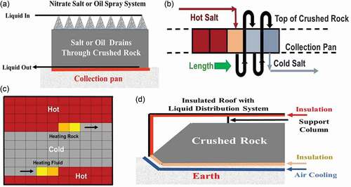
Heat is added to the crushed rock by spraying the hot heat transfer fluid over the crushed rock section by section as shown in (top). The cold heat transfer fluid is collected by the bottom collection pan to be reheated. Inert gas fills the void space between rocks. If the nitrate salt or heat transfer oil is not fully cooled by the time it reaches the collection pan, the warm fluid is pumped onto the top of the next section of crushed rock to preheat the crushed rock. A wave of hot oil or nitrate salt heats the crushed rock from left to right as shown in .
Heat is recovered by spraying cold heat transfer fluid over hot crushed rock and collecting the hot oil or nitrate salt at the bottom. There is a rock heating wave followed by a second wave to recover heat as shown in . When either wave reaches the end of the insulated structure, it starts over at the other end of the system. The design minimizes the inventory and thus the cost of the heat transfer fluid that is expensive relative to the crushed rock.
For a 100-GW.h system, the crushed rock bed in the form of a square about 250 m on a side and 20 m high. If we heat a 25 × 25-m zone at a time, the storage system would be divided into 100 zones. In traditional nitrate heat storage systems, the tank wall and insulation systems are about 40% of the capital cost. These costs are minimized by replacing the tank with an insulated building (). Hydrostatic and rock pressures on walls are eliminated by (1) gravity flow of fluid to the drain pans and (2) sloped sides of crushed rock that allow thermal expansion and contraction of the rock with temperature cycles. The building is similar to an aircraft hangar with insulated inside walls. With no horizontal stresses on the building walls or other forces on the insulation, large rock heights are possible and designed against seismic loads the same as designing against seismic loads for aircraft hangars.
There is a simplified foundation structure that can withstand the high weight loadings. From the ground upward this stucture is (1) ground, (2) foundation with air-cooling pipes to maintain constant temperature, (3) steel membrane, and (4) insulation that may contain firebrick and/or mixtures of low-conductivity materials of different sizes that are tightly compacted. The steel membrane does not see temperature transients; only the insulation above the steel membrane sees the temperature transients. The insulation is similar to a gravel road bed made of low-conductivity materials.
Rock fines will be generated over time by the expansion and contraction of the rock. The foundation insulation may create fines. Consequently, the flow of oil or nitrate salt across the insulation surface to the drains will contain fines that are removed by filters. The drain height and flow patterns may result in small amounts of liquid nitrate salt or oil at the bottom.
This system has a safety and environmental advantage relative to first- and second-generation heat storage systems. With liquids stored in tanks, there is always a concern about leaks. The liquid imposes a hydrostatic pressure on the tank wall that provides the driving force for leaks. In this system the oil or nitrate salt drains down to the collection pans. There is at the bottom at most a few centimeters of liquid oil or nitrate salt on top of the sloped floor heading toward the drains. There is no large hydrostatic pressure to push liquids out of the structure if there is a leak.
IV.C. Other Heat Storage Technologies
It is unlikely that there will be a single preferred storage technology. Different reactors couple more or less efficiently with specific heat storage technologies. Markets will be different in Texas with low-cost wind and solar versus New England with (1) limited wind and solar and (2) a massive winter heating demand. We describe an example of one other technology to provide a broader perspective of storage options. The example is cast iron for sodium-cooled reactors and CSP systems. It is an example of a storage technology that very efficiently couples to a specific type of reactor and CSP system but would not be suitable for other reactor types.
In the United States, there is a renewed interest in sodium-cooled reactors.Citation7,Citation8,Citation50 At the same time, sodium coolant is being proposedCitation51 for advanced Generation III CSP facilities with operating temperatures to 750°C. Sodium is a preferred coolant because of its excellent heat transfer properties. Sodium coolants also couple efficiently to air-Brayton combined cycle plantsCitation52 as discussed in Sec. V. Sodium-air heat exchangers for gas turbines are significantly smaller in size than most other liquid-air heat exchangers. This creates incentives for heat storage systems that use sodium as the coolant to avoid heat exchangers between (1) the sodium-cooled heat source (nuclear or CSP) and the heat storage systems and (2) the heat storage systems and the power cycle. Sodium-cooled CSP systems were first examined in the 1970s with recent renewed interest in sodium heat storage systems.Citation53,Citation54
Compared to most other coolants, sodium is more expensive and is highly flammable. That creates large incentives to minimize sodium in the storage system by adding a filler to the tank that occupies most of the volume and provides most of the heat capacity. Iron has been proposed as the filler. Early work proposed using iron balls.Citation55 More recent workCitation56,Citation57 proposes stainless steel–clad hexagonal ingots 10 to 20 m tall (), with spacing between billets for coolant flow and to provide space for thermal expansion. The cast iron occupies more than 95% of the volume to (1) minimize cost, (2) minimize safety hazards from the sodium, and (3) minimize heat transfer via the highly conductive sodium from the hot zone to the cold zone. Iron is chemically compatible with sodium; however, low-cost cast iron has impurities in it. The cast iron has stainless steel cladding to minimize slow corrosion of selected cast iron components into sodium and thus assure high-purity sodium. High purity is required for both CSP and nuclear reactor applications because of the high heat fluxes in CSP solar receivers and nuclear reactor cores. This geometry is the same geometry of fuel assemblies in sodium-cooled reactors where for neutronic and thermal-hydraulic reasons, one wants to minimize sodium between fuel assemblies. As a consequence, there is substantial understanding of hexagonal close-packed assemblies including thermal expansion effects.
Fig. 9. Hexagonal cast iron heat storage with corrosion-resistant wrapper.
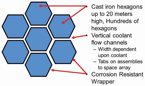
The allowable temperature ranges from 100°C to between 700°C and 900°C depending upon the iron composition. Cast iron at higher temperatures undergoes a phase transition with a large change in volume that would likely cause major design challenges; thus, operating temperatures should be held below this transition temperature. The phase change temperature for cast iron (iron with carbon) is at 727°C. With pure iron the phase change occurs at 917°C.
If one uses a gigawatt hour as a measure of storage and assumes a 100 K hot-to-cold temperature swing, one requires 80 000 tonnes/GW.h of iron (80 kg/GW.h). Steel prices are typically near $500/tonne when ordered in quantity implying iron costs near $40/GW.h of heat storage. If the temperature difference between hot and cold is increased to 300°C, heat storage costs are reduced by a factor of 3. Tripling the hot-cold temperature range in storage cuts storage costs by a factor of 3 or more, with the potential to meet the DOE cost goal for heat storage of $15/kW.h, excluding other system costs. Such costs are viable for daily heat storage but not for weekly heat storage.
shows one possible arrangement of heat storage tanks between the reactor or CSP system and the power block. A series of heat storage tanks is used to minimize the hot-cold interface between hot and cold sodium. There is the option to choose a power cycle that results in very low temperatures of the sodium sent back to the reactor or CSP system. This minimizes the cost of heat storage by maximizing the hot-cold sodium temperature change. If the cold sodium temperature is below the allowable inlet sodium temperature for the reactor or CSP system, hot sodium can be mixed with cold sodium to match required sodium inlet temperature requirements.
Fig. 10. Schematic tank system for sodium reactor or CSP system.
V. POWER CYCLES
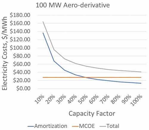
The alternative system design requires changes in the power cycle if nuclear power is to replace the gas turbine in providing low-cost dispatchable electricity. The power cycle may be operating only part of the time. Total generating capacity may be several times base-load nuclear plant output. The technical goal is a power cycle with the ability to rapidly start and vary power levels to match demand. The economic goal is low capital costs—substantially below conventional gas turbines or batteries and other electricity storage systems. As the power cycle is used fewer hours per year, the power block capital costs become a larger fraction of the total cost of electricity. The cost of energy becomes a smaller fraction of the total cost of electricity. This economic relationship is shown in for a simple gas turbineCitation4 used to meet variable electricity demand but applies to all electricity-generating technologies used to meet variable electricity demand. The practical implication is that the economics favors somewhat less efficient power cycles with lower capital costs. The power cycles must be modified for the different requirements.
Fig. 11. Electricity costs versus capacity factor for natural gas peaking turbine (courtesy of Pintail Power LLC).
We describe herein three power cycles that are under development (1) with capital cost goals to be below existing combined cycle gas turbines for peak electricity production and (2) designed for variable output. The Electric Power Research InstituteCitation4 (EPRI) is examining simplified steam cycles () based on those used in gas-fired combined cycle plants and CSP plants. Such designs use existing off-the-shelf commercial technologies, are applicable to multiple Generation IV (Gen-IV) reactors with heat storage, and use the common supply chain associated with fossil and solar systems to minimize front-end capital costs. The higher temperatures allow superheated steam with major steam cycle simplifications (no wet-steam moisture removal systems, etc.) and cost reductions in the power cycle.
Fig. 12. EPRI simplified steam cycle for advanced Gen-IV plants.
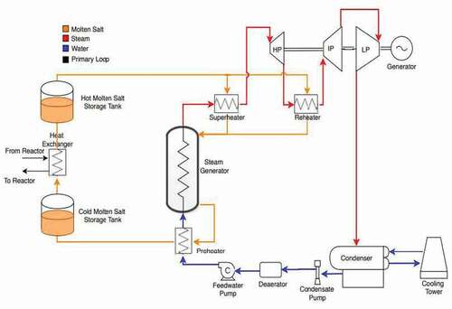
Pintail Power LLC (CitationRefs. 58, Citation59, and Citation60) is developing a low-capital-cost power cycle as shown in that includes nitrate salt heat storage. This system was originally designed for markets with large quantities of low-price electricity. At times of low electricity prices, electricity is used to heat nitrate salt to high temperatures. At times of high prices, stored heat produces electricity that is sold to the grid. The same power cycle couples to any nuclear system using nitrate storage.
Fig. 13. Pintail salt liquid-salt combined cycle.TM
At first glance, this power cycle looks similar to the traditional combined cycle plant, but its performance and cost structure are radically different: The steam cycle output is two to three times the output of the gas turbine. In a conventional combined cycle plant, two-thirds of the electricity is produced by the gas turbine with a third from the steam cycle. In this system water is evaporated using energy stored in molten salt, while the gas turbine exhaust is used to (1) superheat the steam for a single, nonreheat steam cycle and (2) then preheat feedwater. The high steam temperature is needed primarily for minimizing the moisture content at the steam turbine exhaust. This design change avoids complicated steam cycles and associated capital costs with multiple feedwater preheaters, steam separators, and steam turbines. Much of the heat input is from liquid hot salt to boil water whereas in a conventional combined cycle gas turbine, warm atmospheric-pressure air from the turbine exhaust is used to boil the water. The heat transfer rate between hot salt and boiling water is extremely high resulting in small heat exchangers. In contrast, the heat transfer rate between warm air from the gas turbine and boiling water in a conventional combined cycle plant is low resulting in the large size of heat recovery steam generators (HRSGs). Those heat exchangers are the largest physical structure in a combined cycle plant. At the same time, the types of equipment remain the same, and the existing supply chains can provide the new power block.
This system uses a combustible fuel with a remarkable heat rate. The combustible heat rate of a simple gas turbine, combined cycle turbine, and this cycle are 9300, 6000, and under 4500 kJ/kW.h, respectively. In a low-carbon world, the use of fossil fuels will be limited, or there may be a carbon tax. The available combustible fuels may be low-carbon hydrogen or biofuels, with potentially higher costs. This creates large economic incentives for a more fuel-efficient, lower-cost gas turbine cycle such as the Pintail Power cycle that includes heat input via salt storage.
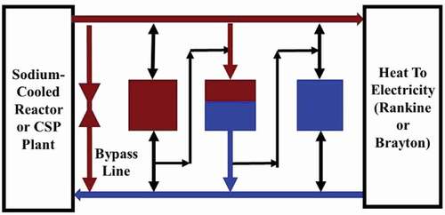
A third class of power cycles is Nuclear Air Brayton Combined Cycles (NACCs) where the heat from the reactor or heat storage system goes to the gas turbine.Citation52 shows one NACC design using existing gas turbine technology. The technology is available, but the system does not use existing off-the-shelf commercial equipment. The black lines show the airflow during normal operations. Air is filtered, compressed, heated in heat exchanger 1 (HX1), goes through turbine 1, is reheated in heat exchanger 2 (HX2), goes through turbine 2, is reheated in heat exchanger 3 (HX3), goes through turbine 3, and exits to the HRSG and up the stack. The steam produced in the HRSG can be sent to industry or used to produce electricity. In each heat exchanger, heat from a nuclear plant or heat storage system is transferred to the compressed air. The heat transfer fluid may be a liquid salt, sodium, or other fluid. This is a gas turbine that can be shut down and started up on stored heat like the traditional gas turbine while the reactor operates at full capacity.
Fig. 14. Nuclear air Brayton cycle with thermodynamic topping cycle and heat storage.
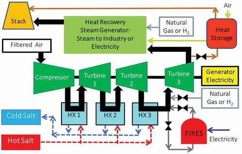
For peak electricity production, the hot air exiting HX3 can be further heated by injecting natural gas, biofuels, or hydrogen into the warm compressed air where fuel combustion raises its temperature to 1527°C, similar to the peak temperatures in a modern gas turbine with actively cooled blades. The incremental heat-to-electricity efficiency in burning a combustible fuel in the thermodynamic topping cycle is 74% to 75%, that is, 100% times the added electricity from burning the combustible fuel divided by the added heat from burning the combustible fuel. The incremental heat-to-electricity efficiency is far above any other heat engine. In a low-carbon world, the likely combustible fuels will be hydrogen or biofuels, which are premium fuels with premium prices and large incentives for their efficient conversion of heat to electricity. Lower-cost nuclear heat provides heat input at lower heat-to-electricity efficiency with the more expensive fuel converting heat to electricity at a much higher efficiency. The peak power output can be several times the base-load power output.
The second storage technologyCitation61 that can be incorporated into NACC is Firebrick Resistance Heated Energy Storage (FIRES) where at times of low electricity prices, firebrick is electrically-resistance heated to high temperatures. At times of high electricity prices, gas exiting from HX-3 is sent through FIRES before going to turbine 3. Stored high-temperature heat replaces the use of a combustible fuel for the thermodynamic topping cycle.
Last, several groups are developing heat storage systems between the Brayton cycle and the HRSG. At times of low electricity prices, most of the hot air from the Brayton cycle is sent to a recuperator filled with firebrick, crushed rock, or special concrete and then is sent to the exhaust stack. The recuperator is heated by the exhaust gas from the gas turbine. At times of high electricity prices, cold air is blown through the hot recuperator, is heated, and is sent to the HRSG. At the same time added hot air comes from the Brayton cycle, so the peak power output of the HRSG is increased. This increase in power input is separate and independent of any increase from operating the thermodynamic topping cycle. Several of these systems are at the pilot plant stage of development for natural gas–fired gas turbine combined cycle systems.
All of the above cycles are built on existing power cycle technology. Work is underway to develop supercritical carbon dioxide cycles that may have significantly lower capital costs. If these are commercialized, they create a new set of options.
There is a second dimension associated with these power cycles that is relatively unexplored. The ramping rate (speed to change electricity output) of traditional nuclear and fossil power blocks is usually limited by the ramping rate of the heat source. If one has stored heat, the rate of heat delivery to the power cycle is controlled by the pump moving hot salt from storage into the power block. Pump speeds can be changed very rapidly. This creates the option for power blocks with much faster ramping speeds than traditional systems. Such fast ramping rates have the potential for these systems to replace pumped hydropower, batteries, and other technologies that are traditionally used to provide fast response. It also may dramatically reduce the need for spinning reserve in the traditional sense to pick up lost electrical load if a major power generator is shut down for any reason.
VI. NUCLEAR ISLANDS
The original nuclear plant designs followed those of coal plants, that is, tight integration of the heat source with the turbine generators. Events such as the Three Mile Island accident and the September 11 terrorist attack added safety and security requirements. Regulations evolved over decades. These changes have created incentives to separate the nuclear reactor plant from the nonnuclear balance of plant by heat storage. The nuclear island follows nuclear standards and regulations with the balance of plant following standard industrial practice. There are several factors that are expected to change designs and lower costs,Citation4 primarily by reducing requirements associated with the nuclear island:
Reduced power system interface: With existing nuclear power plants, reactor operations are directly coupled to the operation of the electrical grid. If the grid fails for any reason, it results in reactor shutdown. Varying electricity demand results in varying reactor power output. Any failures in the power block imply rapid changes in reactor operations. With heat storage, the reactor interface is heating cold salt or another fluid and sending the salt or other fluid to a second tank. This is a radical simplification of the interface between the reactor and the outside world. This allows simplification of the reactor design, operations, and safety, including nuclear regulatory concerns about grid impacts on reactor operations, of which there are none.
Security: In current plants, much of the balance of plant is within the security boundary with major cost implications. Physical security boundaries are much larger than just the reactor and its safety systems. Security forces are larger to protect the larger footprint and address access by a much larger number of workers that enter the plant to work on nonnuclear systems in the security area. Nuclear security increases the cost of maintenance on nonnuclear systems because of access constraints.
Nuclear quality bleed over: Nuclear quality standards bleed over into secondary systems because of the difficulty in defining the boundaries of different systems. If the boundary is a pipe of cold salt coming into the nuclear plant and a pipe of hot salt leaving the nuclear plant, the boundary is well defined.
Competitive bidding: If one has a separate nonnuclear power block, the design and construction of that part of the plant can be done by any company or consortium that does nonnuclear industrial projects. The experience from other industrial projects is directly applicable. This also applies to spare parts and maintenance. This is a highly competitive industry with many suppliers that drives down costs versus the relatively small number of companies that build and maintain nuclear facilities. Separate from these considerations, many of the heat storage technologies and power block options may be identical for nuclear and CSP systems (see Sec. IX) creating additional competitive forces to drive down costs.
Several advanced reactor designsCitation7–9 have adopted the separate nuclear island from the power block by storage and reported large decreases in the quantities of concrete (TerraPower Natrium reactor) and other materials required for the nuclear plant. This is an area where change is occurring rapidly, but there is little public information in the literature because of proprietary considerations and restrictions on release of data associated with security requirements.
VII. INSTITUTIONAL AND REGULATORY CONSIDERATIONS
VII.A. Resilience
Adding heat storage and associated peak power systems increases power system resilience. The reactor is no longer directly tied to the electricity grid. The reactor does not shut down if the grid fails for any reason. Similarly, the impacts of reactor shutdown on electricity to the grid do not occur for hours or days until heat storage is depleted, which provides time for grid operators to decide what other units to bring online to meet electricity demand. The power block can be designed for rapid response to electricity grid needs, faster than a turbine generator tied to a nuclear reactor. Heat storage provides hours to 1 week of energy storage: a super battery.
System resilience has been defined by the Federal Electric Regulatory CommissionCitation62 as “the ability to withstand and reduce the magnitude and duration of disruptive events, which includes the capability to anticipate, adsorb, adapt to, and/or recover from disruptive events.” Work by GreeneCitation4,Citation63–66 has defined system resilience in terms of the following six defining functional capabilities; in italics is the impact of adding heat storage that separates the reactor from the power block:
Robust real/reactive load-following and flexible operation capability. Not needed because flexible operation achieved by heat storage and isolated power block.
Immunity to damage from external events (including grid anomalies). External grid events do not impact reactor because reactor isolated from the grid by heat storage. Does not impact other implications of other external events.
Ability to avoid plant shutdown (reactor scram) in response to grid anomalies. External grid events do not impact reactor because reactor isolated from the grid by heat storage.
Ability to operate in island mode (i.e., without connection to off-site transmission load and electric power supply). Reactor connected to heat storage and effectively always operating in island mode.
Unlimited independent safe shutdown cooling capacity (i.e., requiring no off-site or resupply of diesel fuel from off-site). New plant system design may have no impact on these requirements.
Independent self-cranking black start capability (i.e., the ability to start with no off-site cranking power supply from the grid). Black-start capabilities can be designed into the isolated power block using heat storage as the energy source.
The alternative design with heat storage and the decoupling of the reactor from the power block via heat storage improves five of those functional capabilities while reducing reactor requirements; only independent safe shutdown cooling is not changed. What may ultimately be equally important is that heat storage enables designs of power blocks not constrained by the ability to ramp up or down the reactor power. Rates of changes in heat delivered to the power block are only limited by the pump moving hot salt or other fluid from storage into the power block. This creates the option for power blocks with much faster ramping speeds that supports grid operations. We are not aware of any studies that have evaluated the limits of ramping speeds for these technologies and the implications for the electricity grid.
VII.B. Licensing
The historical licensing structure in the United States has been prescriptive. The new licensing structure is risk based.Citation67–69 This change in licensing is a practical requirement if there are to be major changes in the basic design of nuclear power plants. The legal basis for such changes is in place, but there is limited experience in the new licensing basis for new plants.
Licensing will be reduced with the new plant design. A significant fraction of the off-normal events associated with transients are from the power cycle, either internally within the power cycle or transients that started from the electricity grid. Heat storage eliminates these transients that can impact the reactor operations. Similarly, the licensing associated with security is simplified: There is no power block in the security zone resulting in a much smaller security zone with far fewer people that require access. Last, there is a clear dividing line between nuclear and nonnuclear systems.
VIII. ECONOMICS AND BUSINESS MODELS
VIII.A. Electricity Production
The new plant design impacts revenue and costs. In many markets the revenue for the first plants will increase by more than 50%; however, each additional plant will alter the electricity markets, so revenue gains decrease as added plants with added storage enter the market.
There are major changes in how one thinks about the most economic design for a specific market. With traditional nuclear and fossil plants, there is a direct coupling between energy generation and electricity output. When the heat output is 100% of capacity, the electric generator is operating at 100% capacity. With the addition of large-scale heat storage, energy generation is decoupled from peak power output. This is similar to the design of large hydroelectric dams. The dam is built with the capability of producing X amount of energy over some period of time based on river flow and the height of the dam. The power house with hydroelectric turbines is sized to meet some peak electricity demand (kilowatts). In the context of a nuclear power plant, a much larger fraction of the total plant cost (heat storage and power block) is conventional construction with its much more predictable cost and schedule. The cost, developmental risks, and schedule risks are reduced. Heat storage and the power block may be identical for CSP (see the Appendix) and nuclear plants with the same supply chain.
VIII.B. Business Models for Nuclear Cogeneration of Heat and Electricity
In the United States, electricity is less than 18% of total energy consumption by the customer (residential, commercial, industrial, transport). The rest of the demand is for heat. The industrial heat demand is more than twice the total U.S. electricity production. There are large economic incentives for nuclear cogeneration with large-scale heat storage to enable variable electricity to the grid by varying heat demand. Heat storage is an enabling technology because it partly decouples in time industrial heat demand with electricity demand. The requirement is that reactor output equal heat demand plus electricity demand when averaged over days to 1 week. Many heat customers can adjust their production schedule and thus heat demand over such a period of time.
While the economics are clear, what is the business model? If one has a large industrial facility with a massive demand for heat, the business model is simple. The industrial customer owns the reactors and internally optimizes heat for internal uses and external electricity sales to maximize net revenue. Several studies evaluated high-temperature heat markets for nuclear cogeneration.Citation70,Citation71 In addition, there have been multiple business studies for specific applicationsCitation72–75 using this model.
The more complicated and less understood case is where one has a set of reactors selling electricity and heat to multiple customers. Developing the business case has been a major barrier to the deployment of conventional cogeneration. The problem is how to align the business interests of multiple businesses. Industrial customers with large capital investments do not want to be hostage to the owner of the nuclear power plant raising the cost of heat to maximize short-term profits or sell electricity rather than heat if the price of electricity increases significantly. This is a contractual relationship that may extend over many decades. Over such a period of time, there can be massive changes in the business environment and the demand for heat or electricity. There have been many business studies of cogenerationCitation4,Citation30 where extra investment improves energy efficiency but economic efficiency is not assured by energy efficiency. There are difficulties in serving two customers. The features of the optimized system for a pair of products is very sensitive to economic variables. Industrial customers do not want to be captive to another business, i.e., the “hold-up” problem. Long-term contracts have limited value. For these and other reasons, cogeneration scale has always fallen far short of engineering calculations of the value. There are in this case two differences that may reduce business barriers to cogeneration:
Heat storage: Traditional nuclear cogeneration had a fixed maximum output that implied any increase in heat demand on a second-by-second basis implied less electricity to the grid. With storage, the requirement is to match production with industrial heat demand and electricity over a period of hours or days. Short-term peak heat or electricity demands can be met. There is the option to schedule industrial production to maximize total revenue from heat and electricity. There is the additional degree of freedom in operations.
Goal of a low-carbon economy: This goal takes away low-cost stored energy in the form of tanks of oil, natural gas, and coal from multiple suppliers.
Historically, most cogeneration systems with many customers have been municipal systems where the city had the goals to provide economic electricity and heat to industrial customers as part of its industrial development strategy to increase taxable industrial property and support employment. The revenue benefits to the city are in the form of added industrial property on tax rolls and employment. This aligns the long-term economic interests of the city with the industrial and commercial customers. There is a variety of other business models from industrial coops to regulated utilities to totally private enterprises, but the full implications have not been explored.
IX. CONCLUSIONS
The electricity market is rapidly changing. Those changes require a low-carbon replacement for (1) the gas turbine with its capability to provide economic variable electricity to the grid and (2) fossil fuel heat to industry. Nuclear, wind, and solar have high capital costs and low operating costs creating large economic incentives to operate at maximum output. That can be accomplished by matching energy production with demand using storage. Heat storage that couples to nuclear reactors is an order-of-magnitude cheaper than electricity storage (batteries, CAES, pumped hydroelectricity) that couples to wind and PV. The lower costs of heat storage relative to electricity (work) storage create large economic incentives to use heat storage to match energy production with demand, thus creating a competitive advantage for nuclear power because it produces heat.
Recent nuclear electricity studiesCitation76 provide some quantification of benefits. However, significant additional work is required. The potential for very low cost heat storage coupled with the low cost of converting electricity to heat also implies incentives to dump low-price electricity into the same heat storage systems creating nuclear power plants that buy and sell electricity. Such systems will improve the economics of nuclear, wind, and solar relative to other technologies.
Second, nuclear plant safety and security requirements have changed in the last 50 years, suggesting that a lower-cost plant layout may be to separate the nuclear island from the power block with large-scale heat storage. This isolates the nuclear reactor from the outside world and thus reduces requirements for the nuclear systems with reductions in capital and operating costs. It also implies major changes in the power block. Historically, the performance and capital costs of the power block have been constrained by the characteristics of the heat source, i.e., nuclear, fossil, or CSP. With heat storage, change in heat input into the power block is controlled by a variable-speed oil or nitrate salt pump. The rate of change in heat input rates can be an order of magnitude faster; the implications for the electricity grid are mostly unexplored.
Last, the enabling heat storage and power cycle technologies are rapidly advancing. These areas are relatively unexplored because there was no incentive to develop these technologies until energy markets and nuclear plant requirements changed. The basic features of the proposed redesign of nuclear systems are defined, but much work remains to understand the full implications of these changes.
Acknowledgments
The author would like to thank for their support the Idaho National Laboratory National Universities Consortium Program under DOE Idaho Operations contract DE-AC07-05ID14517 and the Shanghai Institute of Applied Physics of the Chinese Academy of Sciences.
References
- C. FORSBERG et al., “Light Water Reactor Heat Storage for Peak Power and Increased Revenue: Focused Workshop on Near-Term Options,” MIT-ANP-TR-170, Massachusetts Institute of Technology (July 2017); http://energy.mit.edu/publication/light-water-reactor-heat-storage-peak-power-increased-revenue/ ( current as of Jan. 1, 2021).
- C. W. FORSBERG, “Variable and Assured Peak Electricity from Base-Load Light-Water Reactors with Heat Storage and Auxiliary Combustible Fuels,” Nucl. Technol., 205, 3, 377 (2019); https://doi.org/https://doi.org/10.1080/00295450.2018.1518555.
- C. W. FORSBERG et al., “Heat Storage Coupled to Generation IV Reactors for Variable Electricity from Base-Load Reactors: Workshop Proceedings. Changing Markets, Technology, Nuclear-Renewables Integration and Synergisms with Solar Thermal Power Systems,” MIT-ANP-TR-185, Center for Advanced Nuclear Energy, Massachusetts Institute of Technology, INL/EXT-19-54909, Idaho National Laboratory (2019); https://osti.gov/biblio/1575201 ( 2019) (current as of Jan. 1, 2021).
- C. FORSBERG, P. SABBARWALL, and A. SOWDER, “Separating Nuclear Reactors from the Power Block with Heat Storage: A New Power Plant Design Paradigm,” MIT-ANP-TR-189, Center for Advanced Nuclear Energy, Massachusetts Institute of Technology; https://www.osti.gov/biblio/1768046 (Nov. 2020) (current as of Jan. 1, 2021).
- J. BUONGIORNO et al., “Future of Nuclear Power in a Carbon Constrained World,” Massachusetts Institute of Technology (2018); http://energy.mit.edu/research/future-nuclear-energy-carbon-constrained-world/ ( current as of Jan. 1, 2021).
- P. EASH-GATES et al., “Sources of Cost Overrun in Nuclear Power Plant Construction Call for a New Approach to Engineering Design,” Joule, 4, 11, 2348 (Nov. 2020).
- P. HEZJLAR, “Traveling Wave Reactor (TWR),” Encyclopedia of Nuclear Energy, pp. 643–656 (2021); https://doi.org/https://doi.org/10.1016/B978-0-12-409548-9.12213-4; https://www.terrapower.com/ ( current as of Jan. 1, 2021).
- NATRIUM website; https://natriumpower.com/ (2020) ( current as of Jan. 1, 2021).
- Moltex Energy website; https://www.moltexenergy.com/ (2020) (current as of Jan. 1, 2021).
- R. SCHMALENSEE et al., “The Future of Solar Energy—An Interdisciplinary MIT Study,” Massachusetts Institute of Technology (2015); http://energy.mit.edu/research/future-solar-energy/ ( current as of Jan. 1, 2021).
- V. SIVARAM and S. KANN, “Solar Power Needs a More Ambitious Cost Target,” Nat. Energy, 1, 16036 (Apr. 2016); https://www.nature.com/articles/nenergy201636.pdf ( current as of Jan. 1, 2021).
- J. BUSHNELL and K. NOVAN, “Setting with the Sun: The Impacts of Renewable Energy on Wholesale Power Markets,” UC Davis Energy Economics Program, DEEP WP 020 (May 2018); http://deep.ucdavis.edu/uploads/5/6/8/7/56877229/deep_wp020.pdf ( current as of Jan. 1, 2021).
- A. D. MILLS et al., “Impact of Wind, Solar, and Other Factors on Wholesale Power Prices: An Historical Analysis—2008 Through 2017,” Lawrence Berkeley National Laboratory (Nov. 2019); https://emp.lbl.gov/publications/impact-wind-solar-and-other-factors ( current as of Jan. 1, 2021).
- N. A. SEPULVEDA et al., “The Role of Firm Low-Carbon Electricity Resources in Deep Decarbonization of Power Generation,” Joule, 2, 11, 2403 (Nov. 2018); https://doi.org/https://doi.org/10.1016/j.joule.2018.08.006.
- “Energy Flow Charts,” Lawrence Livermore National Laboratory; https://flowcharts.llnl.gov/content/assets/images/energy/us/Energy_US_2019.png ( current as of Jan. 1, 2021).
- C. FORSBERG and S. BRAGG-SITTON, “Maximizing Clean Energy Utilization: Integrating Nuclear and Renewable Technologies to Support Variable Electricity, Heat and Hydrogen Demands,” The Bridge, U.S. National Academy of Engineering (Fall 2020).
- C. FORSBERG, “Massachusetts Institute of Technology: Coupling Heat Storage to Base Load Nuclear Reactors,” Chap. 7, in “Flexible Nuclear Energy for Clean Energy Systems,” NREL/TP-6A50-77088, National Renewable Energy Laboratory; (Sep. 2020) https://www.nrel.gov/docs/fy20osti/77088.pdf ( current as of Jan. 1, 2021).
- “Electricity Explained—Factors Affecting Electricity Prices,” U.S. Energy Information Agency; https://www.eia.gov/energyexplained/electricity/prices-and-factors-affecting-prices.php ( current as of Jan. 1, 2021).
- SolarPACES website; https://www.solarpaces.org/ ( current as ofJan. 1, 2021).
- “Concentrating Solar Power Projects,” U.S. Department of Energy, Office of Energy Efficiency and Renewable Energy; https://solarpaces.nrel.gov/ ( current as of June 30, 2020).
- Proc. 2nd Int. Workshop on Carnot Batteries 2020, University Stuttart, September 15–16, 2020; https://iwcb2020.besl-eventservice.de/ ( current as of June 30, 2020).
- MALTA website; https://www.maltainc.com/ (2020) ( current as of Jan. 1, 2021).
- W. D. STEINMANN, “Thermo-Mechanical Concepts for Bulk Energy Storage,” Renewable Sustainable Energy Rev., 75, 205 (Aug. 2017); https://doi.org/https://doi.org/10.1016/j.rser.2016.10.065.
- R. B. LAUGHLIN, “Pump Thermal Grid Storage with Heat Exchangers,” J. Renewable and Sustainable Energy, 9, 4, 044103 (2017); https://doi.org/https://doi.org/10.1063/1.4994054.
- W. D. STEINMANN, H. JOCKENHOFER, and D. BAUER, “Thermodynamic Analysis of High-Temperature Carnot Battery Concepts,” Energy Technology (2019); https://doi.org/https://doi.org/10.1002/ente.201900895.
- D. S. MALLAPRAGADA et al., “Can Industrial-Scale Solar Hydrogen Supplied from Commodity Technologies Be Cost Competitive by 2030?” Cell Reports Phys. Sci., 1, 9, 100174 (2020); https://doi.org/https://doi.org/10.1016/j.xcrp.2020.100174.
- “Missing Link to a Livable Climate: How Hydrogen-Enabled Synthetic Fuels Can Help Deliver the Paris Goals,” Lucid Catalyst (2020); https://www.lucidcatalyst.com/hydrogen-report ( current as of Jan. 1, 2021).
- M. F. RUTH et al., “The Technical and Economic Potential for the H2@Scale Concept Within the United States,” NREL/TP-6A20-77610, National Renewable Energy Laboratory (Oct. 2020); https://www.nrel.gov/docs/fy21osti/77610.pdf ( current as of Jan. 1, 2021).
- C. FORSBERG et al., “Replacing Liquid Fossil Fuels and Hydrocarbon Chemical Feeds406tocks with Liquid Biofuels from Large-Scale Nuclear Biorefineries,” Appl. Energy, 298, 117525, (Sep. 15, 2021).
- P. JOSKOW and D. R. JONES, “The Simple Economics of Industrial Cogeneration,” Energy J., 4, 1, 1 (1983); https://doi.org/https://doi.org/10.5547/0195-6574-EJ-Vol4-No1-1.
- “Energy Storage Grand Challenge: Energy Storage Market Report,” NREL/TP-5400-78461; DOE/GO-102020-5497, U.S. Deparment of Energy (Dec. 2020) ( current as of Jan. 1, 2021).
- C. FORSBERG, S. BRICK, and G. HARATYK, “Coupling Heat Storage to Nuclear Reactors for Variable Electricity Output with Base-Load Reactor Operation,” Electricity J., 31, 3, 23 (2018); https://doi.org/https://doi.org/10.1016/j.tej.2018.03.008.
- “Energy Storage Cost Analysis: 2017 Methods and Results,” Electric Power Research Institute (2017); https://www.epri.com/research/products/000000003002012046 ( current as of Jan. 1, 2021).
- “2020 Grid Energy Storage Technology Cost and Performance Assessment,” DOE/PA-0204, U.S. Department of Energy (Dec. 2020).
- “Energy Storage Grand Challenge Roadmap,” DOE/PA-0022, U.S. Department of Energy (Dec. 2020).
- “Raccoon Mountain,” Tennesse Valley Authority; https://www.tva.com/energy/our-power-system/hydroelectric/raccoon-mountain (current as of Jan. 1, 2021).
- M. CHAANAOUI, S. VAUDREUIL, and T. BOUAHMIDI, “Benchmark of Concentrating Solar Power Plants: Historical, Current, and Future Technical and Economic Development,” Procedia Computer Sci., 83, 782 (2016); https://doi.org/https://doi.org/10.1016/j.procs.2016.04.167.
- A. BONK et al., “Thermal Stability of Solar Salt at 650°C—A Deep Dive into Molten Nitrate Salt Chemistry,” Proc. Int. Conf. SolarPACES, Albuquerque, New Mexico, September 29–October 2, 2020.
- A. BONK et al., “Solar Salt—Pushing an Old Material for Energy Storage to a New Limit,” Appl. Energy, 262, 114535 (2020); https://doi.org/https://doi.org/10.1016/j.apenergy.2020.114535.
- V. NUNES et al., “Molten Salts as Engineering Fluids – A Review: Part I. Molten Alkali Nitrates,” Appl. Energy, 183, 603 (2016).
- E. BLANDFORD et al., “Kairos Power Thermal Hydraulics Research and Development,” Nucl. Eng. Des., 364, 110636 (2020); https://doi.org/https://doi.org/10.1016/j.nucengdes.2020.110636.
- C. FORSBERG et al., “Fusion Blankets and Fluoride-Salt-Cooled High-Temperature Reactors with Flibe Salt Coolant: Common Challenges, Tritium Control, and Opportunities for Synergistic Development Strategies Between Fission, Fusion and Solar Salt Technologies,” Nucl. Technol., 206, 11, 1778 ( 2020); https://doi.org/https://doi.org/10.1080/00295450.2019.1691400.
- M. MEHOS et al., “Concentrated Solar Power Gen3 Demonstration Roadmap,” NREL/TP-5500-67464, National Renewable Energy Laboratory (Jan. 2017); https://www.nrel.gov/docs/fy17osti/67464.pdf ( current as of Jan. 1, 2021).
- Y. ZHAO and J. VIDAL, “Potential Scalability of a Cost Effective Purification Method for MgCl2-Containing Salts for Next Generation Concentrating Solar Power Technologies,” Sol. Energy Mater. Sol. Cells, 215, 110663 (2020); https://doi.org/https://doi.org/10.1016/j.solmat.2020.110663.
- W. DING, A. BONK, and T. BAUER, “Corrosion Behavior of Metallic Alloys in Molten Chloride Salts for Thermal Energy Storage in Concentrated Solar Power Plants: A Review,” Front. Chem. Sci. Eng., 12, 3, 564 (Mar. 2018); https://doi.org/https://doi.org/10.1007/s11705-018-1720-0.
- A. C. CALDWELL, G. ITSKOS, and K. H. SANDHAGE, “Air-Stable Molten Salts and Corrosion-Resistance Containment for High-Temperature Thermal Energy Storage,” Proc. Int. Conf. SolarPACES, Albuquerque, New Mexico, September 29–October 2, 2020.
- K. F. AMUDA and R. M. FIELD, “Proposed Heat Storage and Recovery Facility Designs for Korean Nuclear Power Plants Using Ultra Large Floating Barge,” Transactions of the Korean Nuclear Society Autumn Meeting, Goyang, Korea, October 23–25, 2019.
- C. ODENTHAL et al., “Experimental and Numerical Investigation of a 4 MWh High Temperature Molten Salt Thermocline Storage System with Filler,” Proc. Int. Conf. SolarPACES, Daegu, Korea, October 1–4, 2019.
- C. FORSBERG and A. S. ALJEFRI, “100-Gigawatt-Hour Crushed-Rock Heat Storage for CSP and Nuclear,” Proc. Int. Conf. SolarPACES, Albuquerque, New Mexico, September 29–October 2, 2020.
- P. McDANIEL and C. FORSBERG, “A Sodium-cooled Thermal Spectrum Fission Battery,” 28th International Conference on Nuclear Engineering, ICONE2021-65765, (Virtual) August 4-6, 2021.
- C. S. TURCHI et al., “Molten Salt Versus Liquid Sodium Receiver Selection Using Analytic Hierarchy Process,” Proc. Int. Conf. SolarPACES, Albuquerque, New Mexico, September 29–October 2, 2020.
- C. W. FORSBERG, P. J. McDANIEL, and B. ZOHURI, “Nuclear Air-Brayton Power Cycles with Thermodynamic Topping Cycles, Assured Peaking Capacity and Heat Storage for Variable Electricity and Heat,” Nucl. Technol., 207, 4, 543 (2021); https://doi.org/https://doi.org/10.1080/00295450.2020.1785793.
- T. WETZEL et al., “Liquid Metal Technology for Concentrated Solar Power Systems: Contributions by the German Research Program (Review),” AIMS Energy, 2, 1, 89 (Mar. 2014); https://doi.org/https://doi.org/10.3934/energy.2014.1.89.
- K. NIEDERMEIER et al., “Assessment of Thermal Energy Storage Options in Sodium-Based CSP Plant,” Appl. Thermal Eng., 107, 386 (2016); https://doi.org/https://doi.org/10.1016/j.applthermaleng.2016.06.152.
- B. D.POMEROY and R. M.SALEMME, “Alternative Configurations for Sodium-Cooled Solar Thermal Power Plants,” IEEE Transactions on Power Apparatus and Systems, Vol. PAS-99, No. 5, p. 2012, Institute of Electrical and Electronics Engineers (1980); https://doi.org/https://doi.org/10.1109/TPAS.1980.319829.
- C. FORSBERG, “Sodium-Steel Heat Storage for Variable Energy Output from Nuclear and Solar Power Systems,” Trans. Am. Nucl. Soc., 119, 935 (2018).
- C. FORSBERG and P. SABHARWALL, “Heat Storage Options for Sodium, Salt and Helium Cooled Reactors to Enable Variable Electricity to the Grid and Heat to Industry with Base-Load Operations,” ANP-TR-181, Center for Advanced Nuclear Energy, Massachusetts Institute of Technology, INL/EXT-18-51329, Idaho National Laboratory (2018).
- W. M. CONLON and M. J. VENETOS, “Another Gas Turbine Decarbonization Path: Adding Energy Storage to the Combined Cycle,” Mech. Eng., 143, 1, 64 (Dec./Jan. 2020/2021); https://doi.org/https://doi.org/10.1115/1.2021-JAN10.
- W. CONLON, “Decarbonizing with Energy Storage Combined Cycles,” POWER Magazine, 36 (Dec. 2019).
- W. CONLON, “Dispatchable Combined Cycle Power Plant,” U.S. Patent 10,113,535 (2018).
- D. STACK, “Development of High-Temperature Firebrick Resistance Heated Energy Storage (FIRES) Using Doped Ceramic Heating System,” PhD Thesis, Massachusetts Institute of Technology (Dec. 2020).
- “Grid Resilience in Regional Transmission Organizations and Independent System Operators,” Docket No. AD18-7-000, 162 FERC, 61,012, Federal Energy Regulatory Commission (Jan. 8, 2018) ( “Grid Resilience Order”).
- S. R. GREENE, “Are Current U.S. Nuclear Power Plants Grid Resilience Assets?” Nucl. Technol., 202, 1, 1 (2018); https://doi.org/https://doi.org/10.1080/00295450.2018.1432966.
- S. R. GREENE, “Nuclear Power: Black Sky Liability or Black Sky Asset?” Int. J. Nucl. Secur., 2, 3, 3 (2016); https://doi.org/https://doi.org/10.7290/V78913SR.
- S. R. GREENE, “The Key Attributes, Functional Requirements, and Design Features of Resilient Nuclear Power Plants (rNPPs),” Nucl. Technol., 204, 2, 131 (2018); https://doi.org/https://doi.org/10.1080/00295450.2018.1480213.
- S. R. GREENE, “Enhancing Electric Grid, Critical Infrastructure, and Societal Resilience with Resilient Nuclear Power Plants (rNPPs),” Nucl. Technol., 205, 3, 397 (2018); https://doi.org/https://doi.org/10.1080/00295450.2018.1505357.
- Regulatory Guide 1.233, “Guidance for Technology Inclusive, Risk Informed, and Performance Based Methodology to Inform the Licensing Basis and Content of Applications for Licenses, Certifications and Approvals for Non-Light-Water Reactors,” U.S. Nuclear Regulatory Commission (June 2020).
- “Risk-Informed Performance-Based Technology Inclusive Guidance for Non-Light Water Reactor Licensing Basis Development,” Technical Report 18-04, Nuclear Energy Institute (Aug. 2019).
- R. A. MESERVE, “Regulatory Innovation to Support Advanced Reactors,” Bridge, 50, 3 ( Fall 2020).
- “High Temperature Gas-Cooled Reactor Projected Markets and Preliminary Economics,” INL/EXT-10-19037, Rev. 1, Idaho National Laboratory (Aug. 2011); https://inldigitallibrary.inl.gov/sites/sti/sti/4633195.pdf (current as of Jan. 1, 2021).
- J. CONEFAL and D. RACKIEWICZ, “Survey of HTGR Process Energy Applications,” MPR-3181, MPR Associates, Inc. (May 2008); https://art.inl.gov/NGNP/NEAC%202010/INL_NGNP%20References/MPR-3181%20Survey%20of%20HTGR%20Proc%20Energy%20Appl.pdf ( current as of Jan. 1, 2021).
- “Integration of High Temperature Gas-Cooled Reactors into Industrial Process Applications,” INL/EXT-09-16942, Rev. 3, Idaho National Laboratory (Oct. 2011); https://inldigitallibrary.inl.gov/sites/sti/sti/4374066.pdf ( current as of Jan. 1, 2021).
- “Next Generation Nuclear Plant Project Evaluation of Siting an HTGR Co-Generation Plant on an Operating Commercial Nuclear Plant Site,” INL/EXT-11-23282, Idaho National Laboratory (Oct. 2011); https://inldigitallibrary.inl.gov/sites/sti/sti/5144371.pdf ( current as of Jan. 1, 2021).
- G. GIBBS and S. ASGARPOUR, “Integration of High Temperature Gas-Cooled Reactor Technology with Oil Sands Processes,” INL/EXT-11-23239, Idaho National Laboratory (Oct. 2011); https://inldigitallibrary.inl.gov/sites/sti/sti/5144366.pdf (current as of Jan. 1, 2021).
- “Overview of Energy Development Opportunities for Wyoming,” INL/EXT-12-27626, Idaho National Laboratory, University of Wyoming (Nov. 2012); https://inldigitallibrary.inl.gov/sites/sti/sti/5581208.pdf ( current as of Jan. 1, 2021).
- E. INGERSOLL et al., “Cost and Performance Requirements for Flexible Advanced Nuclear Plants in Future U.S. Power Markets,” Lucid Catalyst (July 2020); https://www.lucidcatalyst.com/arpa-e-report-nuclear-costs ( current as of Jan. 1, 2021).
- D. J. C. MacKAY, “Solar Energy in the Context of Energy Use, Energy Transportation and Energy Storage,” Philos. Transact. Royal Soc. A, 371, 20110431 (2013); https://doi.org/https://doi.org/10.1098/rsta.2011.0431.
- Q. JIANG et al., “Review of Thermal Recovery Technologies for the Clearwater and Lower Grand Rapids Formations in the Cold Lake Area of Alberta,” Osum Oil Sands Corporation (2009); http://www.osumcorp.com/wp-content/uploads/2009/07/CIPC_Review-of-Thermal-Recovery-Technologies-for-the-Clearwater-and-Lower-Grand-Rapids-Formations-in-the-Cold-Lake-Area-of-Alberta.pdf ( current as of Jan. 1, 2021).
APPENDIX
CONCENTRATED SOLAR POWER AND 100-GW.h HEAT STORAGE
The proposed nuclear systems design, heat storage technologies, and power block technologies may become identical to those associated with large-scale CSP plants. This implies common supply chains as well as common research and development programs. However, historically, CSP heat storage systems have had sizes of a few gigawatt hours whereas nuclear heat storage systems may grow to 100 GW.h reflecting the output of a 1000-MW(electric) nuclear power plant. Traditional designs of CSP systems have power outputs near 100 MW(electric). Power output in solar power towers is limited by the ability to focus mirrors over long distances to beam-reflected light onto the collector. System size for parabolic and other ground-based solar collectors is limited by pumping costs through small pipes in these collectors. If very low cost storage is possible at larger scales (such as the crushed rock with hot fluid spray heat transfer), then the economics will favor multiple solar power towers or parabolic trough collector fields that pump hot oil or hot nitrate salt to central heat storage and a central power blockCitation49 with 500- to 1000-MW(electric) output as shown in .
Fig. A.1. CSP system coupled to large-scale heat storage.
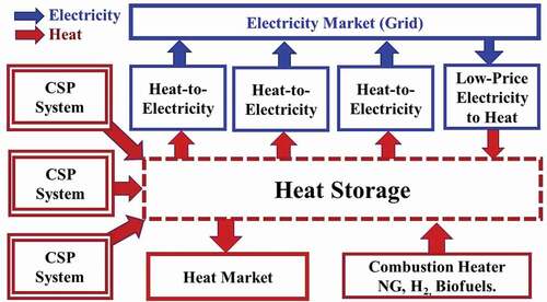
In the United States,Citation77 the average output of ground-based solar systems varies from 4.3 to 11.4 W/m2. To match the yearly energy output of a 1000-MW(electric) nuclear plant with a 100-GW.h heat storage system, the total CSP land area would be near 130 km2 (50 square miles) for the total output. There is considerable experience in pumping hot oil over distances of kilometers. Steam injectionCitation78 is used to heat underground heavy oil and tar sands to raise temperatures and convert the oil into a hot liquid that can then be pumped to the surface and then to storage facilities. The storage and power block economics of scale are greater than the additional costs of pumping hot fluid a few kilometers. The heat storage systems and power blocks become identical for nuclear, utility-scale CSP and fossil systems with CCS. Systems for pumping hot salts should be equally viable, but there is not the experience base.