
Abstract
The eBlock37 is a subscale electrically heated and heat-pipe-cooled prototype of a fast spectrum microreactor that is under development at Los Alamos National Laboratory. The prototype consists of an electrically heated core and gas-cooled heat exchanger. These subassemblies, both built from 316 L stainless steel, are thermally linked by an array of 37 sodium heat pipes that transfer a nominal 100 kW from the core at 700°C. An overarching objective of this effort is to overcome challenges associated with core block and heat exchanger manufacture and integration of high-temperature heat pipes into the assembly. Components that would be safety critical in an actual reactor, such as the heat pipe wicks, are being built under a Nuclear Quality Assurance 1 quality program. The completed assembly is intended for non-nuclear electrically heated testing, which will be conducted at a demonstration facility at Idaho National Laboratory. This paper provides a top-level summary of the efforts to date.
Keywords:
I. INTRODUCTION
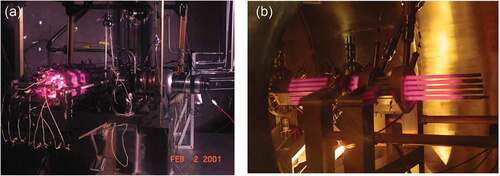
Heat pipes were first devised to provide ancillary electricity from nuclear rocket engine waste heat through thermionic energy conversion.Citation1 Since then, alkali metal heat pipes have been proposed as a primary means to extract fission heat from space nuclear reactors, allowing for electricity production by thermoelectric, Stirling, or Brayton energy conversion.Citation2–4 Alkali metal heat pipes that use potassium, sodium, or lithium working fluids have been developed and well characterized for these applications. In the 1980s, the Jet Propulsion Laboratory/Los Alamos National Laboratory (LANL) Space Power Advanced Reactor program resulted in a number of single heat pipe technology demonstrations at temperatures approaching 1500 K, but the 2.2-MW reactor design was never built.Citation2 In the early 2000s, two electrically powered heat pipe reactor demonstration units were built using LANL sodium heat pipe technology and were tested at the National Aeronautics and Space Administration’s (NASA’s) Marshall Space Flight Center (MSFC). shows both of these units operating near 700°C. shows the SAFE-30 unit, which was tested in 2001. The electrically heated core at the evaporator end of the heat pipe array was thermally linked to calorimeters and a free piston Stirling engine on the condenser end of the heat pipe array. shows the SAFE-100a unit with sodium heat pipe condensers connected to a Brayton cycle heat exchanger.Citation5 Both the SAFE-30 and the SAFE-100a designs consist of an array of discrete heat pipe modules, with each module having four or three fuel tubes, respectively, bonded to each individual heat pipe evaporator. Electrical cartridge heaters that fit into the fuel tubes simulated fission heat produced by nuclear fuel in the core. For the SAFE-30, standard commercial cartridge heaters were used, whereas custom cartridge heaters were fashioned for the SAFE-100a.
Fig. 1. The eBlock37 predecessors: (a) the LANL-built SAFE-30 demonstration tested at the NASA MSFC in February 2001 and (b) the LANL/MSFC-built SAFE-100a demonstration tested at the NASA MSFC in April 2004.
The focus of the current work builds on previous research by aiming to demonstrate the feasibility of heat pipe use in microreactor applications. The eBlock37 currently under development at LANL is a subscale fast spectrum microreactor prototype that uses an array of 37 heat pipes operating at 700°C to transfer a nominal 100 kW of thermal energy from the reactor core to an adjacent gas-cooled heat exchanger.
II. OBJECTIVES
This study focuses on two primary areas: the fabrication and functionality of a subscale microreactor prototype. Efforts to date have focused on demonstrating the feasibility of microreactor fabrication from design to final product. When fabrication is complete, work will then focus on demonstrating overall system and heat pipe performance by means of non-nuclear electrically heated testing with the goal of further understanding the power mechanism driving heat pipe microreactor designs.
To place the level of effort of this first-of-a-kind eBlock37 prototype in perspective, it is useful to compare it to existing and proposed production systems. compares rough level-of-effort estimates for the mass production of an automobile, the production of the eBlock37 microreactor prototype, and a possible mass-produced microreactor. Both a production automobile and the eBlock37 transfer about 100 kW to an ultimate heat sink, whereas a production microreactor would be capable of transferring more than 5 MW. A typical 100 000-unit-per-year production automobile with a 10-year design life is composed of approximately 30 000 distinct parts. A more limited generic microreactor production run of ~1000 units may contain half as many distinct parts. This generic reactor would have an approximately 5-year design life. The eBlock37 system has a 3-month design life, coinciding with the planned electrical demonstration duration, and part count exceeding 3000 after accounting for tooling. Development of a highly refined new model of automobile can take from 2 to 5 years for a team of up to 1000 personnel. It is anticipated that it will take a team of at least 100 personnel over 5 years to develop a generic microreactor prototype. Because of its much more modest objectives in terms of power, end use, and design life, the eBlock37 has taken a team of about ten engineers a little over 2 years to design and build.
TABLE I Level of Effort
III. REQUIREMENTS
The following sections outline the requirements pertaining to the eBlock37 test article, the test chamber, and documentation.
III.A. Test Article Requirements
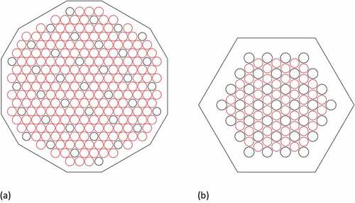
Scaling of reactor cores to achieve both full thermal-hydraulic and nuclear criticality similarity is seldom possible. shows cross sections of two subscale reactor core concepts that are both limited to 37 heat pipes (outlined in black). The remaining holes, outlined in red, hold nuclear fuel pin simulators. The configuration in is capable of reaching criticality, but its heat pipe hole pattern is not thermal hydraulically representative of a large-scale heat pipe reactor core. Although the eBlock37 configuration in could not achieve criticality regardless of fuel enrichment or reflector placement on the core boundary, the pattern of fuel pins and heat pipes is representative of a much larger configuration that could achieve criticality and meet thermal-hydraulic requirements.
Fig. 2. (a) Core configuration that would be capable of achieving criticality with low-enriched uranium and (b) the eBlock37 subcritical core cross section.
Upon review of the aforementioned core configurations, the eBlock37 subcritical core layout was selected to embody representative elements of a full core design within the scope of a low-budget fabrication demonstration. Stainless steel 316 L was chosen for construction of the eBlock37 because of its relatively low cost and its ability to maintain adequate mechanical properties at high operating temperatures. The eBlock37 is approximately 2 m in length, with the Core37 and eXchanger37 subassemblies each making up about half of the full test article length. Such length is needed to achieve a nominal operating temperature of 700°C and a nominal power output of 100 kW at the evaporator exit with the chosen sodium working fluid. All design choices have been made with a horizontal, simply supported configuration in mind. The analyses described in Sec. V were conducted to provide an initial design assessment and to inform future design iterations. Overall, eBlock37 design components, materials, and fabrication methods were chosen using the best available engineering practices. Mechanical codes and standards were abided by when possible.
III.B. Test Chamber Requirements
The test chamber and test stand were designed to accommodate the eBlock37 subcritical test article and all necessary instrumentation. Where possible, additional considerations were taken into account for other test article design contingencies in the event that future testing on a larger-scale configuration capable of reaching criticality became necessary or other design improvements were made.
Testing of the subcritical eBlock37 will be conducted for system characterization. Initial slow tests will be performed to evaluate elasticity of the structure with and without heat pipes. Thermal balance testing will be conducted to gauge system performance (e.g., temperature, strain) during system progression from startup to steady-state operation. Single heat pipe experiments will also be performed to obtain data on flow and temperatures. Heat exchanger cooling may be achieved using either an open-air loop or closed nitrogen loop, however, inert conditions are preferred to mitigate oxidation. If nitrogen is used as a coolant, successive dilution or a similar method will be used to obtain an oxygen level of no greater than 15 ppm. Safety protocols will be implemented to monitor facility oxygen levels. Pressure safety reviews will be implemented, and all applicable codes and standards will be followed.
To achieve necessary operating conditions, electrical service should be capable of supplying up to 250 kW from 208 volt alternating current three phase. Electrical power may be supplied to the core manually at constant power or with reactivity feedback simulation. Fluctuations in power should be avoided through the use of protective equipment such as an isolation transformer. Electrical safety reviews will be implemented and all applicable electrical codes and standards will be adhered to.
III.C. Documentation Requirements
Mechanical designs and electrical schematics are to be generated in computer-aided design software. Checked and approved drawings with appropriate geometric dimensioning and tolerancing will be generated for all test article and test chamber components. Where possible, material certifications will be obtained and saved as records.
IV. eBlock37 SYSTEM
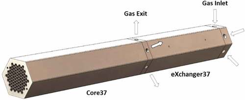
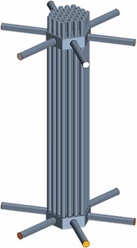
The eBlock37 system is composed of the eBlock37 and two gCart37 handling units. The eBlock37 consists of four primary subassemblies: Core37 subassembly, the eXchanger37 subassembly, the eWick37 array, and the Tube37 array. depicts the Core37 subassembly attached to the eXchanger37 subassembly. On the left end of the Core37 subassembly is the pattern of heat pipe and fuel pin holes shown in . The heat pipe holes and blind fuel holes extend the full length of the Core37 subassembly. The Tube37 array attaches to the heat pipe holes at the heat exchanger interface and the eWick 37 array extends through the length of both the heat pipe holes and the tubes. The Tube37 array, which functions as the condenser section for the heat pipes, is inserted in channels in the eXchanger37 subassembly.
Fig. 3. eBlock37 subcritical core assembly showing (left) the Core37 subassembly and (right) the eXchanger37 subassembly.
IV.A. Core37 Subassembly
The Core37 subassembly shown in is approximately 1 m long and contains a total of 91 holes: 37 of these holes house sodium heat pipe evaporators and 54 holes are for electrical cartridge heater installation. The web thickness between each of the holes is approximately 1.5 mm. A variety of fabrication techniques were considered to form the subassembly, including conventional machining and additive manufacturing of various length segments. Segment joining by hot isostatic pressing (HIP), vacuum hot pressing, laser bonding, and diffusion bonding was tested. Although electron-beam welding was met with poor results, both the HIP and diffusion bonding trials proved successful. Additional diffusion bonding trials are currently being performed on a subscale core block. Findings will aid refinement of the diffusion bonding processes for full-scale Core37 implementation.
Closures (not shown) welded to the end of the Core37 subassembly seal the heat pipes while allowing the electrical cartridge heaters to be inserted into the adjacent fuel pin holes. The electrical cartridge heaters are simple resistive elements that can have cosine-shaped axial power distribution to simulate the effects of geometric and material flux buckling in the axial direction. Radial effects can be simulated by multizone heater control from a central region to the edge of the core. Fast-spectrum heat pipe nuclear reactor cores possess negative reactivity feedback as expansion of the metallic core with increasing temperature induces fuel separation. Bragg-Sitton et al. developed a method to simulate neutronic feedback for the dynamic response of the SAFE-100a electrically heated core prototype using a virtual point kinetics model of the core embedded in the heater power control software.Citation5,Citation6 Power feedback was obtained by measuring the change in distance with a remote camera focused on a linear scale scribed atop the core block. Instead of the linear scale used for the SAFE-100a, a more advanced digital image correlation (DIC) system will be used to characterize expansion of the outer eBlock37 core block in the axial and radial directions. This DIC system will be coupled to a long-wavelength infrared system to provide both local temperatures and displacements of the core block.
IV.B. eXchanger37 Subassembly
The heat-pipe-to-heat-exchanger interface is common to all heat pipe microreactors under examination as of this writing. Although heat pipe reactors have been designed for other energy conversion techniques, such as thermionic, thermoelectric, Stirling, closed Brayton, and supercritical carbon dioxide cycles, for this application, a simulated open-cycle Brayton unit provides the right combination of scalability and operating pressure.
The eXchanger37 subassembly design pressure of 2 MPa accommodates typical open Brayton cycle units. However, to avoid pressure containment concerns during initial testing, the eXchanger37 will be operated with gas (e.g., air, nitrogen) circulating at under 103.4 kPag (15 psig). During operation, gas is circulated over the heat pipe surfaces through a series of three zones as shown in .
Fig. 4. eBlock37 cross-sectional layout.
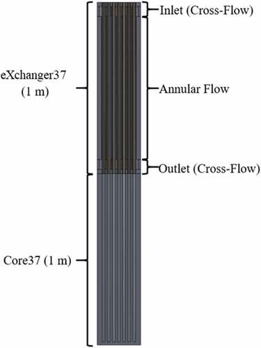
Cold gas enters the eXchanger37 subassembly inlet and flows across the Tube37 array. Warm gas is then diverted axially along an array of annular channels formed between the Tube37 array and through holes in the eXchanger37 body. Hot gas exits the annular channels and again transitions to cross flow at the eXchanger37 exit. The current eXchanger37 design uses heat pipes with smooth surfaces that are capable of providing adequate heat transfer rates for the low-pressure eBlock37 test article. Though not necessary for eBlock37 operation, ribbed surfaces have been shown to enhance heat transfer and may be applied to more advanced designs that require additional heat transfer.Citation7
IV.C. eWick37 Array
Heat pipes serve in a range of applications such as electronics, spacecraft, and nuclear power conversion. This results from their flexibility in terms of size, heat transfer capability, and angle of operation. Fluid return to the hot zone through a high-performance wick drives this versatility. A comparison between thermosiphons and heat pipes demonstrates the utility and adaptability. Thermosiphons rely solely on gravity to operate and must be inclined during operation, with the heated region being at the lowest point. Alternatively, heat pipes rely on the capillary action created by the wick to drive fluid circulation and can therefore operate at any angle within the corresponding wicking height, including in microgravity.
The shape of the heat pipe wick imposes order on a saturated liquid by (1) forming menisci between the condensate and the vapor and (2) allowing condensate to flow toward the heated zone. In the heated zone of a heat pipe, evaporation of the liquid produces vapor and increases pressure on the concave side of the wick’s meniscus. This pressure rise drives vapor toward the cooled zone and returns condensate to the heated zone through the wick. For a heat pipe to work correctly, the maximum capillary pressure rise, which is governed by largest pore in the heated zone, must be greater than the pressure drops in the liquid and vapor regions: ∆pmax ≥ ∆pl + ∆pv. The pressure drop in heat pipe wicks, ∆pl, is linear with local mass flow rate. The effects of stable vaporization in the heated region combine with unstable condensation of vapor in the cooled region. Viscous and turbulent inertial effects with possible pressure recovery may contribute locally to the vapor zone pressure change, ∆pv. The simplest heat pipe wicks are homogeneous, with a uniform pore structure that requires condensate to flow axially through the same pore structure that forms the surface menisci. depicts a cross section of a homogeneous wick. A homogeneous wick that produces high capillary pressure rise typically also has high resistance to condensate flow, which limits the axial heat transfer rate. Compound wicks address these performance limitations. Two compound wick geometries are especially attractive for high power density liquid metal heat pipes: a concentric annular gap wick () and an artery wick ().
Fig. 5. (a) Homogeneous, (b) concentric annular gap, and (c) artery wick geometries.
The concentric annular gap wick design was ultimately chosen for the eWick37 array because of its relatively simple fabrication process. The concentric annular gap wick allows condensate to freely flow toward the hot zone in a gap between the pipe’s inner surface and the outer surface of the porous material on which menisci form. To maintain capillary continuity, a solid plug seals the wick on the end nearest the heated zone. As a heat pipe warms, its working fluid expands. When the heat pipe is isothermal, excess condensate (typically 5% of charge) seals the condenser end of the wick to ensure capillary continuity. Because the wicks are a safety-significant component for reactor operations, the annular gap wicks manufactured for the eBlock37 are made to Nuclear Quality Assurance 1 quality standards.
IV.D. gCart37 Handling Unit
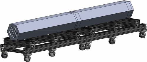
The gCart37 was developed to address handling challenges associated with the 700-kg eBlock37 by facilitating movement of the individual Core37 and eXchanger37 subassemblies during assembly activities and the eBlock37 as a whole. shows the Core37 and eXchanger37 subassemblies resting on the two articulated gCart37 handling unit segments. The Core37 subassembly rests on the leftmost segment and the eXchanger37 subassembly rests on the rightmost segment, allowing for independent movement of the two subassemblies. Casters enable freedom of motion, and a low center of gravity mitigates tipping. Locking the gCart37 casters permits safe lifting of the eBlock37 by an overhead or gantry crane via swivel hoist rings. Additionally, gCart37 support spacing allows for the eBlock37 to be moved by forklift. The gCart37 is used to stage all major fabrication operations, including welding of the heat pipe closures on the end of the Core37 subassembly, attachment of the Core37 to eXchanger37 subassemblies, and mounting of the eBlock37 assembly to the eFill.
Fig. 6. eBlock37 subcritical core mounted on gCart37 handling unit.
IV.E. eFill Sodium Charge Unit
The eFill is a scalable heat pipe charging and sealing apparatus that was developed with the intent of easing and automating the manufacture of heat-pipe-cooled microreactors. Desired attributes for this system included rapid, reliable, and inexpensive filling of an ~103 heat pipe monolith in several days or less.
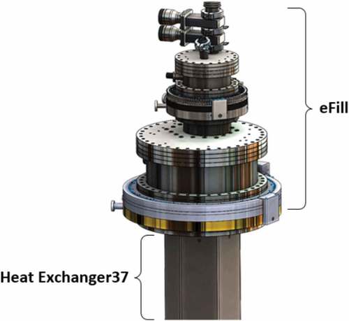
The eFill interfaces directly with the eBlock37 and uses multiple configurations for completing distinct steps of the manufacturing process. One configuration enables charging each heat pipe in the array with high-purity sodium working fluid to each heat pipe in the array, whereas a separate configuration facilitates sealing of the heat pipes. All eFill processes are conducted under inert gas or vacuum conditions to prevent contamination of the sodium. shows a rendering of the eFill sodium charge unit mounted via a flange atop the eXchanger37 subassembly.
Fig. 7. eFill sodium charge unit atop the eXchanger37 subassembly.
The fill system methods used represent a significant departure from earlier approaches for alkali metal fill. Simple and flexible filling steps are intended to allow normally skilled operators to perform the tasks easily. The design progression centered on successive simplification. Implementation of a failure modes and effects analysis and Bayesian belief network guided process development by identifying least reliable process steps. This permitted selection of a design that allows for appropriate levels of product inspection and quality control.
V. PERFORMANCE PREDICTIONS
This section details the analysis work conducted to assess the thermal and structural system performance of the eBlock37.
V.A. Thermal Capacity of Sodium Heat Pipes
Performance capability of the eBlock37 is dependent on both the ability of the heat pipe array to transmit thermal output from the Core37 subassembly to the eXchanger37 subassembly and the ability of the eXchanger37 to remove the transmitted thermal power from the heat pipe array.
The stainless steel sodium heat pipe array was designed to transfer a combined 100 kW of thermal power at an operating temperature of 700°C. Thermal capacity of the heat pipe array was calculated using the HTPIPE analysis package based on the design parameters presented in (CitationRef. 8).
TABLE II Heat Pipe Parameters
The capability of the eXchanger37 was calculated as a sum of thermal power that was leaving the two cross-flow sections and the annular channel for each of the 37 heat pipes in the array. The total thermal power of the system was calculated for input mass flow rates of 0.25, 0.20, 0.15, 0.10, and 0.05 kg/s with an air inlet temperature of 350°C.
Comparing the thermal capacity of the heat pipe array to the capability of the heat exchanger provides a predicted performance of the system. plots the performance of the system as a function of the inlet mass flow rate, mdot,i.
Fig. 8. Heat pipe array capacity compared to eXchanger37 capacity.
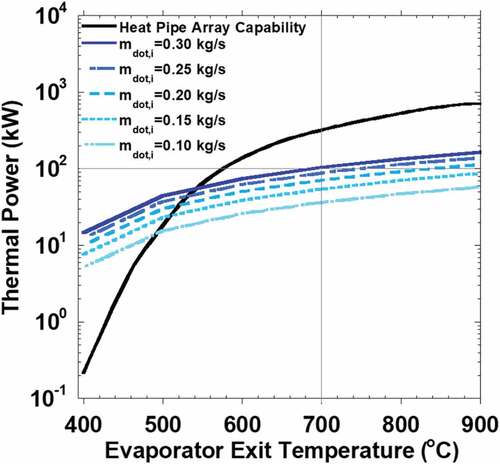
Performance findings show that the eBlock37 is limited by the minimum power capability, meaning that the system is limited by the capacity of the heat pipe array at temperatures less than 475°C and is limited by the capacity of the heat exchanger at temperatures greater than 550°C. shows that the heat pipe array is capable of transferring 100 kW(thermal) at 700°C with appropriate eXchanger37 flow parameters.
V.B. Steady-State Thermal Analysis
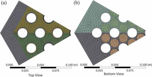
Thermal analysis was conducted on the eBlock37 in ANSYS to evaluate the expected temperature distribution and thermally induced stresses under steady-state operation. Temperature-dependent bilinear elastic-plastic material properties were used to represent the 316 L stainless steel eBlock37. Preliminary analyses were conducted to obtain further insight into where the largest stress concentrations were expected to occur, and meshing was refined in regions deemed to be of concern. Fillets were incorporated at vertices within the heat exchanger to reduce incurred stresses in regions where initial assessments showed large temperature gradients and thermally induced stresses. Top and bottom views of the meshed assembly are shown in , and an overview of the analysis model parameters is provided in .
TABLE III eBlock37 Model Parameters
Fig. 9. (a) Top and (b) bottom views of meshed ANSYS model.
Thermal boundary conditions within the eXchanger37 were determined by evaluating fluid temperature and heat transfer coefficients (HTCs) for each of the heat exchanger regions [i.e., inlet (cross flow), annular flow, and exit (cross flow)]. Cross flow occurring in the eXchanger37 inlet and exit was assumed to have a uniform fluid temperature and HTC on the heat pipe walls. Values for these parameters are shown in .
TABLE IV Cross-Flow Zone Thermal Boundary Conditions
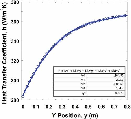
Fluid temperatures and HTCs in the annular region are based on parallel flow heat exchanger relations such that each is a function of position along the length of the channel. The plots shown in show fluid temperature and HTC based on location, with the starting position (y = 0 m) being at the entrance of the annular channel, farthest from the reactor interface.
Fig. 10. Fluid temperature as a function of channel position.
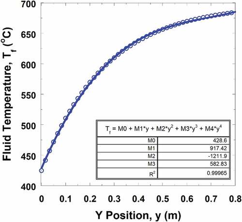
Fig. 11. HTC as a function of channel position.
Several assumptions were made to allow for solution of the thermal model. First, internal heat pipe temperatures were defined as isothermal with a constant temperature of 700°C. All external surfaces of the eBlock37 were considered perfectly insulated. Additionally, each fuel rod was assumed to have a heat flux of 22.5 kW/m2, which was determined by energy balance.
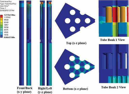
Temperature and heat flux contours determined using the aforementioned thermal boundary conditions are shown in respectively.
Fig. 12. Heat exchanger and reactor assembly steady-state temperature distribution.
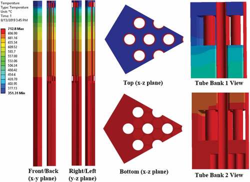
Fig. 13. Heat exchanger and reactor assembly steady-state heat flux distribution.
V.C. Structural Analysis
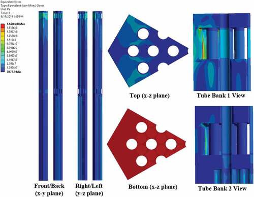
Upon completion of the previously described thermal analysis, structural boundary conditions were applied to the eBlock37 as a means of evaluating the stresses incurred by the combination of thermal loading and an internal fluid pressure loading of 2 MPa. The structure was fixed in the x-z plane at the base of the Core37 subassembly, allowing for deflection only in the y-direction (i.e., parallel to the heat pipe axes). Additionally, a cylindrical support was applied to the inner surface of the centermost heat pipe to prevent rotation of the assembly. Results for deformation and stress can be found in , respectively.
Fig. 14. Heat exchanger and reactor assembly steady-state deformation.
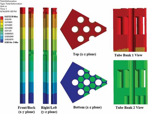
Fig. 15. Heat exchanger and reactor assembly steady-state stress distribution.
V.D. Computational Fluid Dynamics Analysis
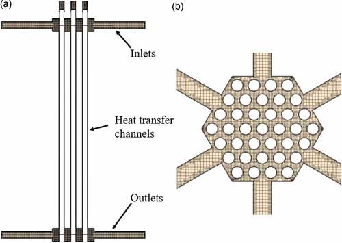
Computational fluid dynamics (CFD) analyses were conducted in Starccm+, Version 15.06.007-R8, to provide a higher-fidelity assessment of flow distribution and heat transfer within the eXchanger37. Initial design iterations contained only three inlet and three outlet ports. After some consideration, additional ports were added to enable a more uniform flow distribution and corresponding heat transfer. shows the model used for CFD analysis, which includes six inlet and six outlet ports.
Fig. 16. eXchanger37 CFD fluid model.
Consistent with the previous analysis, inlet air temperature was assumed to be 350°C, heat pipe surface temperatures were assumed to be 700°C, and all other surfaces were considered adiabatic. Isobaric (0.1 MPag or 15 psig), temperature-dependent air properties were defined, with relationships based on National Institute of Standards and Technology data.Citation9
A grid sensitivity study was performed with four different meshes (M1 = 2 million cells, M2 = 6 million cells, M3 = 13 million cells, and M4 = 25 million cells) to quantify the optimal mesh specification for the current application. Mesh statistics for each case are shown . The outlet coolant temperature and pressure drop were evaluated along with different mesh sizes, showing an asymptotic behavior beyond mesh M3. Mesh M3 was therefore deemed the optimal mesh for analysis of the eXchanger37. Hereafter, all results presented in this paper are based on the optimal mesh defined from the grid sensitivity study.
TABLE V Mesh Statistics for Grid Sensitivity Study
A hexagonal mesh was chosen as a base mesh with seven layers of the prism mesh along the heat transfer surface to resolve the viscous boundary layer in the flow channel and help produce a well-converged energy equation in the stimulation. After several turbulence model tests, Menter’s k-ω Shear Stress Transport turbulence model was employed in the simulation.
A series of iterative simulations was conducted using the meshed model shown in to evaluate inlet flow conditions needed to achieve the desired 100-kW cooling capacity. This was accomplished by incrementally increasing the inlet air flow rate until the target thermal energy dissipation was achieved. Results showed that a total air mass flow rate of 0.33 kg/s was required.
Fig. 17. (a) Cross-sectional view and (b) top view of meshed CFD model.
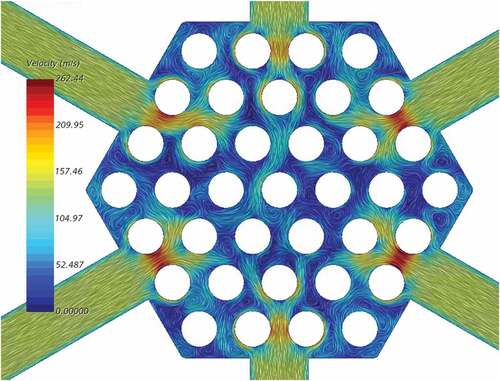
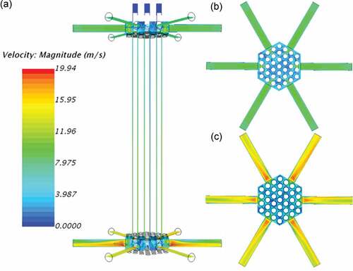
Velocity profiles through the eXchanger37 are displayed in . No critical stagnation or recirculation was observed in either the inlet or outlet cross-flow regions. However, it was noted that air velocities at the outlet were nearing trans–sonic velocity, which implies that other cooling mediums may need to be considered to meet the desired thermal target.
Fig. 18. A flow visualization of the air flow mixing distribution in the upper plenum.
As intended, stagnation was observed in the heat exchanger cap as a result of narrow channels preventing upward flow. The heat exchanger cap was designed with narrow openings to accommodate heat pipe thermal expansion. Openings were made as narrow as possible to ensure that the path of least resistance for fluid flow was through the heat exchanger. shows that the heat exchanger cap design is effective in mitigating unnecessary thermal capacity losses at the heat exchanger inlet.
Stagnation of air in the cap creates an increase in fluid temperature as shown in . This potentially reduces the severity of temperature gradients and corresponding thermal stresses observed at the heat exchanger inlet in the previous analysis.
also shows the expected gradual increase in air temperature between the entrance and exit of the annular flow region. Though relatively minor, some variation in air temperature profiles can be seen in heat pipes located on the perimeter of the eXchanger37. The most notable difference occurs in annular channels located at vertices of the heat exchanger, which appear to increase in temperature farther down the length of the channel than those adjacent as shown in .
shows the air temperature and velocity profiles at the center of the annular flow region. The flow distribution feeding into each of the 37 annular channels is nonuniform because of the abrupt transition and structural obstacles in the inlet cross-flow region as shown in . Channels with higher air velocities experience higher heat transfer rates and exhibit a correspondingly greater temperature drop as demonstrated in .
Local HTCs were evaluated in the baseline air flow condition and are illustrated in . High HTC values were observed upstream in the annular channel because of the large temperature gradient between the flowing air and heat pipe surface. HTC values became saturated in the middle of the annular flow channel and transitioned to a constant value in the downstream side.
It is worth noting that heat transfer performance over the 37 channels is not uniform and that flow distribution in the current design dictates the initial heat transfer performance of individual channels. This can be seen to be particularly true at the transition from the inlet cross-flow region to the annular flow channel by comparing the air velocity distribution in the inlet cross-flow region () to HTCs at the entrance of the annular flow region (). Channels located directly in front of the air inlet, where velocities are largest, exhibit the highest HTCs.
An overall assessment of individual heat pipe performance is shown in . Reiterating previously discussed findings, analysis results showed that annular channels closest to the center (i.e., HP12, 13, 20, 26, 25, 18, 19) and those at the vertices of the eXchanger37 (i.e., HP01, 04, 22, 37, 34, 16) exhibited lower than average power dissipation. These heat pipes are denoted by the red dotted lines in . Thermal energy dissipation ranged from just under 2 kW at the center of the heat exchanger (i.e., HP19) to approximately 3.25 kW for heat pipes directly in front of the heat exchanger inlet ports.
To demonstrate the capacity of the eXchanger37 with desirable target thermal energy while alleviating engineering concerns regarding air flow approaching supersonic velocity and potential oxidation, the aforementioned CFD analysis was also conducted using helium as a cooling fluid. Again, iterative analyses were performed to identify the helium flow rate necessary to achieve the desired 100-kW thermal energy dissipation. Results showed that a total helium mass flow rate of 0.06 kg/s was capable of achieving the same cooling capacity as a total air mass flow of 0.33 kg/s. shows that although magnitudes differ, the overall flow distribution was found to be similar to that shown in for air. Additionally, the distribution of thermal energy dissipation was found to be comparable to that shown in . Although the capacity of the eXchanger37 with both cooling fluids was found to be satisfactory for the current application, improvements to the channel flow design may be implemented to further reduce thermal-mechanical stress and lifecycle limitations.
Fig. 19. (a) Side view and (b) bottom view in the lower plenum of air velocity profiles.
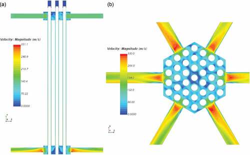
Fig. 20. Heat exchanger cap stagnation for air working fluid.
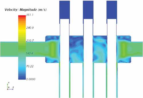
Fig. 21. (a) Cross-sectional view and (b) side view of air temperature profiles.
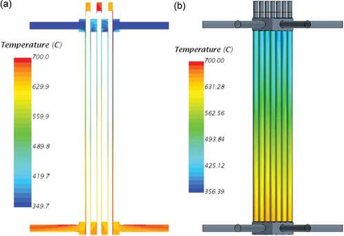
Fig. 22. (a) Midplane air temperature and (b) velocity profiles.
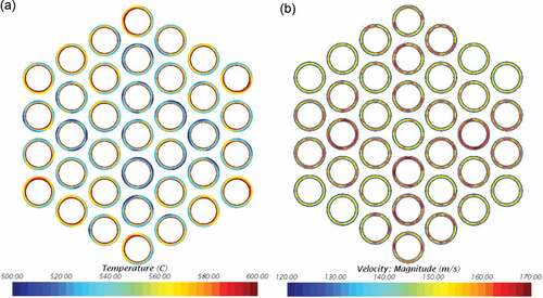
Fig. 23. Side view of annular channel air HTC profiles.
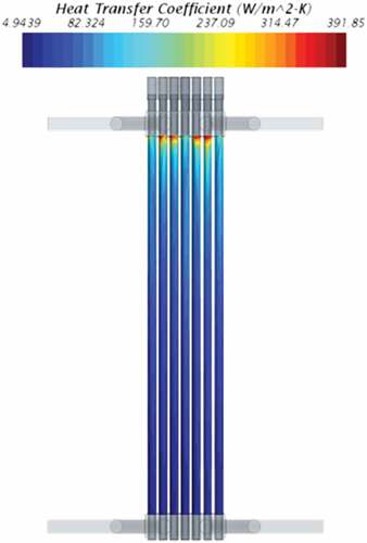
Fig. 24. Heat pipe power dissipation by location for air working fluid.
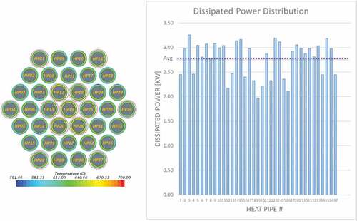
Fig. 25. (a) Supercritical helium velocity profiles in the overall heat exchanger, (b) inlet cross-flow region, and (c) outlet cross-flow region.
V.E. Additional Analyses and Design Improvements
Follow-up analyses were conducted to estimate system service life and heat exchanger flow distribution. ANSYS was used to conduct analyses per the rules of the American Society of Mechanical Engineers Boiler & Pressure Vessel Code Section III, Division 5, Subsection HB, Subpart B, to further evaluate the effect of high-temperature operation and corresponding temperature gradients on the eBlock37’s service life.Citation10 Of all assessments conducted, creep-fatigue damage was found to be the most life-limiting. The system life was estimated to be just three cycles (20-h ramp up, 700-h high-temperature operation, and 20-h rampdown), with the hot section of the heat exchanger being the most limiting. Overall findings show that the eBlock37 design, as presented here, would not be suitable for long-term service.
Using findings from all of the previously discussed analyses, additional design improvements were made to reduce observed stresses and increase the corresponding service life to further mitigate any concerns of failure. Fillet radii on heat exchanger cross-flow-region vertices were increased to lessen cycle-limiting stresses in the hot and cold regions of the eXchanger37 subassembly. Additionally, the interface between the Core37 subassembly and eXchanger37 subassembly was revised to decrease the observed temperature gradients.
VI. CONCLUSION
The eBlock37 is a subscale electrically heated and heat-pipe-cooled prototype of a fast spectrum microreactor under development at LANL. As of the writing of this paper, the eBlock37 design is complete and fabrication of components such as the eWick37, eXchanger37 subassembly, and Core37 subassembly is nearing completion at various vendors. Arrangements are being made to charge the heat pipe array using the eFill system. When this is complete, the eBlock37 assembly will be shipped to the Microreactor Agile Non-Nuclear Experimental Testbed at Idaho National Laboratory, where it will be instrumented and will undergo system performance testing.Citation11 Testing will be conducted to characterize individual heat pipes and the overall eBlock37 structural and thermal behavior during startup and steady-state operations.
Acknowledgments
This work was supported by the U.S. Department of Energy, Office of Nuclear Energy under the Advanced Reactor Technology portfolio’s Microreactor Program. The content represents ongoing efforts by the Microreactor Program to enable accelerated development and demonstration of microreactor technology. Although uninvolved with the eBlock37 or eFill development efforts, Morgan Biel, Nick Diskerud, Kyle Hammond, and Briana Lucero made many contributions to the earlier eFill7 concept.
Disclosure Statement
No potential conflict of interest was reported by the authors.
References
- G. M. GROVER, T. P. COTTER, and G. F. ERICKSON, “Structures of Very High Thermal Conductance,” J. Appl. Phys., 35, 1990 (1964); https://doi.org/10.1063/1.1713792.
- R. G. PALMER et al., “Nuclear Reactor System Study for NASA/JPL Final Report,” LA-9498-MS, Los Alamos National Laboratory (1982).
- R. S. REID, J. T. SENA, and A. L. MARTINEZ, “Sodium Heat Pipe Module Test for the SAFE-30 Reactor Prototype,” AIP Conference Proceedings, 552, 869 (2001); https://doi.org/10.1063/1.1358021.
- D. I. POSTON, R. J. KAPERNICK, and R. M. GUFFEE, “Design and Analysis of the SAFE-400 Space Fission Reactor,” AIP Conference Proceedings, 608, 578 (2002); https://doi.org/10.1063/1.1449775.
- S. M. BRAGG-SITTON, “Heat Pipe Reactor Dynamic Response Tests: SAFE-100a Reactor Core Prototype,” Proc. of the Space Nuclear Conference 2005, San Diego, California, June 5–9, 2005 (2005).
- S. M. BRAGG-SITTON, T. J. GODFROY, and K. WEBSTER, “Improving the Fidelity of Electrically Heated Nuclear Systems Testing Using Simulated Neutronic Feedback,” Nucl. Eng. Des., 240, 10, 2745 (2010); https://doi.org/10.1016/j.nucengdes.2010.04.036.
- K. TAKASE, “Forced Convective Heat Transfer in Square-Ribbed Coolant Channels with Helium Gas for Fusion Power Reactors,” Fusion Eng. Des., 49, 349 (2000); https://doi.org/10.1016/S0920-3796(00)00395-1.
- K. A. WOLOSHUN, M. A. MERRIGAN, and E. D. BEST, “HTPIPE: A Steady-State Heat Pipe Analysis Program, A User’s Manual,” LA-11324-M, Los Alamos National Laboratory (1988).
- P. J. LINSTROM and W. G. MALLARD, Eds., “NIST Chemistry WebBook, NIST Standard Reference Database Number 69,”National Institute of Standards and Technology; https://webbook.nist.gov/chemistry/ (accessed Mar. 2, 2021).
- G. YE, M. C. MESSNER, and T. L. SHAM, “Example Evaluation of a Representative Heat Pipe Test Article Design for Structural Acceptability Using ASME Design Rules,” ANL-ART-200 161982, Argonne National Laboratory (2020); https://doi.org/10.2172/1658587.
- D. P. GUILLEN et al., “Development of a Non-Nuclear Microreactor Test Bed,” Trans. Am. Nucl. Soc., 121, 1623 (2019); https://doi.org/10.13182/T30925.