
 ?Mathematical formulae have been encoded as MathML and are displayed in this HTML version using MathJax in order to improve their display. Uncheck the box to turn MathJax off. This feature requires Javascript. Click on a formula to zoom.
Abstract
High-temperature microreactors can play a role in developing reliable, portable energy sources for off-grid remote locations, microgrid concepts, and industrial process heat. Portability and passive safety criteria tend to skew microreactor structural component designs toward complex geometries, high thermal stresses, and design bases with large numbers of startup/shutdown cycles. Current design rules, as typified by Section III of the American Society of Mechanical Engineers (ASME) Boiler & Pressure Vessel Code, are less than optimal for these conditions, particularly for preliminary component designs where developers need to rapidly consider a large number of potential component configurations. This paper presents a design method targeted toward rapid, efficient evaluation of preliminary component designs using modern finite element analysis. The new method retains key connections with the ASME Code rules and design data while streamlining the design approach. This paper presents the design method, several verification examples illustrating the similarities and differences between the new method and the current ASME rules, and the application of the new approach to the evaluation of a test article mimicking key features of a heat pipe–cooled microreactor.
I. INTRODUCTION
Microreactor designs with thermal outputs of less than 20 MW are drawing increasing attention for microgrid,Citation1 off-grid, process heat,Citation2 and portable generator applications. Many of the concept designs operate at higher temperatures than the current light water reactor fleet. This requires suitable high-temperature design methods for the safe, effective design of structural components.
Stress relaxation complicates high-temperature design. Even for constant mechanical and thermal loading, the stress distribution in a component operating in the creep regime changes over time. For a component under steady load, understanding the difference between the initial stress distribution and the final, relaxed stress distribution can be critical to accurately design components with large thermal stresses. The high-temperature design community uses the conceptual model of stress classification to consider these different types of stresses—those that remain in the steady stress distribution, even in the limit of providing infinite time for creep stress relaxation, and those that relax to zero gradually over time. The constant stress that does not relax over time is the primary stress, while stresses that relax over time are secondary or peak stresses.Footnotea A classic example of a primary stress is the stress caused by internal pressure in a simple cylindrical vessel. The classic example of a secondary stress is the self-equilibrating stress cause by a linear, through-wall thermal gradient.
Section III, Division 5, of the American Society of Mechanical Engineers (ASME) Boiler & Pressure Vessel Code rules for the design and construction of high-temperature nuclear reactorsCitation3 typifies current high-temperature nuclear structural design approaches. These rules were developed based on extensive design experience from the Clinch River Breeder Reactor ProgramCitation4 (CRBRP) and prior work on the EBR-II and other high-temperature concept reactors. These rules could be applied to produce adequate, safe microreactor component designs. However, several aspects of the current ASME rules are less than optimal for the design of microreactors, particularly in the preliminary design stage where designers are evaluating many different design concepts. In particular, the Section III, Division 5, primary load criteria rely on stress linearization and classification procedures,Citation5 necessary before the development of modern finite element analysis (FEA) to account for stress redistribution due to creep and plasticity. Designers have ample experience correctly applying stress classification to standard structures like vessels, nozzles, and piping system components, and the ASME Code provides guidance for stress classification for a wide variety of typical components. However, microreactor geometries were not considered in developing the stress classification guidance and designer experience does not cover some of the complex components envisioned for future microreactors, meaning accurate stress classification will be extremely challenging for microreactor designs. The need for stress classification and other requirements make the current ASME rules difficult to automate using modern FEA software.
This difficulty in automating the rules is especially challenging during preliminary design. For preliminary design, designers require a rapid assessment of the feasibility of many different concept designs. However, the ASME primary load design rules, which were historically often used as a fast, preliminary design method, do not account for secondary thermal stresses or fully account for the effect of stress concentrations due to component discontinuities. Both effects had less significance for large, sodium-cooled fast reactor concepts but are likely to control the design of low-pressure microreactors. The current ASME rules do adequately account for thermal and peak stresses, but only as part of the detailed cyclic load criteria that, historically, have not been used for preliminary design.
As such, microreactor developers will need fast, reliable methods for preliminary component design that account for thermal and peak stress, and that can be automated in modern FEA software. This paper describes the development of a design method that meets these criteria, including a description of the step-by-step design process. In addition, this paper describes several example problems aimed at demonstrating the similarities and differences between the new approach and the current ASME rules, as well as a description of the application of the new method to a test article representative of a heat pipe–cooled microreactor.
Section II describes the design procedure and outlines the decisions made in constructing the new method. Section III describes several verification examples aimed at demonstrating the similarities and differences between the current ASME and new design methods. Section IV applies the new design approach to evaluate a heat pipe test article emulating a heat pipe–cooled microreactor, and Sec. V summarizes the paper and describes potential future work on design methods for microreactor components.
II. NEW HIGH-TEMPERATURE DESIGN METHOD
II.A. Current ASME High-Temperature Nuclear Design Practice
The current rules in the 2019 edition of Section III, Division 5, of the ASME Boiler & Pressure Vessel Code require a component to pass four design checksCitation3:
primary load design, comparing the primary stress intensity to two different allowable stress values
accumulated strain limits, accounting for ratcheting and creep deformation
creep-fatigue criteria, aimed at guarding against the initiation of creep-fatigue damage
buckling checks for both time-independent and time-dependent buckling.
The ASME Code provides two design methods for the strain accumulation and creep-fatigue criteria: design by elastic analysis and design by inelastic analysis. As the names suggest, the elastic rules start with a linear elastic stress analysis of the component and the inelastic rules start with a full inelastic analysis, accounting for both creep and time-independent plasticity. The design by elastic analysis rules is conservative and is based on bounding methods. The design by inelastic analysis rules is less conservative and is closer to an exact analysis of the component. The current primary load design rules are based on an elastic analysis, and the buckling rules require an inelastic analysis to evaluate creep buckling, unless the component meets time-dependent buckling exemption criteria.
Historically, designers applied the design by elastic analysis rules to develop preliminary designs and followed up with an inelastic analysis, especially for complicated or difficult components.Citation4 For historical reactor designs, especially the sodium-cooled fast reactor design in the CRBRP, designers used the design by elastic analysis primary load design rules to develop a rough preliminary design. These rules are simple to apply, at least compared to the strain accumulation, creep-fatigue, and buckling criteria, and at least for some types of components, they only require a simple stress analysis to determine the appropriate primary load stress intensity. Moreover, current ASME nonnuclear high-temperature design methods are similar to the Section III, Division 5, primary load design criteria, meaning this approach has become common practice in the high-temperature design community.
II.B. Preliminary Design for Microreactors
The current ASME primary load design rules will not produce reasonable initial designs for many types of microreactor components, especially compact, integrated designs. These components differ from conventional, full-sized, high-temperature reactor components in several ways that complicate the application of the current ASME primary load design criteria:
Microreactor components often have complicated geometries with corresponding complex states of stress. The ASME elastic analysis rules work best for standard, biaxially stressed pressure vessel structures. In particular, executing an ASME stress classification can be very challenging for complex components.
Microreactor components often retain very low pressures. This is similar to other high-temperature reactor designs, including the full-scale CRBRP design. However, microreactors are often designed to experience many more load cycles than a full-scale reactor. For example, concept microreactors are often portableCitation6 or designed to run in a load following mode.Citation7 Under these conditions, design methods that neglect the secondary thermal stresses will produce poor preliminary designs that are likely inadequate when considering the strain accumulation and creep-fatigue design criteria.
Similarly, microreactor components can have severe geometric constraints dictated, for example, by the need for reactor portability. These constraints tend to increase the design complexity and the number of design iterations required to produce an effective preliminary design. A preliminary design approach taking advantage of modern FEA and computer postprocessing could speed up this process.
In addition, the current ASME primary load design rules suffer from additional limitations common to all high-temperature reactor types:
The stress classification and linearization procedure is difficult to execute and to automate in modern FEA software.
The design by elastic analysis approach only conservatively accounts for a limited amount of load redistribution in a component caused by inelasticity. The current design approaches underestimate the redistribution capacity of components and so tend to underestimate permissible design lives.
These shortcomings in the current ASME primary design rules demonstrate the need for a preliminary design method more compatible with the loading and geometries expected for future microreactor components.
II.C. Proposed Design Method
To address the limitations of the current ASME primary load design approach, we developed a new preliminary design method that has been proposed for incorporation into the ASME Boiler & Pressure Vessel Code as a Nuclear Code Case. The new approach can be viewed as a companion to two current Code Cases, N-861 and N-862, providing design rules for the strain accumulation and creep-fatigue criteria based on an elastic perfectly plastic (EPP) stress analysis.Citation8,Citation9 Like those two current Code Cases, the new design rule attempts to simplify the ASME design process by eliminating stress classification and linearization and generally providing rules more compatible with modern FEAs.
An Argonne National Laboratory (ANL) technical reportCitation10 provides the full, detailed design rules for the new design approach along with extensive technical background. The focus of the current paper is on applying the approach to develop preliminary designs for microreactor structural components. As such, the following presents a simplified version of the full proposed Code Case rules. The simplified version does not include many of the details in the complete rules, specifically eliminating the following:
ASME design loading case and associated allowable stress
service load categorization in service level A, B, C, and D loads. These load cases have to do with the severity and expected frequency of the loading (which in turn alters the definition of the allowable stress used in design). The simplified rules here consider only service level A
time fraction approach for combining the effects of multiple service load cases. The simplified approach only considers a single, representative load history
detailed instructions on executing the EPP limit load and simplified inelastic analyses
alternative, simplified approach for the global service analysis for isothermal structures.
The simplified version of the design approach requires two separate design checks. is a flowchart summarizing the process.
Fig. 1. Flowchart illustrating the simplified design process.
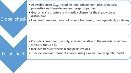
II.C.1. Global Service Check
This check compares the fully redistributed, steady-state stresses in the component against the ASME primary load allowable stress . It is analogous to the current ASME design by elastic analysis primary load design service load criteria and uses the same allowable stress. The Code defines the allowable
in terms of extrapolated time-dependent properties, and so the values of the allowable stress depend on temperature and the component design life
.
This check uses a limit load analysis to assess whether the combination of the structure and relevant allowable stress is acceptable. To do this, the method converts the ASME allowable stress into a pseudoyield stress for use in the limit load analysis. If the component can withstand the loading when analyzed as EPP with the allowable stress-based pseudoyield stress, then it passes the design check. The limit load analysis can be implemented numerically using a finite element stress analysis. To do this, the designer develops a model of the component, applies the appropriate EPP material properties, and then attempts to apply the time-independent loads incrementally. If the numerical analysis converges when the full load is applied, this suggests the limit load analysis passes.
The basic design procedure is as follows:
Determine the service load in terms of specified thermal and mechanical boundary conditions on the component.
Use a steady-state thermal analysis to calculate the component temperature
as a function of position for the service load conditions. Section II, Part D, of the ASME Code provides the temperature-dependent material conductivity for the analysis.
Define the pseudoyield stress
Develop a structural model of the component with an EPP constitutive model. This model uses standard
Incrementally apply the temperature field and mechanical boundary conditions making up the service load (step 1). If the analysis converges for the full service load and the structure does not collapse, then the design check passes. If the analysis indicates structural collapse before reaching the full service load, then the check fails.
As the secondary thermal stresses and the peak stresses caused by stress concentrations in the component are self-limiting and do not directly contribute to plastic collapse, this limit load check is essentially analogous to the primary load criteria in the current Code. However, the EPP analysis allows for full structural redistribution of the load, allowing for more efficient designs when compared to the current design by elastic analysis rules, which only account for partial redistribution in a single section.
Potentially, this EPP approach may allow for too much load redistribution, potentially more than the actual ductility of the material allows. Moreover, it does not account for the damaging effect of thermal stress, which may be a key factor for microreactor components.
II.C.2. Local Service Check
This check assesses the accumulated creep and stress relaxation damage in the component during relaxation toward the steady-state stresses considered in the global service check. This step applies a simple inelastic analysis using an elastic-creep constitutive model. The elastic properties and coefficient of thermal expansion again come from Sec. II, Part D, of the ASME Code. The creep part of the constitutive model applies creep theory with a scalar creep model defined in the draft Code Case. These creep models are consistent with the minimum creep rate portion of the deformation models embedded in the Section III, Division 5, Appendix HBB-T Isochronous Stress-Strain Curves, which provides creep deformation data for the current design by elastic analysis strain accumulation and creep-fatigue rules.
Given this constitutive model, the simplified design check is as follows:
Perform an elastic-creep analysis of the component under the steady-state temperatures and service load defined in the global service check. The analysis duration should span the entire component design life
This analysis provides the time-dependent stresses at each location in the component
Use the effective stress history to calculate the time fraction creep damage,
This check ensures that the material can support the stress redistribution required to reach the steady conditions used in the global service check. It also provides a bound in the preliminary design on the thermal and peak stresses in the component. While it does not guarantee the component will eventually meet the full ASME strain accumulation and creep-fatigue design criteria, it provides an early indication of problematic design details that should be corrected in the final design.
III. VERIFYING THE NEW APPROACH
This section describes three comparisons between the current ASME design by elastic analysis primary load design rules and the new microreactor preliminary design approach. An earlier conference publication on a draft version of the new approach and an ANL technical report include more detailed verification calculations demonstrating the adequacy of the new approach versus the current rules.Citation10,Citation12 The examples here illustrate the similarities and differences between the new approach and the current ASME rules to help the reader understand how the new approach will produce better preliminary designs for microreactor components.
III.A. Simple Pressure Vessel
A prior conference publicationCitation12 presented this simple verification problem. However, we repeat it here because it is crucial to understanding the construction of the new method.
The design problem is the shell section of a capped, thin-walled pressure vessel away from any discontinuities, including the discontinuities caused by the vessel end cap. The vessel is at a constant temperature and the service load is a constant pressure
. Under these conditions, the stress in the vessel wall is biaxial, described by the principal stresses as
and
where is the vessel radius and
is the shell thickness.
For this simple geometry and a design life of , the required thickness based on the current ASME rules (for a single service level A loading) is
where is the value of the allowable stress for temperature
and design life
. The current ASME rules use the stress intensity (i.e., the Tresca) stress to evaluate the primary load limit, hence the limiting design condition is
The stress intensity is
which leads to Eq. (4).
The limiting condition for the global service check in the preliminary design rules described here is when an EPP analysis using the pseudoyield stress defined in Sec. II.C.1 would predict the vessel undergoes plastic collapse. This condition is
with the von Mises stress, here equal to
which leads to the permissible thickness of
The stresses in this example are constant (not relaxing) and so the local service condition in the proposed method will never control over the global service condition for any combination of vessel geometry, temperature, and pressure. Therefore, for this very common design case, the current ASME method and the proposed method produce exactly the same design.
This confluence between the proposed and current design methods is intentional. It means that the two methods produce the same result for the most common design situation, at least for conventional reactor components. Moreover, for any arbitrary constant state of stress, the smallest ratio is
. This means that the new design method is always conservative relative to the existing rules for the simple situation of material under constant primary load.
III.B. Bending Redistribution in a Single Section
Consider the case of a vessel section under a linear primary bending stress. The bending stress has zero average membrane stress, which will remain true over time. However, creep and plasticity will redistribute the initially linear stress distribution, allowing the section to carry a higher moment than the initial elastic stress distribution would allow (see ).
Fig. 2. Stress distribution (normalized to the same maximum value) as a function of position through the section for a simple, rectangular section under bending stress.Citation13
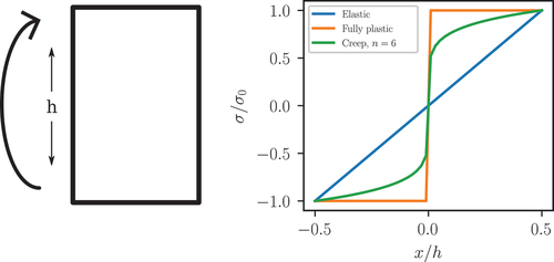
The section factor characterizes the amount of stress redistribution in a simple beam. The section modulus relates the maximum stress in the beam to the bending moment
The section factor is then the ratio of the section modulus for a linear elastic beam to the section modulus for the same beam with some other constitutive response; for example, a given creep law
For a beam with a rectangular cross section, the elastic section factor is
For some allowable stress , the maximum allowable elastic bending moment per unit thickness is
For situations controlled by the time-dependent part of the allowable stress for a rectangular section, the current ASME rules include a section factor of
accounting for stress redistribution caused by creep. Including this section factor, the permissible moment is
By contrast, the new proposed rules would allow for a fully plastic stress redistribution with section factor . However, the pseudoyield stress definition also includes the
factor accounting for the difference between the von Mises stress and the stress intensity. With the new method, this section has a maximum permissible moment of
As and
, the new approach allows for slightly more stress redistribution than the current ASME rules, providing a slightly more efficient design.
In this case, the component does not have multiple redundant load paths in the classic structural sense, just the ability to redistribute the initial elastic bending stress distribution. For cases with actual fully redundant load paths, the new approach can provide significantly more efficient designs than the current ASME rules, as the EPP analysis method can redistribute stresses beyond the simple bending section redistribution in the current design by elastic analysis rules. This means that for complex components, the new approach tends to provide more efficient designs when compared to the current rules.
III.C. Thermal Gradients and Peak Stress
describes a simple geometry relevant to microreactor components and tube sheets in shell-and-tube heat exchangers. The geometry consists of an infinite array of holes in a two-dimensional plane strain plate. The problem fixes the surface temperature of adjacent holes to different temperatures and
. A steady-state heat transfer simulation provides the temperature field across the entire periodic array. The thermal expansion due to the steady-state thermal gradient between the two holes provides a secondary stress proportional to
. The applied traction
in one direction provides a primary stress.
Fig. 3. Sample geometry of a plane strain plate with an array of holes. The black line shows the stress classification line used to calculate the design life via the current ASME rules. The inset shows the periodic unit cell used in the thermal and mechanical simulations as well as typical results from thermal and structural simulations.
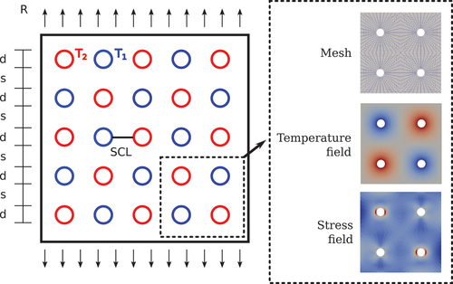
For this example, the plate material is Grade 91 steel and the reference temperature is . CitationReference 10 includes the minimum creep rate constitutive model required to execute the local check for Grade 91 steel. The examples keep the hole diameter constant at d = 25.4 mm and vary the hole pitch.
To analyze the problem, we constructed a parametric finite element model of a sufficient unit cell, shown in . Steady-state heat transfer analysis provides the design temperature field, and the analysis uses the same mesh for the FEA for both the global and local checks.
There are three parameters of interest in this problem:
primary stress controlled by
secondary thermal stress controlled by
peak stress controlled by the d/s ratio where s is the separation between the holes.
The examples here fix two of these three parameters and vary the third. The parameters R = 70 MPa, , and s = 101.6 mm (d/s= 0.25) define the reference case used as the starting point for all three examples. The design problem considers the maximum permissible design life for the structure considering the following:
ASME service load primary load design rules, assuming the loading conditions are part of a single service level A load
global service check of the new preliminary design rules
local service check of the new preliminary design rules.
The overall allowable design life of the component according to the proposed rules is the lesser of the lives from checks number 2 and 3.
We constructed the problem to make the ASME stress classification straightforward along the direct line between the holes shown in . The primary membrane stress is
The wall-average temperature along this stress classification line is always for any value of
. In the current ASME rules, the secondary and peak stresses do not contribute to the primary load design, and therefore the design life allowed by the current ASME rules is the time at which
plot the results of each the three studies. Specifically, plots the comparison between the new ASME rules as the primary load increases, plots the results as the secondary thermal load increases, and plots the results as the stress concentration increases.
Fig. 4. Results of the design study on the plate with hole geometry: (a) difference in allowable design life as a function of primary load level, (b) difference in allowable design life as a function of thermal stress, and (c) difference in allowable design life as a function of d/s.
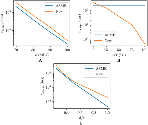
demonstrates three key trends in comparing the ASME rules to the new approach:
For components with low or moderate thermal stresses and low or moderate peak stress, the new approach allows for a consistently more efficient design than the current ASME rules. The ability of the EPP analysis to more efficiently redistribute load accounts for this increased efficiency.
The current ASME primary load design rules do not account for thermal stress. The new approach can account for high, detrimental thermal stresses with a simple design approach sufficient for preliminary design studies.
For stress concentration and peak stress, the new approach implements a trade-off when compared to the current ASME primary load design rules. The EPP and the simplified inelastic analyses allow the component to distribute load around a stress concentration more efficiently than a linear elastic analysis. On the other hand, the current ASME load classification approach allows designers to ignore peak stress in the primary load limit evaluation. Depending on the geometry, the new approach may provide more or less conservative designs than the current ASME primary load rules.
III.D. General Assessment of the New Approach
The three conclusions from the design study in Sec. III.C generally hold true for a wider variety of design problemsCitation12: (1) the new approach tends to produce more efficient designs than the current ASME rules for simple structures loaded mostly with primary/pressure stress, (2) the new method accounts for thermal stresses in the preliminarily design stage, whereas the current ASME primary load design rules do not, and (3) the new rules more accurately account for the effect of stress concentration early in the design process compared to the current ASME approach. Additional verification design studies, presented in Sec. III, note that the new approach better handles severe stress concentrations by screening out poor designs early in the design process. For example, in the plate-with-holes problem considered previously, the current ASME rules would use the same primary stress in the primary load allowable to check for circular holes, elliptical holes, or even sharp cracks. By contrast, the new design method would account for the difference in stress concentration factors between these different cases, for example, correctly screening out designs with sharp cracks.
The current Section III, Division 5, ASME rules do account for secondary and peak stress. However, they include these effects in the detailed strain accumulation and creep-fatigue rules, which are not well suited for preliminary design studies. One advantage of the current approach is that it accounts for these effects early in the design process with a simple approach that can be easily automated in modern FEA postprocessors. These advantages make the new rules especially suited for the preliminary design of microreactor components with complex geometries and high thermal stresses.
IV. APPLICATION TO A HEAT PIPE–COOLED MICROREACTOR DESIGN
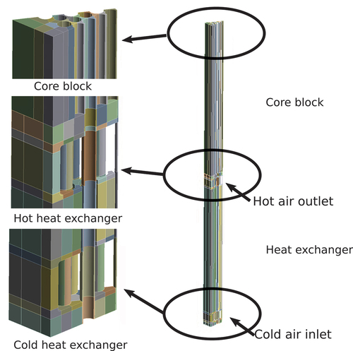
This section describes the application of the new preliminary design method to evaluate a heat pipe test article that is representative of an actual heat pipe–cooled microreactor. Electrical heating elements replace nuclear heating in the test article, but the test temperatures are representative of an actual operating reactor.
shows the test article geometry, which includes an electrically heated core block and an integrated heat pipe/air heat exchanger section. The Los Alamos National Laboratory provided the test article geometry and a set of steady-state operating thermal conditions to the authors. These thermal boundary conditions represent
heat generation from the electrical heating elements
heat transfer through the heat pipes
convective heat transfer between the heat pipes and air cooling in the heat exchanger
radiative heat transfer between the component and the environment and between component surfaces
thermal insulation installed on the test article.
Fig. 5. Overview of the complete finite element model of the test article. Details are called out in three critical areas: the core block, the hot end of the heat exchanger, and the cold end of the heat exchanger.
A steady-state heat transfer analysis provides the complete temperature field in the component based on these boundary conditions. The analysis also includes a bounding pressure of 20 barg in the heat pipes. This pressure is well above the expected normal operating pressure in the heat pipes at these conditions, but still too small to significantly influence the subsequent structural analysis.
The actual test article is constructed from 316L stainless steel. The design analysis used assumed material properties for 316H stainless steel, as that is the qualified ASME Section III, Division 5, Class A material with properties available in the current Code. CitationReference 10 includes the minimum creep rate model required to execute the local check for 316H stainless steel. All other required material properties are from the 2019 edition of the ASME Boiler & Pressure Vessel Code. This assumption means the design analysis here is somewhat optimistic, as the high-temperature creep strength of H-grade 316 stainless steel exceeds the strength of the L-grade.
The preliminary design analysis applied the method described in Sec. II. The analysis considers both the global and local service checks. The design evaluation includes the entire component, but the discussion here focuses on three key areas:
a representative section of the core block
a region representing the hot side of the heat exchanger
a region representing the cold side of the heat exchanger.
The test article passes the global service check for design lives greater than 300 000 h, the limit of the material data in the 2019 edition of the ASME Code. This reflects the very low pressure in the heat pipe–cooled design. This low pressure means primary load criteria do not limit the component design life, either using the current ASME rulesCitation14 or the global service check of the new method described here. That is, we would expect the allowable design life of this component, as evaluated with the current Code rules, to be effectively unlimited.
However, the local service check limits the test article design life to approximately 100 000 h. plots the creep damage from the local check. Critical locations that accumulate significant damage include the web between the heating elements in the core block and the stress concentrations at the corners of the heat exchanger.
Fig. 6. Fringe plot of the creep damage calculated in the component according to the local service check criteria at 100 000 h. Red regions are near a damage fraction of D = 1, indicating the design life for the component is around 100 000 h.
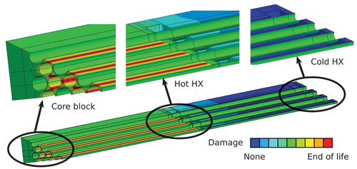
This design evaluation illustrates the key benefits of the new design approach when designing microreactor components:
The analysis approach considerably simplifies the design process when compared to the full ASME rules. In particular, selecting appropriate stress classification lines for complex components is extremely difficult and the classification/linearization process cannot be easily automated. The new design approach will be particularly advantageous for preliminary design studies, as it can be automated for high-throughput evaluation of many different potential design concepts.
Design methods that do not consider thermal stresses are not suited for the preliminary design of components for many microreactor concepts where the system pressures are very low but the thermal stresses are high. The full ASME design rules, including the strain accumulation and creep-fatigue design rules, capture the detrimental impact of thermal stress and stress concentration on the test article design.Citation14 However, these rules are extremely complicated and time consuming to execute, more suited for a final, formal design evaluation. The new method described here accounts for these effects while remaining simple enough for preliminary design studies.
The current ASME primary load design rules for preliminary design do not account for cyclic loading effects. This can produce unrealistic preliminary designs for components that experience substantial numbers of service cycles. While the new method described here does not rigorously account for cyclic effects, by incorporating secondary and peak stresses into the preliminary analysis, the approach can at least screen out designs that are grossly unsuited for cyclic service.
V. CONCLUSIONS
This paper describes a new design method for high-temperature reactor structural components. The design approach simplifies the current Section III, Division 5, ASME rules for the primary load design of high-temperature reactor components while retaining key connections to the current ASME design data. Designers can analyze components and automate the design calculations for the new method in FEA software. The approach accounts for thermal stresses and stress concentrations, whereas the current ASME rules account for these effects only late in the design process. These features make the new method especially suitable for the preliminary design of high-temperature microreactor components, where systems often have low pressures, high thermal gradients, complex geometries, and undergo extensive load cycling.
This paper describes a simplified version of the full approach developed for consideration at ASME. These simplifications result in a method suitable for fast preliminary design of complex components. Several examples illustrate key features of the new design approach: its confluence with the current ASME rules for typical pressure vessel components, how the new approach leads to more efficient designs via better representation of stress redistribution through creep and plasticity, and how the new approach successfully captures the detrimental effect of thermal stress early in the design process. A final example applies the design method to evaluate a heat pipe thermal test article representative of the thermal conditions in a heat pipe–cooled microreactor.
ASME is currently considering the full version of the design method for adoption into the Boiler & Pressure Vessel Code as a Nuclear Code Case. After adoption, the method could be used to satisfy the ASME primary load limit criteria in addition to serving as a preliminary design tool for reactor vendors and designers.
Acronyms
| ANL: | = | Argonne National Laboratory |
| ASME: | = | American Society of Mechanical Engineers |
| CRBRP: | = | Clinch River Breeder Reactor Program |
| DOE: | = | U.S. Department of Energy |
| EPP: | = | elastic perfectly plastic |
| FEA: | = | finite element analysis |
Nomenclature
| = | = time-dependent allowable stress guarding against creep rupture, tertiary creep, and excessive creep deformation, as well as plastic collapse and yielding. | |
| = | = minimum stress to rupture guarding only against creep rupture. | |
| = | = time corresponding to a rupture stress of S and a local temperature T using the ASME Code minimum stress to rupture data. |
Acknowledgments
The authors gratefully acknowledge discussions on the test article design with Holly Trellue, Robert Reid, Lindsey Gaspar, and Katrina Sweetland, all of the Los Alamos National Laboratory.
This paper has been co-authored by UChicago Argonne LLC under contract no. DE-AC02-06CH11357 and by Battelle Energy Alliance under contract no. DE-AC07-05ID14517 with the U.S. Department of Energy (DOE). Programmatic direction was provided by the Office of Nuclear Reactor Deployment of the Office of Nuclear Energy, DOE. The U.S. government retains and the publisher, by accepting the paper for publication, acknowledges that the U.S. government retains a nonexclusive, paid-up, irrevocable, world-wide license to publish or reproduce the published form of this paper, or allow others to do so, for U.S. government purposes. The DOE will provide public access to these results of federally sponsored research in accordance with the DOE Public Access Plan: (http://energy.gov/downloads/doe-public-accessplan).
Disclosure Statement
No potential conflict of interest was reported by the authors.
Notes
a The difference between a secondary and a peak stress is largely historical. A peak stress is caused by a stress concentration, i.e., a feature that would not be included in a traditional shell model of a vessel.
References
- A. Q. GILBERT and M. D. BAZILIAN, “Can Distributed Nuclear Power Address Energy Resilience and Energy Poverty?” Joule, 4, 9, 1839 (2020); http://dx.doi.org/10.1016/j.joule.2020.08.005.
- A. PEAKMAN, Z. HODGSON, and B. MERK, “Advanced Micro-Reactor Concepts,” Prog. Nucl. Energy, 107, 61 (2018); http://dx.doi.org/10.1016/j.pnucene.2018.02.025.
- “Boiler and Pressure Vessel Code,” American Society of Mechanical Engineers (2019).
- A. K. DHALLA, “Recommended Practices in Elevated Temperature Design: A Compendium of Breeder Reactor Experiences (1970–1987): Volume II—Preliminary Design and Simplified Methods,” WRC-363, Welding Research Council (1991).
- R. I. JETTER and M. H. JAWAD, “Design and Analysis of ASME Boiler and Pressure Vessel Components in the Creep Range,” American Society of Mechanical Engineers (2009).
- D. OWUSU, M. R. HOLBROOKE, and P. SABHARWALL, “Regulatory and Licensing Strategy for Microreactor Technology,” INL/EXIT-18-51111, Idaho National Laboratory (2019).
- H. A. GABBAR, M. R. ABDUSSAMI, and M. I. ADHAM, “Micro Nuclear Reactors: Potential Replacements for Diesel Gensets Within Micro Energy Grids,” Energies, 13, 19, 5172 (2020); http://dx.doi.org/10.3390/en13195172.
- P. CARTER, R. I. JETTER, and T.-L. SHAM, “Application of Elastic-Perfectly Plastic Cyclic Analysis to Assessment of Creep Strain,” Proc. ASME Pressure Vessels and Piping Conf., Toronto, Ontario, Canada, p. 749, American Society of Mechanical Engineers (2012).
- P. CARTER, R. JETTER, and T.-L. SHAM, “Application of Shakedown Analysis to Evaluation of Creep-Fatigue Limits,” Proc. ASME Pressure Vessels and Piping Conf., Toronto, Ontario, Canada, p. 761, American Society of Mechanical Engineers (2012).
- M. C. MESSNER and T.-L. SHAM, “Initial Development and Verification of a Primary Load Design Method Based on Elastic-Perfectly Plastic Analysis,” ANL-ART-201, Argonne National Laboratory (2020).
- A. ROVINELLI et al., “Accurate Effective Stress Measures: Predicting Creep Life for 3D Stresses Using 2D and 1D Creep Rupture Simulations and Data,” Integr. Mater. Manuf. Innovation, 10, 4, 627 (2021); http://dx.doi.org/10.1007/s40192-021-00228-1.
- M. C. MESSNER, R. I. JETTER, and T.-L. SHAM, “A High Temperature Primary Load Design Method Based on Elastic Perfectly-Plastic and Simplified Inelastic Analysis,” Proc. ASME Pressure Vessels and Piping Conf., V001T01A068, Minneapolis, Minnesota, American Society of Mechanical Engineers (2020).
- R. K. PENNY and D. L. MARRIOTT, Design for Creep, Springer Science & Business Media (2012).
- G. YE, M. MESSNER, and T.-L. SHAM, “Example Evaluation of a Representative Heat Pipe Test Article Design for Structural Acceptability Using ASME Design Rules,” ANL-ART-200, Argonne National Laboratory (2020).