
 ?Mathematical formulae have been encoded as MathML and are displayed in this HTML version using MathJax in order to improve their display. Uncheck the box to turn MathJax off. This feature requires Javascript. Click on a formula to zoom.
Abstract
Around the world, deep borehole disposal is being evaluated for intermediate level-waste (ILW), high-level waste, and spent nuclear fuel. To facilitate a disposal concept options analysis for ILW in Australia, desktop and lab-based geoscientific investigations, together with generic post-closure safety assessments of deep borehole disposal of long-lived ILW, have been undertaken. This paper reports on geoscientific data obtained on crystalline rock and rock salt as model rocks for geological disposal. Petrophysical and mineralogical properties for these rocks have been investigated to provide realistic data for evaluation and input to post-closure safety assessments.
For crystalline rock samples originating from depths between 700 to 1900 m, very low hydraulic conductivity (2 × 10⁻¹² to 3 × 10⁻¹¹ m/s) and very low porosity (0.02% to 1.2%) were obtained. The noble gas isotopic composition of fluid inclusions from the same depth interval confirmed the rock had been devoid of recent interaction with meteoric water, thus providing potentially suitable conditions for geological disposal. Rock salt from a 802-m (heterogeneous sample with 40% halite) and a 1100-m (sample with 98% halite) depth also had a low hydraulic conductivity (5 × 10⁻¹⁰ to 5 × 10⁻⁹ m/s at 802 m and 10−11 to 2 × 10⁻¹⁰ m/s at 1100 m) and very low porosity (~0.8% for the heterogenous sample and ~0.2% for the pure halite sample).
Post-closure safety assessments based on numerical modeling provided bounding conditions around the thermal evolution of the disposal environment in crystalline rock for low heat generating ILW (50 W per 180-L vitrified waste canister), including exploring the sensitivity of temperature evolution within the borehole and rock environment to parameters such as heat load, borehole depth, geothermal gradients, and rock thermal conductivity. The coupling of heat transport with radionuclide migration to account for buoyancy-driven transport was shown to have a limited impact on radionuclide migration.
For a disposal borehole in crystalline rock, the radionuclide concentrations and annual dose rates from key radionuclides (99Tc and 79Se) for a 500-m, 1000-m, or 3000-m deep borehole were negligible (i.e., many orders of magnitude smaller than the threshold dose the International Atomic Energy Agency considers insignificant for humans, 0.01 mSv/year). For disposal in rock salt, a suite of numerical model scenarios explored the effectiveness of the engineered barriers, including the glass matrix, primary package, and overpack, assuming diffusion-dominated transport. These scenarios illustrated that the performance of the disposal system was insensitive to the presence or absence of engineered barriers, as dose rates at late time (>105 years) were nearly identical for all scenarios.
These results indicate that the natural barrier provided by the salt is very effective at containing radionuclides, while the engineered barriers serve mainly to delay the arrival of the peak dose. While the results are preliminary, the post-closure safety assessments, supported by measured data from crystalline rock and rock salt, give confidence that deep borehole disposal of long-lived ILW would result in dose rates considered insignificant for humans within a few meters from the borehole.
I. INTRODUCTION
Deep borehole disposal (hundreds to thousands of meters in depth) is being considered around the world for high-level waste (HLW), spent nuclear fuel, separated plutonium wastes, some very high specific activity fission-product wastes, and long-lived intermediate-level waste (ILW).[Citation1–6] In Australia, ILW from research reactors and radiopharmaceutical production represents the principal waste stream that requires deep geologic disposal.[Citation7,Citation8] While the Australian government has not yet made a decision on its preferred strategy for ILW disposal, it is anticipated that deep borehole disposal of small volumes of appropriately conditioned ILW would be a more cost-effective, and modular, solution compared to a conventional geologic disposal facility. In addition to these considerations, deep borehole disposal could be considered (1) to remove a problematic waste stream from co-disposal in a geological repository (e.g., high-burnup or high-enriched fuels), (2) to achieve early disposal in crisis situations, (3) more economic than a conventional mined geological repository for smaller waste volumes, and/or (4) to offer greater flexibility in co-disposal of small volumes of different waste types (HLW, ILW) in a single borehole.
Australia, through its National Science Agency, the CSIRO, has been evaluating, among other concepts, deep borehole disposal as a potential solution for its long-lived ILW. The project aims to demonstrate by means of a comprehensive research development and demonstration (RD&D) program the technical feasibility and the long-term safety of deep borehole disposal of appropriately conditioned long-lived ILW. The RD&D activities required to demonstrate technical feasibility include surface handling and full-scale field testing of waste/seal emplacement capabilities in one or two demonstration boreholes whose dimensions are nominally put at a maximum bottom hole diameter of approximately 0.6 to 0.7 m (or 26 to 7.5 in.) with a maximum depth of approximately 2000 m.[Citation9] Generic pre- and post-closure safety assessments and safety case development have commenced with consideration of crystalline rock, clay, and rock salt as potential host rocks.[Citation10–12] While pre-closure safety analyses are an integral part of demonstrating repository safety,[Citation13,Citation14] they are beyond the scope of the current paper.
A framework for streamlining the deep borehole RD&D activities was previously defined with safety, feasibility, and confidence enhancement statements specific for deep borehole disposal.[Citation9] Safety statements were developed that aim to underpin confidence in the long-term safety of deep borehole disposal. Feasibility statements being considered will support the claim that a deep disposal borehole can be constructed to meet the unconventional depth-diameter requirement, waste can be safely emplaced with manageable risk for e.g., stack containers, and that the borehole can be sealed in a manner that meets operational and long-term safety requirements.[Citation15,Citation16] Confidence enhancement activities will further support the safety case with both qualitative and quantitative evidence as per the Nuclear Energy Agency safety case framework[Citation17] and its adaptations for deep borehole disposal.[Citation4,Citation14] A system of traffic lights was used to illustrate the progress in each of these activities.
To facilitate preliminary and generic post-closure safety assessments of deep borehole disposal of long-lived ILW as part of a disposal concept options analysis, desktop and lab-based geoscientific investigations have commenced. The objectives of this paper, therefore, are to present a comprehensive overview of the recent geoscientific investigations that have been undertaken to underpin the preliminary and generic post-closure safety assessments for deep borehole disposal of long-lived ILW in Australia, in addition to providing a summary of the results from deep borehole safety assessments for crystalline rock and rock salt. This includes novel enabling tools and methods that assist with site screening, including rock characterization studies involving the noble gas isotopic composition of fluid inclusions from deep rock samples to interpret provenance and residence time of fluids within a potential host rock.[Citation18,Citation19]
Further geoscientific studies aim to provide realistic rock properties for evaluation and input to post-closure assessment models; to this end, petrophysical, mineralogical, and geomechanical properties for crystalline rock and rock salt have been investigated.[Citation20–22] Radionuclide sorption behavior to smectite clay has been studied using molecular dynamics simulations (MDSs).[Citation23] To provide bounding conditions around the thermal evolution of the disposal environment, heat transport calculations explored the sensitivity of temperature evolution within the borehole and rock environment to parameters such as heat load, borehole depth, geothermal gradients, and rock thermal conductivity.[Citation10] Preliminary post-closure safety assessments tested the need to consider coupled heat flow processes for heat loads ranging from low (50 W/canister) to high (500 W/canister HLW).[Citation12]
We further report a summary of the key findings from numerical evaluations of borehole mechanical stability for crystalline rock under a range of stress conditions.[Citation24,Citation25] Additional capability development not discussed in the current paper includes geological fault network analysis and improved representation of seismic fault conceptualizations in numerical models[Citation11,Citation26,Citation27] and materials research to test metal-based coatings regarding their corrosion and abrasion resistance for use on disposal overpacks for deep borehole disposal.[Citation28]
II. HOST ROCK PROPERTIES
II.A. Crystalline Rock
The safety strategy for the deep disposal borehole includes the safety function delay and attenuation (diffusion and retention) of radionuclide releases[Citation13] (sometimes referred to as the R safety function).[Citation9,Citation29] This requires demonstration of diffusion-dominated transport for a potential host rock (i.e., absence of natural groundwater flow)[Citation30] and demonstration that the host rock has been isolated from recent groundwater for a timescale commensurate with the timescale to attenuate radionuclides to negligible levels.[Citation31]
A set of nearly 40 core samples were obtained from a nearly 2-km-deep geothermal borehole located within the Mesoproterozoic Hiltaba Suite granites of the Northern Gawler craton (South Australia). Prior to the petrophysical laboratory tests, the mineralogy along the full Blanche-1 drill core was derived from the automated evaluation of spectral data acquired with the Hylogger-3TM system using infrared spectroscopy logging of the core surface. Data were acquired at the Geological Survey of South Australia Drill Core Reference Library.[Citation32] Supplementary mineralogy was obtained from X-ray diffraction on ground, powdered offcuts from granite samples.[Citation33] Finally, the specific surface area was determined using sorption of ethylene glycol monomethyl ether.[Citation34]
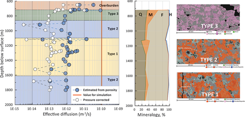
Thin section analysis with the quantitative Tescan Integrated Mineral Analyzer (TIMA) at CSIRO’s X-ray and Electron Beam Laboratory revealed three broad types of mineral alteration along the investigated core section from a 720-m to an approximately 1900-m depth (). An almost binary composition dominated by quartz (36%) and fine-grained muscovite (31%) was observed for Type-3 mineral alteration. Type-2 alteration showed predominantly the original quartz (28%) and feldspars dominated by microcline and albite (55%) with little alteration into clay minerals, such as illite. Alteration Type-1 had about 30% quartz and 64% feldspar. The mineral alterations are indicative of tectonic stress and hydrothermal water circulation, mostly in the shallower and in the deeper part of the granite core.[Citation19,Citation21]
Fig. 1. (left) Depth dependency of porosity-derived effective diffusion coefficient and pressure-corrected porosity on granite samples from the Hiltaba Suite, South Australia. (middle) Variation of mineralogy with depth (Q is quartz, M is muscovite, F is feldspars, and H is hematite). (right) TIMA analysis of thin sections for three types of mineral alteration groups.
Based on crystalline rock samples as a model rock for generic post-closure safety assessments, the petrophysical properties (permeability, porosity) were determined across the 2-km-deep borehole.[Citation20,Citation34,Citation35] A key feature of a suitable host rock for borehole disposal is to have a very low permeability resulting in diffusion-dominated radionuclide transport, such that the containment of radionuclides is secured for a sufficiently long time. A global review of site selection criteria for geologic disposal facilities reported host rock hydraulic conductivity on the order of 10−12 to 10−11 m/s as suitable.[Citation36]
Rock hydraulic conductivity is an important input parameter for post-closure safety assessments carried out with numerical models of flow and transport to estimate the radionuclide migration from the disposal zone into the surrounding host rock and geosphere.[Citation4,Citation14] To this end, hydraulic conductivity and porosity measurements on 2.5-cm (1-in.-) diameter and 5.0-cm (2-in.) long granite rock samples from a 700- to 1900-m depth have been undertaken using an automated AP 608 nitrogen Permeameter-Porosimeter (Coretest Inc). Based on an average rock density of 2.6 g/cm3, the in situ lithostatic stress at the sampling depths ranged from 18.8 MPa at 722 m to 50.2 MPa at 1931 m.
To test the stress-sensitivity of the rock, the porosity and hydraulic conductivity of each of the core samples were measured at eight increasing confining pressures up to 2500 psi (17.23 MPa), or 10% before the expected in situ lithostatic stress of the shallowest retrieved sample to avoid mechanical damage of the samples.[Citation20,Citation34] Although the applied confining pressures did not reach the in situ lithostatic pressures, the pressure range was sufficiently large to detect any stress sensitivity of the rock fracture network and the resulting porosity and hydraulic conductivity.
The results of the petrophysical measurements at 17.23 MPa confining pressure (slightly less than the in situ lithostatic pressure at an approximately 722-m depth of 18.8 MPa) showed very low permeabilities of around 0.5 to 7.5 micro-Darcy (μD) (hydraulic conductivity 2 × 10⁻¹² to 3 × 10⁻¹¹ m/s) with very low porosities in the range of 0.02% to 1.2%. The results further showed that porosity and hydraulic conductivity increased, with the rock fractures becoming more stress sensitive for samples that exhibited significant mineral alterations of feldspars into muscovite or illite clays.[Citation34,Citation35] The samples with higher fractions of muscovite and illite clays (Type-3 alteration) had a higher specific surface area (24 m2/g) than the unaltered samples (5 to 6 m2/g) (Type-1 and Type-2). As the mineral assemblages had been recorded across the full depth of the borehole and at high spatial resolution using the Hylogger-3TM system, mineral signatures were used to divide the borehole profile into three types with different degrees of alteration that may exhibit different degrees of delay and attenuation of radionuclides ().
The porosity values were subsequently used to calculate the effective diffusion coefficient De (m2/s) using the relationship
with the exponent = 4/3 corresponding to the model of Millington and Quirk (MQ),[Citation37] and D0 being the diffusion coefficient of radionuclides in the free pore fluid (m2/s). Note that the exponent
= 4/3 was derived for an ideal porous medium, and therefore should be applied with care, especially for rocks characterized by pore cementation, anisotropy, and very low connected porosity.[Citation37] A comparison between De values predicted with EquationEq. (1)
(1)
(1) and measured De values for a range of rocks and porosities is provided in Sec. II.B. For the purpose of this analysis, D0 was assumed to take a constant value of 2.2 × 10⁻⁹ m2/s, although in reality it is temperature dependent, and therefore increases with depth due to the geothermal gradient. The temperature effect is considered further in Sec. II.B.
Diffusion coefficients thus calculated from approximately 700 m, down to a 1900-m depth, are shown in . As the porosity was shown to be a stress-dependent parameter, and values reported in this study are for a maximum confining pressure of 17.23 MPa, i.e., slightly less than the assumed in situ confining pressure 18.8 MPa at 722 m, all porosity values should be updated to reflect the effect of the in situ confining pressure. A porosity-effective stress (effective stress = confining pressure − pore pressure) relationship for the current rock samples previously determined was used to correct the porosity values according to the assumed in situ lithostatic pressure at their sampling depth,[Citation34]
where P is the effective stress (psi).
Based on EquationEq. (2)(2)
(2) , all porosity values were corrected using in situ lithostatic pressures corresponding to their sampling depth. These rescaled porosities were subsequently used to recalculate the effective diffusion coefficient [assuming EquationEq. (2)
(2)
(2) is valid across all depths, which in itself is a simplification]; De values across the full depth profile are now about an order of magnitude lower, as can be observed in . Also shown in is the De value of 10−10 m2/s previously assumed for the generic safety assessments in crystalline rock.[Citation12] The current results demonstrate that both the uncorrected and pressure-corrected De are smaller than the generic De value used for modeling; in other words, as De values used previously[Citation14] were conservative, previous radionuclide impacts were conservative too.[Citation12] Note that De values were not temperature corrected,[Citation12] however even with a fivefold increase over a 3-km depth due to the temperature increase, it would still be conservative (for temperature effect on De see Sec. II.B).
A second, independent method to confirm diffusion-dominated radionuclide transport at the disposal zone is to use environmental tracers.[Citation31] This gives confidence about how long the rocks have been isolated from the water cycle (absence of any recent groundwater flow) and their potential suitability for geological disposal. A typical challenge associated with hard rocks, such as granites, is their very low porosity with insufficient pore fluid for conventional tracer sampling and analysis. The only solution to collect environmental tracers is to isolate mineral fluid inclusions and extract tracers, such as the noble gases helium, neon, and argon, for their isotopic ratio analysis.[Citation18,Citation19] The two most common approaches to extracting noble gases from fluid inclusions in mineral grains is by mechanical crushing or the use of heat.[Citation38] In this study, noble gases were analyzed from hand-picked and chemically cleaned granite grains (0.85 to 1 mm) and quartz grains of 1 to 2 mm (total sample weight between 1.1 to 2.5 g). After loading the grains into a high-vacuum crushing device, the crushing of the grains with a 10-ton press released gases from the fluid inclusions into the noble gas preparation line followed by the measurement of noble gas content and isotopes.
The results of the 20Ne/22Ne and 21Ne/22Ne (nucleogenic) and 40Ar/36Ar (radiogenic) isotope ratios from fluid inclusions in quartz grains isolated from whole granite samples showed a clear indication of an increasing nucleogenic neon (21Ne/22Ne) component with depth; typically, the greater the nucleogenic or radiogenic component, the older the fluid. By comparison, all Australian groundwaters originating from both shallow and deep basins for which noble gases have been measured by CSIRO have had 20Ne/22Ne (~9.8) and 21Ne/22Ne (~0.03) isotope ratios very similar to atmospheric ratios, which are significantly different from those in the fluid inclusions (~7.9 and ~0.06).[Citation18] The increasing nucleogenic contribution with depth is indicative of very old fluid components, supporting the hypothesis that the rock has experienced long-term isolation from the surficial water cycle.[Citation19]
The previous independent lines of evidence, i.e., (1) direct measurement of permeability at core scale, (2) estimation of effective diffusion from porosity measurements at core scale, and (3) noble gas isotope analysis on fluid inclusions obtained from quartz grains, provide support for a hydrogeological conceptual model of the Hiltaba granite in which fluid flow was virtually absent owing to porosities of typically less than 1%, with permeabilities as low as 0.5 μD(hydraulic conductivity 2 × 10⁻¹² m/s) and (uncorrected for in situ pressure) effective diffusion coefficients in the of range 10−12 m2/s or less. Using the noble gas isotope ratios of 21Ne/22Ne from fluid inclusions as indicators of, among others, evolution and the age of geofluids, this pore network is likely to have been devoid of meteoric water for extended timescales.
In this context, it is noteworthy that the Hiltaba suite granite was emplaced at ~1593.87 ±0.21 Ma as part of the regionally extensive Hiltaba Suite magmatism.[Citation39] This conceptual model will inform future post-closure safety assessment models in which the here reported flow properties will be used; in the current study, the petrophysical data are used to confirm that previous post-closure safety assessments using generic input parameters had been conservative (see Sec. III.A).
II.B. Rock Salt
Australia has significant salt deposits in several basins, with the most significant deposits comprising a minimum of several tens of meters of evaporites up to well intersections approaching 1 km. Extensive Proterozoic deposits occur in the Amadeus Basin (central Australia) and Officer Basin (eastern part of South Australia and southwestern part of Western Australia) with middle-Paleozoic deposits in the Adavale (southern Queensland) and Canning Basins. Salt mobilization is commonly observed in these basins with typical elements of salt tectonics, e.g., diapirism, welds, and salt walls.[Citation40]
Permeability and porosity data for rock salt were obtained from recent measurements on core samples from a Devonian salt diapir in the Canning Basin, Western Australia.[Citation22] Gas permeability (pulse-decay method with nitrogen gas) and porosity measurements were completed under multiple effective confining pressures up to 14 MPa. Porosity was obtained from a 1.5-in.-long homogeneous and relatively pure halite sample (98% halite) from a 1100-m depth (porosity ~0.2%) and a 1-in.-long heterogeneous sample (40% halite) from a 802-m depth (porosity ~0.8%). The shallower dolomite/quartz–rich and heterogeneous rock salt had a gas permeability of 50 to 500 μD (5 × 10⁻¹⁰ to 5 × 10⁻⁹ m/s), while the deeper nearly pure and homogeneous halite salt delivered a gas permeability of 1 to 20 μD (10−11 to 2 × 10⁻¹⁰ m/s).
These values were measured at 14 MPa effective confining pressure, slightly less than the in situ stress state of these samples (a lithostatic stress gradient of 23 MPa/km was considered). The lower porosity value is consistent with values of 0.1% to 0.2% reported for halite samples from the Waste Isolation Pilot Plant site[Citation41] loaded to 14.5 MPa confining pressure for 10 h. Geomechanical parameters, such as the quasi-static Young’s modulus, Poisson’s ratio axial, and radial deformation (creep), were obtained from multistage triaxial tests in order to study the impact of depth and anthropic stress perturbations during drilling on salt rock behavior and to predict the long-term creep response of the two salt facies.[Citation22]
In a way similar to what was discussed for the granite data, the effective diffusion coefficient for rock salt was estimated from porosity measurements by the application of the MQ model.[Citation37] In contrast with the MQ model, which assumes the exponent n in EquationEq. (1)(1)
(1) is equal to 4/3, measurements of
and porosity in a range of predominantly sedimentary rock types suggest n = 2.1 (best fit model with coefficient of determination r2 = 0.97, hereafter referred to as the Heather Sheldon or HS model[Citation42]; see ). It is interesting to note that the MQ model results in significantly higher values of
than the HS model for a given porosity, especially at the very low porosities relevant to transport in rock salt. For example, when
= 0.2%,[Citation22]
based on the MQ model is 117 times larger than that based on the HS model.
Fig. 2. Relationship between effective diffusion (expressed as De/D0 with D0 diffusion in free pore fluid) and porosity in various rock types.[Citation42] The MQ relationship (n = 4/3) is shown for comparison.
![Fig. 2. Relationship between effective diffusion (expressed as De/D0 with D0 diffusion in free pore fluid) and porosity in various rock types.[Citation42] The MQ relationship (n = 4/3) is shown for comparison.](/cms/asset/56df24a8-7cf7-4e53-8c6a-0c7ada82e742/unct_a_2266609_f0002_oc.jpg)
For deep disposal conditions, the temperature dependency of the diffusion coefficient of radionuclides in the free pore fluid, , must be accounted for. The temperature dependency follows an Arrhenius relationship[Citation43]
where
| = | diffusion coefficient at temperature | |
| = | temperature (K) | |
| = | activation energy (J/mol) | |
| = | 8.314472 J/K/mol is the universal gas constant. |
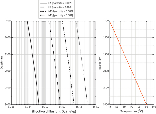
Three values of were derived, representing depths of 0, 1000, and 3000 m in a geothermal gradient of 20°C/km with a surface temperature of 30°C (representing conditions in the Frome Rocks, Western Australia).[Citation44] Assuming
= 30 kJ/mol,[Citation45]
m2/s, and
= 25°C, the corresponding values of
are
,
, and
m2/s at 500 (40°C), 1000 (50°C), and 3000 m (90°C), respectively.
The dependency of De on rock temperature for two values of porosity (0.002 and 0.008) and two tortuosity models (HS and MQ) is shown in . The temperature range shown is from 40°C at 500 m to 90°C at 3000 m. The temperature effect is the same for each of the four De models, as D0 is affected in the same way [see EquationEq. (3)(3)
(3) ]: D0 increases by a factor 4.9 between 500 and 3000 m. Increasing the porosity from 0.002 to 0.008 results in an increase of De by a factor 18.4 for the HS model, but only by a factor 6.3 for the MQ model. Owing to the greater exponent applied to the porosity in the HS model compared to the MQ model (2.1 versus 4/3), the HS model is more sensitive to porosity variations than the MQ model.
Fig. 3. Dependency of De on depth (via geothermal gradient, right plot), porosity and tortuosity models (HS and MQ).
III. POST-CLOSURE SAFETY ASSESSMENTS
III.A. Disposal in Crystalline Rock
The generic post-closure safety assessments first addressed the potential effect of heat released by the decaying waste on temperature conditions within the near field of the borehole and temperature-driven radionuclide transport owing to fluid density effects. Once the temperature conditions are described, radionuclide migration from a deep borehole using generic transport parameters is discussed. Because generic parameters are used, there is no specific location or area associated with the current migration calculations. The flow and transport parameters from the Hiltaba Suite borehole were given only for comparison with the generic parameters used in the generic post-closure safety assessment. As discussed in Sec. II.A, the generic parameters were clearly shown to be conservative. Future assessments will incorporate the site-specific petrophysical data, together with sorption data characteristic of the measured mineralogy.
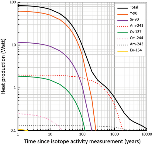
The performance of the engineered and natural barriers may be impacted by the temperature evolution in the borehole near field and surrounding rock environment. Increasing temperatures will result from a combination of the natural geothermal gradient and heat released from decaying waste. Higher temperatures will accelerate the corrosion of waste forms and metal-based containers[Citation46] and may degrade bentonite or cement-based borehole seals.[Citation47] To gain insights into the temperature evolution in the disposal borehole and rock environment as a function of applied heat load, disposal depth, and rock parameters (geothermal gradient, rock thermal conductivity), heat transport calculations were undertaken with TOUGHREACT[Citation48] for low-heat-producing ILW and compared with other heat-emitting wastes such as HLW.[Citation12] The heat production for individual colis standard de déchets vitrifies UMo (CSD-U) canisters of vitrified waste was calculated using the FISTPAC-II code[Citation49] based on the isotope composition of the waste. The heat load at T = T0 + 1 year was 84.78 ± 0.12 W/canister, which decayed to 54.44 ± 0.07 W/canister at T0 + 20 years. (T0 = time of isotope composition measurement) ().
Fig. 4. Calculated heat production for one CSD-U canister of vitrified ILW (research reactor fuel).
The conceptual model included disposal boreholes to three different depths (500 m, 1000 m, and 3000 m), with a disposal zone in the bottom 200 m of the hole. The assumed host rock was crystalline, overlain by weathered basement (25 to 100 m) and unsaturated regolith (0 to 25 m). The main purpose of these generic performance assessments was to quantify the transient behavior of the heat evolution at the disposal canister wall and within the host rock, and to evaluate if the temperature in bentonite seals that were at least 100 m separated from the heat source would exceed 100°C. The sensitivity of the temperature evolution with regard to the magnitude of the heat source was also tested using a hypothetical heat production of 500 and 1500 W/canister (representing HLW).
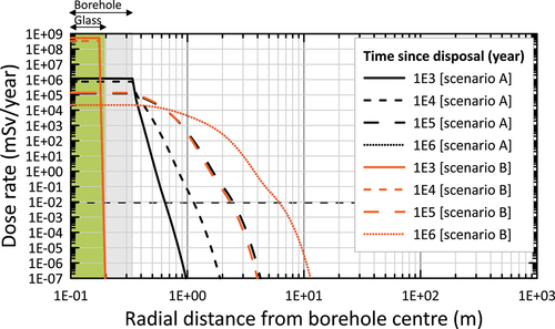
Based on geothermal gradients ranging from 18.2°C/km to 27°C/km () and a reference crystalline rock thermal conductivity of 2.5 W/m°C,[Citation12,Citation50,Citation51] the results confirmed that at none of the three disposal depths did the temperature in the bentonite seals ever reach 100°C. Moreover, the temperature in the bentonite remained at the depth-dependent in situ temperatures. Typical temperature evolutions for the low-heat-producing ILW (50 W per CSD-U canister, 100 canisters in one borehole) for the 1000-m-deep and 3000-m-deep disposal borehole (temperature profiles are shown at the middle of the 200-m-deep disposal zone, i.e., at a 900-m and a 2900-m depth), accounting for variations in geothermal gradient, are shown in . A sensitivity analysis further demonstrated that bentonite temperatures were insensitive to uncertainties in the rock thermal conductivity considering values between 1.7 and 4 W/m°C,[Citation10] which were representative of the lower and upper range of observations reported for igneous plutonic rocks.[Citation52,Citation53] The reference value of 2.5 W/m°C is representative for felsic (igneous) rocks at temperatures between 100°C and 200°C.[Citation14]
Fig. 5. (a) Conceptual representation of heat load from decaying ILW causing a thermal plume in crystalline host rock, and (b) geothermal gradients from Australian basins applied in the heat calculation.
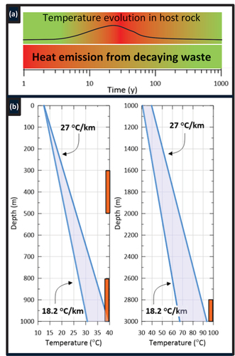
Fig. 6. (a) Calculated temperature evolution at disposal canister wall and within host rock at a 900-m depth and (b) At a 2900-m depth. Upper bound temperature for the 27°C/km gradient and lower bound for the 18.2°C/km gradient. Thermal conductivity of rock KR = 2.5 W/m °C.
For the 800- to 1000-m-depth and the 2800- to 3000-m-depth disposal zones, the temperatures at the canister wall and within the host rock increased by the same amount (). This is as expected in a very tight host rock, assuming all parameters relevant for heat transport are depth invariant. The absolute temperature, though, does increase as one moves deeper into the rock, with a greater temperature increase for the greater geothermal gradient. Based on a geothermal gradient of 18.22°C/km, the maximum temperature in the disposal zone (canister wall) at 900 m was about 36°C at the canister wall, decreasing to 33°C at 5 m and 31°C at 25 m into the rock (). At a 2900-m depth, the maximum temperature was about 85°C at the canister wall, decreasing to 82°C at 5 m and 80°C at 25 m into the rock (). At both depths, the bottom of the bentonite seal (100 m above the top of the disposal zone) never increased above the in situ temperature. This means that a bentonite seal at 100 m from the top of the disposal zone will remain at temperatures below 100°C.
Under the conditions of the greater geothermal gradient of 27°C/km, slightly higher temperatures were observed, with maximum values being approximately 8 deg higher at 900 m and 20 deg higher at 2900 m. The maximum temperatures in the bentonite seal were still below 100°C. For the hypothetical 500 W and 1500 W/can heat sources, the maximum temperatures at the canister wall at a 2900-m depth rose to approximately 130°C and 260°C, respectively (geothermal gradient of 18.22°C/km results not shown).
Next, coupled flow, heat, and radionuclide transport calculations were undertaken with a three-dimensional axisymmetric model implemented in TOUGREACT to assess to what degree of heat produced from the decay of radioactive waste initiates the buoyancy-driven migration of radionuclides from a deep disposal borehole.[Citation12] Radionuclide migration in the crystalline host rock was assumed to be only by molecular diffusion, as the conceptual model assumed the absence of a hydraulic gradient in the low-permeability rock; a vertical convective component was calculated due to a transient heat source associated with the decaying radioactive waste. The governing equation for solute transport in porous media is[Citation54]
where D0 was defined previously [EquationEq. (1)(1)
(1) ], and where
| Cj = | = | concentration of radionuclide j in the pore fluid (mol/m3) |
| Rj = | = | retardation factor accounting for adsorption/desorption |
| t = | = | time (s) |
| T = | = | tortuosity factor |
| α = | = | dispersivity (m) |
| v = | = | advective velocity (m/s) |
| Sj = | = | sink/source term [mol/(m3 s)] representing radioactive decay. |
The retardation factor Rj is given as
where ρs is the solid density (kg/m3) and Kdj (m3/kg) is the sorption coefficient for linear and reversible sorption.
The advective velocity v is defined as
where
| ϕ = | = | porosity |
| q = | = | groundwater flux (m/s) |
| K = | = | hydraulic conductivity (m/s) |
| i = | = | head gradient |
| k = | = | intrinsic permeability (m2) |
| ρw = | = | water density (kg/m3) |
| ν = | = | kinematic viscosity (m2/s) |
| = | pressure gradient [kg/(m2 s2)] (including the buoyancy effect). |
The heat transfer (thermal energy conservation) equation is defined as
where
| T = | = | temperature (K) |
| ρb, ρw = | = | bulk and water density [kg/m3], respectively |
| λ = | = | the (bulk) thermal conductivity [W/(m K)] |
| cb, cw = | = | bulk and water-specific heat [J/(kg K)], respectively |
| v = | = | advective velocity. |
EquationEquations (5)(5)
(5) , Equation(6)
(6)
(6) , and Equation(7)
(7)
(7) are coupled partial differential equations that link advection and convection.
Given the generic nature of the post-closure safety assessments, no biosphere model was developed to account for various potential exposure pathways, which would require assumptions about food consumption pathways (exposure due to ingestion) in addition to inhalation and external exposure pathways.[Citation55] The only exposure pathway considered was by uptake of drinking water containing radionuclides. To this end, radionuclide concentrations within the simulation domain were converted to dose rate (mSv/year) for an adult member of the public assuming a hypothetical consumption of 0.730 m3 of pore fluid (e.g., from a water well) annually[Citation56] and dose coefficients for ingestion.[Citation57]
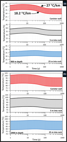
A limited set of radionuclides was considered for the purpose of illustrating how coupled heat-transport processes may affect long-term radionuclide migration. Only results for 79Se and 99Tc are discussed here; the results for additional radionuclides 137Cs, 239Pu, and 126Sn have been reported previously.[Citation12] The initial activity[Citation58] of 79Se and 99Tc was 1.74 × 10¹¹ and 1.03 × 10¹³ Bq, respectively. The radionuclide activities in this generic post-safety assessment in crystalline rock are based on the assumption that 100 CSD-U containers will be generated throughout the lifetime of the Australian research reactors HIFAR (the High Flux Australian Reactor, which ceased operation in 2007) and OPAL (the Open Pool Australian Light-water reactor, which commenced operation in 2006) at the Australian Nuclear Science and Technology Organization, Lucas Height, Sydney.
The temperature effects on the effective diffusion coefficient were not accounted for in this calculation, although a sensitivity analysis with a five times higher De was considered. Given the assumption of instantaneous dissolution for the source term, the temperature effects on radionuclide solubility could be ignored. Of the four heat sources included in the comparison, three had a short-duration heat output for about 200 years (50, 500, 1500 W/canister), while the fourth had a long-term heat output for more than 10 000 years (2200 W/spent fuel assembly).[Citation59]
Regardless of the depth of the disposal borehole (500, 1000, or 3000 m), a rock volume with a maximum radius of approximately 60 m surrounding the disposal borehole was influenced by the transient heat production for the 1500 W/canister, with buoyancy creating upward convective velocities one order of magnitude larger (~10−12 m/s) than the velocities at the 50 W/canister heat source (~10−13 m/s) (host rock hydraulic conductivity = 10−11 m/s). The transient nature of this buoyancy effect was limited to approximately 200 years, corresponding to the assumed duration of the heat pulse. During this transient phase, radionuclide migration was only minimally affected by the temporarily increased upward velocities, whose values did not exceed ~10−12 m/s, conditions at which transport would still be diffusion dominated. This resulted in slightly higher concentrations at observation points above the disposal zone for the highest heat source.
Even for the shallowest borehole (500 m), the radionuclide concentrations and annual dose rates were negligible and many orders of magnitude smaller than the dose the International Atomic Energy Agency (IAEA) considers insignificant for humans (0.01 mSv/year).[Citation60] This threshold for total dose was reached after a travel distance of 20 m from the source (), with nearly identical results at 105 and 106 years (50 W/canister).
Fig. 7. Calculated annual dose for (left) 79Se and (right) 99Tc for radionuclide release from a 200-m-long disposal zone (500-m-deep borehole) in crystalline rock. The dose threshold for the negligible effect of 0.01 mSv/year has the label −2 (values in log10 mSv/year).
Increasing the reference diffusion coefficient (De = 10−11 m2/s) by a factor 5 resulted in a much larger dose rate (~5 × 10⁻⁴ mSv/year), which was still low enough to be safe based on the cumulative dose from all considered radionuclides (239Pu, 79Se, 126Sn, and 99Tc). This result showed the sensitivity of the dose rate to the diffusion parameter under the conditions of the model, and the importance of accurately determining the influential parameters, like the effective diffusion for site-specific applications. The temperature dependency of the effective diffusion coefficient was not considered in this calculation, although adjustments can be made using EquationEq. (3)(3)
(3) . As a unique finding, coupling heat transport with radionuclide migration to account for buoyancy-driven transport was shown to have limited importance on migration, at least for the assumptions of this study.[Citation12]
III.B. Disposal in Rock Salt
The post-closure safety assessments for borehole disposal of vitrified waste from reprocessing of research reactor spent fuel in rock salt involved testing the contributions of different engineered barriers to radionuclide containment. A suite of scenarios was run to explore the effectiveness of the engineered barriers, including the impact of varying the longevity of the glass matrix, stainless steel primary package, and mild steel overpack, and the effect of varying diffusion parameters for rock salt. We report here on the results from a selection of the calculation scenarios. A full description of all calculation scenarios has been discussed previously.[Citation42]
A one-dimensional axisymmetric model was implemented in TOUGHREACT using the rock salt properties from Sec. II.B. The borehole disposal concept assumed that three vitrified waste containers (type CSD-U) would be combined in a 0.5-m-diameter and 5.6-m-long mild steel overpack with copper coating.[Citation28] With three CSD-Us per overpack, a total of 33 overpacks would be inserted vertically in the borehole to accommodate approximately 100 CSD-U containers with a proposed spacing of 0.4 m between the overpacks, giving a total disposal zone height of 198 m. The space around and between the overpacks would be backfilled with a suitable material (e.g., crushed salt or bentonite). The radionuclide inventory used in the migration calculations encompassed 13 actinides and their decay chains and nine fission and activation products, with a total inventory representative of 100 CSD-U containers.[Citation42]
The model represented the release of radionuclides from a waste package as it degrades due to chemical interaction with pore fluid from the surrounding rock. It was assumed these interactions would result in gradual degradation of the overpack, followed by degradation of the stainless steel canister, and finally dissolution of the glass. Radionuclide release and transport were evaluated based on a purely hypothetical exposure scenario in which a radiation dose was assumed from radionuclide ingestion that would be received by a person consuming groundwater from a hypothetical well receiving radionuclides from diffusive transport through the rock salt.
Sorption coefficients for rock salt[Citation61] were used for the radionuclides present in one of the long-lived ILW waste streams (vitrified waste from research reactor spent fuel); the midpoint of the range of values for () was used in the calculations. Note that values for Cm, Pa, Se, Sn, Zr, and Pd have been reduced by a factor of 10 to account for the effect of high salinity on sorption, consistent with previous approaches.[Citation61]
TABLE I Sorption Coefficients Kd on Rock Salt[Citation61]
Glass degradation is represented as a purely physical process, with its only impact being to increase the effective diffusion coefficient of the glass, thus enabling radionuclides to diffuse out of the glass. The chemical effects of degradation (e.g., changes in pore fluid chemistry or generation of degradation products, like iron oxides, that would provide additional adsorption) were not considered. In a disposal environment the radionuclides would be released from the glass matrix over a finite period due to the gradual degradation of the glass as it came into contact with rock porewater and/or groundwater.[Citation62–64]
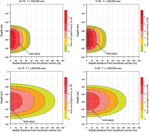
The dissolution process was greatly simplified by assuming that the glass could be represented as a porous medium, whereby the entire inventory of radionuclides was instantaneously dissolved in a hypothetical pore fluid within the glass at the time of disposal. The gradual release of dissolved radionuclides due to glass degradation was approximated by a gradual increase in the effective diffusion coefficient of the porous glass over a given period. This was achieved in TOUGHREACT by increasing the tortuosity factor τ, defined as
The porosity value for the backfill (crushed salt) was taken as 10% (0.1 m3/m3), which falls within the range for crushed salt.[Citation65] The glass and overpack were assigned porosities representing their degraded state from the beginning of the simulation (0.4 m3/m3 for both materials), and their tortuosity factors were adjusted with time to approximate the effects of degradation on the diffusion of radionuclides (further details follow).
The degradation of the stainless steel casing and overpack were represented by an instantaneous increase in the tortuosity factor of the overpack from approximately zero to its degraded value at the end of their combined degradation periods. Note that the 0.005-m-thick stainless steel primary package was not represented explicitly in the numerical mesh; hence, its barrier effect was represented by preventing diffusion in the overpack. The instantaneous increase in the tortuosity factor at the end of the degradation period can be justified if the primary package and overpack degrade gradually and uniformly from the outside, such that groundwater is unable to access the underlying material until complete degradation has occurred.
The glass degradation period was derived from the dissolution model previously reported.[Citation66] Those authors based their HLW glass dissolution model on lab and in situ tests undertaken with SON68 glass in Boom Clay (Belgium). A realistic conservative lifetime of 72 000 years was derived to completely dissolve the glass matrix. Two variant dissolution times were defined: a pessimistic one of 20 000 years and an optimistic one of 1 000 000 years. These dissolution times were derived for disposal in Boom Clay, considering an average rock temperature of 16°C.
As the glass dissolution time is temperature dependent,[Citation67] some correction of the glass dissolution rates may be required to represent disposal at higher background temperatures, while pH dependency must also be accounted for. Boom Clay has a pH of about 8,[Citation68] while most marine salt deposits are neutral or alkaline (seawater pH = 8.3 and increases with evaporation).[Citation69] In the absence of any site-specific pH values for salt, a value of 8 (the same as Boom Clay) was deemed appropriate to represent the conditions for disposal in salt. Given that all scenarios represent a background temperature of 50°C or more, which is considerably higher than the temperature that was used to derive the dissolution rates in Boom Clay, the pessimistic 20 000-year lifetime was used as a reference value, while 70 000 years was used as an optimistic value.[Citation66]
displays the time dependency of the porosity, tortuosity factor, and effective diffusion coefficient for the two glass dissolution times (20 000 and 70 000 years). The porosity increase was assumed to follow a power-law relationship. While experimental evidence for glass dissolution rates that could be used to calibrate the porosity evolution over such long timescales is lacking, the release rate from the glass, and thus the shape of the porosity versus time relationship, will be shown not to be an influential parameter on radionuclide migration.
Fig. 8. Time-dependence of porosity ϕ, tortuosity factor τ, and effective diffusion coefficient De for reference (20 000 year) and optimistic (70 000 year) glass dissolution periods, assuming the HS model for tortuosity and D0 at a 1000-m depth. The corresponding values for rock salt with a porosity of 0.2% are also shown.
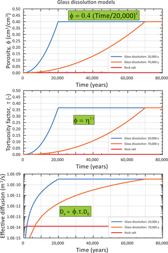
The first set of results compares radionuclide release for a model without any engineered barriers (scenario A) and a model with all three engineered barriers implemented (scenario B). In scenario B, the lifetime of the glass, stainless steel primary package, and overpack were assumed to be 20 000, 2500, and 100 000 years, respectively. In both scenarios, the porosity of the rock salt was set to 0.002 m3/m3 (representing the pure salt sample described in Sec. II.B) and the HS model for tortuosity was used. The model without engineered barriers (scenario A) is a conservative scenario where the engineered barriers are in their degraded state at the start of the simulation and all radionuclides are instantaneously dissolved and available for transport.
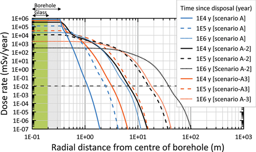
The model results are shown as total annual dose rates as a function of radial distance from the borehole at four times: 103, 104, 105, and 106 years (). The dose rate in the radial direction from the borehole center illustrates the limited sensitivity toward the effect of engineered barriers, especially at late times (>105 years). As the half-lives of the key radionuclides that contribute to the peak dose are all on the order of several hundred thousand years or greater (79Se, 99Tc, 107Pd, and 135Cs), an extremely long barrier lifetime would be required to effectively reduce the peak dose. Indeed, at 105 years, the dose rates for the two scenarios A and B are almost identical and at 106 years they have become identical (). An analysis of the spatial dependency of the dose rate clearly illustrates the very slow radionuclide migration in the salt rock, resulting in a maximum travel distance of the plume of less than 10 m (based on the 0.01 mSv/year threshold dose rate).
Fig. 9. Time dependency of the dose rate versus the radial distance from the borehole center for scenario A (without any engineered barrier, i.e., instantaneous dissolution of the glass and immediate release of radionuclides in the salt) and scenario B (all engineered barriers present). The dose rates for both scenarios are identical at 106 years.
The only difference between the results with the two very contrasting levels of engineered barriers in scenarios A and B is at early times, i.e., at 103 and 104 years. When all engineered barriers are present, assuming a 20 000-year dissolution time for the glass, all radionuclides still reside within the glass matrix (green shaded area in ). Without any engineered barriers (scenario A), the radionuclides have already migrated into the rock salt, be it for a very limited distance of approximately 1 m (based on the 0.01 mSv/year threshold dose rate).
Next the sensitivity of the dose rate to the conceptual model for the tortuosity (through its effect on the effective diffusion coefficient) and the porosity of the rock salt was tested. Using the HS relationship for tortuosity [exponent n = 2.1 in EquationEq. (1)(1)
(1) , scenario A] rather than the MQ relationship [exponent n = 4/3 in EquationEq. (1)
(1)
(1) , scenario A-2] results in slower spreading of radionuclides into the rock salt (). The greatest travel distance (about 40 m), defined as the distance where the dose rate reaches 0.01 mSv/year, is obtained with the MQ model with 0.002 m3/m3 porosity (scenario A-2). The HS model with 0.008 m3/m3 porosity (representing the impure salt sample described in Sec. II.B) reaches the next greatest distance at 106 years, i.e., just under 20 m (scenario A-3). The HS model with 0.002 m3/m3 porosity reaches the least far at 106 years, i.e., about 7 m (scenario A).
Fig. 10. Time dependency of the dose rate versus radial distance from the borehole center for scenario A (HS model with porosity = 0.002), A-2 1a (MQ tortuosity model with porosity = 0.002), and A-3 1d (HS model with porosity = 0.008).
Applying the widely used MQ relationship to estimate the tortuosity factor from porosity instead of using a more realistic relationship based on diffusion data from sedimentary rocks results in the significantly earlier arrival of the peak total dose rate and a four orders of magnitude reduction in the containment factor associated with 10 m of rock salt.[Citation42] The containment factor is defined as the ratio of the initial inventory to the cumulative flux or releases across an interface, and may be used as a performance indicator to measure the overall performance of one or a combination of engineered and natural barriers.[Citation42] Containment factors have also been calculated based on cumulative fluxes across two additional interfaces in the model: at the overpack-backfill interface and at the backfill-salt interface.[Citation42]
The MQ tortuosity model resulted in the largest travel distance of all the scenarios (40 m after 106 years). This result demonstrates the importance of using appropriate experimental data to constrain diffusion parameters in the relevant rock types, rather than relying on approximations implied by using generic models, such as the MQ model.
III.C. Containment Provided by Seals
Borehole seals contribute to the “isolation function,” the “limiting water ingress,” and the “slow transport due to diffusion and retention (adsorption)” safety functions.[Citation9] The long-term performance of clay-based and cement-based seals in a deep borehole environment has recently been reviewed.[Citation70] These reviews considered only slim investigation boreholes, without the complexities typical of a large-diameter disposal borehole (e.g., longer isolation/containment times required for waste disposal, interaction with heat production from decaying waste combined with the natural heat, etc.). Recent RD&D at CSIRO included laboratory investigations regarding gas transport through clay and the use of MDSs for the determination of diffusion parameters in bentonite.
Geological disposal of radioactive waste containing significant amounts of steel (waste material, waste package, overpack) is accompanied by the production of hydrogen gas, primarily a result of anaerobic corrosion of the metallic components.[Citation71–73] In the case of disposal in a borehole, the produced gas dissolves into the pore water, is transported away from the waste packages via diffusion, and accumulates in the drilling-damaged rock zone and/or at the interface with the ultra-low permeability seals (e.g., bentonite). If the rate of diffusion into the damage zone and/or the seal is inferior to the rate at which the gas is generated, the pore water will become oversaturated with the gas, a free-gas phase will form, and the local pressure will increase.[Citation71]
When the gas pressure is sufficiently high, gas will enter the damage zone and/or seals as a free-gas phase. For materials with high porosity and permeability, the gas entry pressure is typically low and enables dissipation of the increased pressure. For materials with low porosity and permeability, the gas entry pressure is much higher and may exceed lithostatic pressure. This carries the risk of creating new fractures in the material and/or extending existing ones, especially those created during borehole drilling.[Citation74,Citation75] To understand the potential for pressure buildup and the creation of fractures in seals that could compromise the integrity of the borehole, several experiments have commenced to characterize gas transport and breakthrough in clay using both He and H2 gas.
An investigation of radionuclide diffusion and adsorption in compacted bentonite used for borehole sealing was undertaken using MDSs and theoretical analysis methods. The effective De and apparent (Da = De/R, where R is the retardation factor accounting for adsorption) molecular diffusion coefficients of uranyl species in bentonite (Na+-smectite clay) were determined, including any dependency on clay pore size, density, and specific surface area.[Citation76] The results showed that both effective and apparent diffusion coefficients increased with the degrees of hydration and pore size. In contrast, the ratio between the effective and apparent diffusion coefficients behaved in an opposite way, i.e., decreasing with increasing pore size.
A further analysis of the De/Da ratio involved separating the geometric dependency (i.e., pore size) from the adsorption dependency. This revealed that the predominant mechanism causing the De/Da ratio to decrease with increasing pore size was a decrease of the adsorbed uranyl fraction.[Citation23] The effective and apparent diffusion coefficients were shown to be related by a fractional function of the specific surface area at a given clay pore size and surface area. The MDS-derived diffusion coefficients further showed an exponential decrease with increasing clay mineral density. The apparent diffusion coefficient had comparable values when compared with independent experimental data, although specific surface area, clay density, and pore size required careful consideration in the comparison. When MDS diffusion coefficients are upscaled to the macroscopic scale, they provide useful additional data to feed into radionuclide release calculation models for bentonite seals of geological repositories for radioactive waste.
IV. BOREHOLE STABILITY
Demonstrating the feasibility of drilling deep, large-diameter boreholes into hard rock involves an evaluation of borehole stability for a given rock type and local stress fields. Borehole instabilities often occur during drilling and may cause failure of the borehole wall due to rock breakage because of crack initiation and propagation in the direction of the maximum compressive principal stress. Especially in hard rocks, such as granite, explicit fracturing occurs. Borehole stability is critically important for the deep borehole disposal of radioactive waste. In addition to complicating the drilling operation, borehole failures may also impact the suitable depth available for waste emplacement and may create local temporal fracture networks that require specialized sealing materials to restrict radionuclide migration along the fractured borehole wall. Deep boreholes drilled to a 1000-m to 2000-m depth into crystalline rocks in Australia have been reported to have experienced borehole instabilities.[Citation74] Large-diameter boreholes, such as the one considered in the current study (bottom hole diameter of approximately 0.7 m), are particularly susceptible to borehole breakouts due to scale effects.
To assist with the design and planning of a deep, large-diameter borehole as part of a potential full-scale demonstration test for emplacement of dummy ILW disposal canisters, a 0.7-m-diameter borehole in crystalline rock has been modeled using FRACOD.[Citation24,Citation25] The two-dimensional (2-D) model considered horizontal cross sections of the vertical borehole at the depths of 1000 and 2000 m, with depth-dependent in situ stresses and rock temperatures based on field data.[Citation75] By varying critical FRACOD input parameters, including rock strength, in situ stress magnitudes, thermal cooling during drilling, and thermal heating owing to heat-producing waste, the effects of varying geological and disposal scenarios have been evaluated. The results showed that for the reference case using the most likely in situ stress magnitudes (σHmax/σV = 2.5; σhmin/σV = 1.5) and rock uniaxial compressive strength (UCS) = 180 MPa), very limited borehole breakouts were predicted at a 1000-m depth.[Citation25] At a 2000-m depth, noticeably more extensive borehole breakouts were predicted, some of which were up to 0.5 m deep into the rock ().
Fig. 11. Borehole breakout simulations in crystalline rock at a 2000-m depth using FRACOD. (a) High rock strength with UCS = 180 MPa, (b) Lower rock strength with UCS = 120 MPa, (c) Effect of drilling mud with lower temperature (27°C cooler) than rock temperature, and (d) Effect of existing rock fractures on breakout and rock permeability.
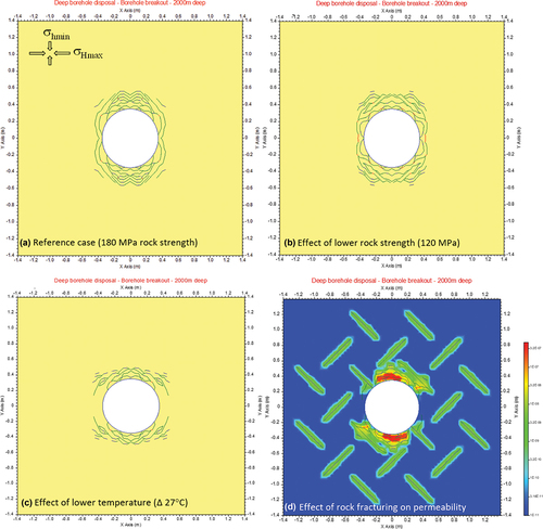
Preexisting fracture networks in the vicinity of the disposal borehole may propagate and coalesce with the new fractures initiated around the borehole; however, their effects are limited to within a distance of 0.5 m from the borehole wall (results not shown). As expected, a lower rock strength (120 MPa) produced larger borehole breakouts and a greater number of open fractures (). Short-term effects were predicted when drilling mud was used with a 27°C lower temperature relative to the in situ temperature, which causes a larger fractured zone with larger fracture apertures (). Finally, FRACOD also predicted increases to the equivalent rock permeability owing to fracture network generation, especially close to the borehole wall where permeability increased by nearly four orders of magnitude (). Future post-closure safety assessments will explore the effect of the increased permeability of the borehole wall on radionuclide migration.
To complement the borehole breakout studies on crystalline rock, similar simulations have been undertaken for shale rock.[Citation77] First, FRACOD was tested in its ability to reproduce the “log-spiral” fracture patterns observed in the laboratory using a small-scale borehole in shale. Under hydrostatic stresses, the FRACOD model reproduced the extensive shear-dominated fracture pattern. Subsequently, 2-D numerical simulations of borehole breakout in “strong” and “weak” shales were simulated with FRACOD in which 0.7-m-diameter vertical boreholes were considered with depths of 1000 and 2000 m. The strong and weak shales represented the higher (UCS = 80 MPa) and lower (UCS = 15 MPa) ends of the shale strength reported in literature, respectively. Results showed that a strong shale exhibited only small borehole breakouts at the depth of 2000 m. The weak shale showed large breakouts (>1.5 m) at depths of 1000 and 2000 m caused by extensive shear fracturing.[Citation77]
V. FUTURE ASSESSMENTS
The current post-closure safety assessment was preliminary in that a limited number of future evolution scenarios were quantitatively evaluated. Developing a comprehensive understanding of disposal systems requires managing uncertainties about their future evolution. This typically requires incorporating perturbing features, events, and processes into the scenario analysis to test the robustness of the multiple engineered barriers.[Citation78] Among the many possible perturbing geological features and processes, flow and transport via structural geological features (fractures, faults, and other geological heterogeneities[Citation79]) and the effects of tectonic events on the integrity of engineered and natural barriers require consideration in future assessments. Given the very great depth of the disposal zone in the case of deep borehole disposal, some concepts have considered waste emplacement between a 3- to 5-km depth,[Citation14] changes in precipitation, glaciation, or erosion due to climate change are unlikely to significantly affect hydraulic properties or driving forces for flow at great depth.[Citation14] Furthermore, site selection criteria will exclude areas with high probability of seismic or other perturbing events.[Citation80]
In the U.S. deep disposal research and development program, radionuclide migration from a disposal canister getting stuck above the emplacement zone in a deep borehole intersecting a large fracture was shown to have negligible impact.[Citation4] The assessments considered the release of 135Cs from a breached, single disposal package into a 15-m-thick brittle deformation zone with 10−14 m2 permeability, 8.1 × 10⁻⁶ porosity, and a regional hydraulic gradient of 0.0001 m/m, providing advective transport up the fracture. The calculations showed 135Cs being transported over a minimal distance of 200 m up the fracture in a 107-year simulation period.
The second example from the literature considers a perturbing geological event involving reactivation of subvertical faults, where the pressurized fluids in the faults intersect a horizontal borehole.[Citation81] Fault reactivation occurs immediately after borehole closure and is assumed to remain open for 107 years. The earthquake scenarios with two faults led to slightly higher dose rates (2.3 × 10⁻⁴ mSv/year after 5 × 10⁵ years) than the reference scenario (1.3 × 10⁻⁴ mSv/year after 1.5 × 10⁶ years) because of (1) the assumption of early canister failure (20% of inventory was released instantaneously following the seismic event) and (2) the creation of a preferential pathway for advective radionuclide migration from the waste emplacement zone to the aquifer.
Owing to the great depth of the waste emplacement zone in a deep borehole, the temperature of the surrounding rock environment would be elevated as was shown in . The dependency of the sorption behavior of radionuclides at such elevated temperatures has been studied to some degree on different clay types. Most notable are the sorption studies of (1) Np(V) and Pu(V) on montmorillonite colloids in artificial Yucca Mountain groundwater,[Citation82,Citation83] (2) Eu3+ on smectite,[Citation84] (3) Ni2+, Cs+, and lanthanides on montmorillonite and kaolinite,[Citation85] (4) Cd2+ and Co2+ sorption on kaolinite,[Citation86] and (5) Np(V) sorption to opalinus clay.[Citation87]
Across these studies, a few exceptions aside, sorption was observed to increase with increasing temperature; specifically, (1) increasing the temperature from 20°C to 80°C increased the adsorption of 239Pu(V) onto montmorillonite colloids significantly,[Citation82] while the Kd values for Np on montmorillonite, hematite, and silica increased by up to one order of magnitude[Citation83]; (2) considering a temperature range from 25°C to 80°C and in the absence of organic contaminants, no differences in Eu3+ sorption to smectite were found[Citation84]; (3) the Kd’s for Ni2+ and Ln3+ (lantanides) increased by a factor 2 to 5 when the temperature increased from 25°C to 150°C, while the Kd for Cs+ sorption decreased by a factor 3 between 25°C and 150°C (only at low ionic strength and under neutral conditions)[Citation85]; (4) the Kd for Cd2+ and Co2+ sorption to kaolinite increased approximately by an order of magnitude between 10°C and 70°C[Citation86]; and (5) from 40°C to 80°C, the Kd values for Np(V) on opalinus clay increased by more than one order of magnitude.[Citation87] These findings indicate that the temperature dependency of Kd should be evaluated in post-closure safety assessments that are expected to encounter elevated temperatures at the waste emplacement zone of a deep borehole.
VI. CONCLUSIONS
This paper discussed RD&D activities that support the assessment of a deep disposal borehole concept for long-lived ILW in Australia. These activities have delivered novel enabling tools and have improved understanding of key decision parameters regarding the effects of disposal depth, host rock suitability, and interactions between waste properties and engineered barriers.
The measurements of host rock properties were primarily focused on crystalline rock, with only a few sample measurements on rock salt. Crystalline rock samples collected from Hiltaba granite (South Australia) from depths between 700 and 1900 m showed very low permeabilities around 0.5 to 7.5 μD (hydraulic conductivity 2 × 10⁻¹² to 3 × 10⁻¹¹ m/s) with very low porosities in the range of 0.02% to 1.2% (at 17.23 MPa confining pressure). Together with (uncorrected for in situ pressure) effective diffusion coefficients in the range 10−12 m2/s or less, these properties provide support for a hydrogeological conceptual model of Hiltaba granite in which fluid flow was virtually absent. Noble gas isotope analysis on fluid inclusions obtained from this core provided another indicator that the pore network was likely to have been devoid of meteoric water for extended timescales.
Porosity measurements for rock salt obtained from two core samples from a Devonian salt diapir in the Canning Basin, Western Australia, resulted in ~0.2% porosity for a pure halite sample (98% halite) from a 1100-m depth and ~0.8% porosity for a heterogeneous sample (40% halite) from a 802-m depth. The homogeneous halite salt delivered a gas permeability of 1 to 20 μD (10−11 to 2 × 10⁻¹⁰ m/s), and the heterogeneous rock salt had a gas permeability of 50 to 500 μD (5 × 10⁻¹⁰ to 5 × 10⁻⁹ m/s). The effective diffusion coefficient was shown to be sensitive to depth (due to the geothermal gradient), porosity data, and the conceptual model for tortuosity (i.e., exponent n in the porosity-diffusion coefficient relationship).
Thermal calculations for crystalline rock provided insights in the temperature evolution within the borehole and its immediate rock environment, and highlighted the influence of the geothermal gradient, heat production of the waste, and disposal depth on temperature. For the low-heat-producing ILW (50 W/canister), the maximum temperature at the canister wall at a 900-m depth was about 42°C, which increased to just over 100°C at 2900 m (based on the highest geothermal gradient considered: 27°C/km).
Post-closure safety assessments for crystalline host rock assumed molecular diffusion as main transport mechanism consistent with a conceptual model that assumed the absence of a hydraulic gradient in the low-permeability rock. For all disposal depths modeled (500, 1000, and 3000 m), the radionuclide concentrations and annual dose rates were negligible and many orders of magnitude smaller than the dose the IAEA considers insignificant for humans (0.01 mSv/year). This threshold for total dose was reached after a travel distance of 20 m from the borehole source, with nearly identical results at 105 and 106 years. The results further showed the sensitivity of the dose rate to the diffusion parameter under the conditions of the model, and the importance of accurately determining the influential parameters, like the effective diffusion for site-specific applications. Coupling heat transport with radionuclide migration to account for buoyancy-driven transport was shown to have limited importance on migration, at least for the assumptions of this study.
The post-closure safety assessments for rock salt showed that variations in longevity of the glass matrix, stainless steel canister, and overpack have a minimal impact on the peak total dose rate from a hypothetical well or on the containment factor associated with the engineered barriers. The only exception is a slight increase in the containment factor when the lifetime of the engineered barriers is sufficient to enable the significant decay of the long-lived radionuclides before they are released (on the order of 106 years). Any improvements in the durability of the engineered barriers will simply delay the arrival of the peak dose rather than having a significant impact on the magnitude of the peak dose or the containment factor. Only when the lifetime of the engineered barriers is significantly longer than the half-lives of the radionuclides will the engineered barriers have a positive effect on reducing the dose. As the half-lives of the key radionuclides that contribute to the peak dose are all on the order of several hundred thousand years or greater (79Se, 99Tc, 107Pd, and 135Cs), an extremely long barrier lifetime would be required to reduce the peak dose. However, demonstrating that an engineered barrier is not influential does not remove the need for a multibarrier concept for building confidence in long-term safety.
The post-closure safety assessments for rock salt showed that for all engineered barrier scenarios with rock salt porosity 0.002 m3/m3 (representative of pure rock salt with 98% halite) and temperature 50°C (corresponding to a 1000-m burial depth), the maximum distance at which the threshold dose of 0.01 mSv/year was exceeded within 106 years was less than 10 m from the center of the borehole. Rock salt makes a significant contribution to the very efficient radionuclide containment, primarily due to its low porosity (and consequent low ) combined with moderate sorption coefficients. However, the results further showed that changing the porosity-tortuosity relationship from one based on data for various sedimentary rock types to the commonly used MQ relationship (which predicts a higher tortuosity factor, and hence, a higher De for a given porosity) has a significant impact on the rate of diffusive transport in the rock salt, and hence, on the timing and magnitude of the peak dose at any given distance from the borehole. Increasing the rock salt porosity to 0.008 m3/m3 (consistent with heterogenous rock salt with 40% halite) also resulted in the significantly earlier arrival of the peak dose within several tens of meters from the borehole.
Similar sensitivity may be expected to variations in the sorption coefficients, although this was not explored. Therefore, given the uncertainty in the tortuosity, porosity, and sorption coefficients in rock salt, future work should explore the sensitivity of the model to these parameters, as well as the potential for vertical transport within and around the borehole. Experiments to quantify the effective diffusion coefficient in rock salt as a function of porosity, temperature, and confining pressure would also be useful.
A large-diameter borehole is likely to experience more borehole instability than a small borehole due to the scale effect on rock strength. For a 0.7-m-diameter disposal borehole in granite, moderate borehole breakouts are expected at a 1000-m depth while severe breakouts are predicted at 2000 m. The most critical parameters affecting borehole stability are rock strength (UCS) and in situ stresses. Borehole breakouts are less when cooling from mud circulation occurs. Preexisting fractures in the rock are unlikely to significantly enlarge the borehole breakouts; however, they may propagate and coalesce with the newly initiated fractures to form extensive flow channels and increased permeability.
The current post-closure safety assessment was preliminary in that a limited number of future evolution scenarios were quantitatively evaluated. To better managing uncertainties about its future evolution, future assessments will address the impact of possible perturbing geological features and processes on long-term safety, including flow and transport via fractures and faults and the effects of tectonic events.
Findings from the literature indicate the temperature dependency of Kd for several clays and other minerals. Such dependencies should be evaluated in post-closure safety assessments that are expected to encounter elevated temperatures at the waste emplacement zone of a deep borehole.
Acknowledgments
Heat load calculations for the vitrified ILW were undertaken by Patrick Burr and Matthew Brand from The University of New South Wales. Comments from two anonymous reviewers improved the quality of this paper.
We also acknowledge the South Australia Drill Core Reference Library for providing core inspections (5164 and 5381).
Disclosure Statement
No potential conflict of interest was reported by the authors.
Additional information
Funding
References
- P. BRADY et al., “Deep Borehole Disposal of Nuclear Waste: Final Report,” SAND2012-7789, Sandia National Laboratories (2012).
- N. CHAPMAN, “Who Might Be Interested in a Deep Borehole Disposal Facility for Their Radioactive Waste?” Energies, 12, 8, 1542 (2019); https://doi.org/10.3390/en12081542.
- S. FINSTERLE et al., “Thermal Evolution Near Heat-Generating Nuclear Waste Canisters Disposed in Horizontal Drillholes,” Energies, 12, 4, 596 (2019); https://doi.org/10.3390/en12040596.
- G. FREEZE et al., “Deep Borehole Disposal Safety Case,” SAND2019-1915, Sandia National Laboratories (2019).
- G. FREEZE et al., “Progress Toward a Deep Borehole Field Demonstration,” Proc. IHLRWM 2022, p. 1002, Phoenix, Arizona, November 13–17, 2022 (2022).
- D. MALLANTS et al., “The State of the Science and Technology in Deep Borehole Disposal of Nuclear Waste,” Energies, 13, 4, 1 (2020); https://doi.org/10.3390/en13040833.
- D. MALLANTS et al., “Borehole Disposal Demonstration Project: Overview & Collaboration Opportunities,” presented at IFNEC Reliable Nuclear Fuel Services Working Group Webinar, November 4–5, 2020, International Framework for Nuclear Energy Cooperation ( 2020).
- D. MALLANTS, J. PHALEN, and H. GRIFFITHS, “Deep Borehole Disposal of Intermediate-Level Waste: Progress from Australia’s RD&D Project,” presented at Int. Conf. on Radioactive Waste Management, Solutions for a Sustainable Future, p. 10, Vienna, Austria, November 1–5, 2021, IAEA-CN-61, International Atomic Energy Agency (2021).
- D. MALLANTS et al., “A Framework for Streamlining RD&D Activities for Deep Borehole Disposal,” Proc. WM2022 Symp., Phoenix, Arizona, March 6, 2022, (2022).
- D. MALLANTS and Y. BEIRAGHDAR, “Heat Transport in the Near Field of a Deep Vertical Disposal Borehole: Preliminary Performance Assessment,” Proc. WM2021 Symp., Phoenix, Arizona, March 7, 2021 (2021).
- P. SCHAUBS et al., “Using Numerical Simulation of Fault Zones to Aid Site Selection for Deep Borehole Waste Repositories,” presented at WM2022 Conf., Phoenix, Arizona, March 6–10, 2022 (2022).
- K. S. LARI and D. MALLANTS, “Coupled Heat-Mass Transport Modelling of Radionuclide Migration from a Nuclear Waste Disposal Borehole,” Geofluids, 2022, 5264257 (2022); https://doi.org/10.1155/2022/5264257.
- “Safety Cases for Deep Geological Disposal of Radioactive Waste: Where Do We Stand?” Proc. Symp. Paris, Paris, France, January 23–25, 2007, Organisation for Economic Co-operation and Development, Nuclear Energy Agency ( 2007).
- G. FREEZE et al., “Deep Borehole Disposal Safety Analysis,” FCRD-UFD-2016-000075 Rev. 0, SAND2016-10949R, Sandia National Laboratories (2016).
- B. W. ARNOLD et al., “Deep Borehole Disposal Research: Demonstration Site Selection Guidelines, Borehole Seals Design, and RD&D Needs,” SAND2013-9490P, Sandia National Laboratories (2013).
- B. W. ARNOLD et al., “Deep Borehole Disposal Research: Geological Data Evaluation, Alternative Waste Forms, and Borehole Seals,” SAND2014-17430R, Sandia National Laboratories (2014).
- “The Nature and Purpose of the Post-Closure Safety Cases for Geological Repositories,” NEA/RWM/R(2013)1, Organisation for Economic Co-operation and Development, Nuclear Energy Agency (2013).
- C. WILSKE et al., “Noble Gas Composition of Deep Rocks to Interpret Provenance and Residence Time of Fluids at a Granite Site in Australia,” Proc. WM2022 Symp., Phoenix, Arizona (2022).
- C. WILSKE et al., “Noble Gas Analyses of Fluid Inclusions in the Deep Hiltaba Suite Granite (South Australia) Reveal Fluid Circulation on the Billion Year Time Scale,” presented at Goldschmidt 2023, Lyon, France, July 9–14, 2023 (2023).
- L. ESTEBAN et al., “Combining Petrophysics and Mineralogy to Infer Containment Potential of Granites for Borehole Disposal of ILW in Australia,” Proc. WM2022 Symp., Phoenix, Arizona (2022).
- J. BOURDET et al., “Natural Hydrogen in Low Temperature Geofluids in a Precambrian Granite, South Australia. Implications for Hydrogen Generation and Movement in the Upper Crust,” Chem. Geol., 638, 121698 (2023); https://doi.org/10.1016/j.chemgeo.2023.121698.
- J. SAROUT et al., “Geomechanical and Petrophysical Properties of Rock Salt for Waste Disposal or Energy/Gas Storage,” presented at the American Geophysical Union Fall Mtg., MR21B-02, Chicago, Illinois, December 12–16, 2022 (2022).
- J. ZHANG, D. MALLANTS, and P. V. BRADY, “Molecular Dynamics Study of Uranyl Adsorption from Aqueous Solution to Smectite,” Appl. Clay Sci., 218, 106361 (2022); https://doi.org/10.1016/j.clay.2021.106361.
- B. SHEN et al., “Modelling of Geomechanical Stability of a Large-Diameter, Deep Borehole for Disposal of Long-Lived Intermediate Level Waste,” Proc. WM2022 Symp., Phoenix, Arizona (2022).
- J. SHI et al., “Analytical and Numerical Estimation of Fracture Initiation and Propagation Regions Around Large-Diameter, Deep Boreholes for Disposal of Long-Lived Intermediate-Level Waste,” Energies, 15, 7, 2445 (2022); https://doi.org/10.3390/en15072445.
- P. SCHAUBS and U. KELKA, “Fault Conceptualisation and Numerical Simulation of Safe Waste Disposal Sites,” CSIRO Report, CSIRO (2021).
- U. KELKA et al., “Deep Borehole Disposal of Long-Lived Intermediate Level Waste. Generic Site Screening Tools Accounting for Geological Faults,” presented at 3rd Conf. on Key Topics in Deep Geological Disposal Challenges of a Site Selection Process: Society—Procedures—Safety, p. 78, S8-05, Cologne, Germany, July 4–6, 2022 (2022).
- C. DOBLIN, S. GULIZIA, and D. MALLANTS, “Assessment of Technologies to Produce Corrosion Resistant Coatings on Nuclear Waste Disposal Canisters,” MRS Adv., 2022, 7, 170 (2022); https://doi.org/10.1557/s43580-022-00223-4.
- P. SMITH et al., “The Long-Term Safety Assessment Methodology for the Geological Disposal of Radioactive Waste,” NIROND-TR REPORT 2009-14 E, Nationale instelling voor radioactief afval en verrijkte splijtstof / Organisme national des déchets radioactifs et des matières fissiles enrichies (Belgian National Agency for Radioactive Waste and enriched Fissile Material) (2009).
- M. MAZUREK et al., “Natural Tracer Profiles Across Argillaceous Formations,” Appl. Geochem., 26, 7, 1035 (2011); https://doi.org/10.1016/j.apgeochem.2011.03.124.
- A. SUCKOW et al., “The Role of Environmental Tracers for Underpinning the Safety of Deep Borehole Disposal,” Proc. Int. High-Level Waste Management Conf., Phoenix, Arizona, November 13–17, 2022.
- “Blanche 001 Well Completion Report,” Government of Australia; https://minerals.sarig.sa.gov.au/Details.aspx?DRILLHOLE_NO=206086.
- M. D. RAVEN, P. G. SELF, and R. GOMEZ-CAMACHO, “XRD Report—Quantitative Mineralogy and Major and Minor Element Analysis of Granite Samples,” CSIRO Report, CSIRO (2020).
- L. ESTEBAN et al., “Blanche-1 Well: Lab and Logs Petrophysical Integration,” CSIRO Report EP2021-2664, CSIRO (2021).
- L. ESTEBAN et al., “Influence of Mineral Alteration Intensity of Hiltaba Granite and Its Vertical Distribution on Physicochemical Containment for Borehole Disposal of Intermediate Level Waste in Australia,” Proc. IHLRWM, p. 857, Phoenix, Arizona, November 13–17, 2022 (2022).
- D. MALLANTS et al., “Global Review of Site Suitability Conditions for the Geological Disposal of Radioactive Waste,” Proc. WM2018 Symp., p. 14, Phoenix, Arizona, March 18–27, 2018.
- R. J. MILLINGTON and J. P. QUIRK, “Permeability of Porous Solids,” Trans. Faraday Soc., 57, 1200 (1961); https://doi.org/10.1039/tf9615701200.
- C. WILSKE et al., “Mineral Crushing Methods for Noble Gas Analyses of Fluid Inclusions: A Review,” Geofluids, 2023, 8040253 (2023); https://doi.org/10.1155/2023/8040253.
- A. R. CHERRY et al., “Precise Geochronological Constraints on the Origin, Setting and Incorporation of Ca. 1.59 Ga Surficial Facies into the Olympic Dam Breccia Complex, South Australia,” Precambrian Res., 315, 162 (2018); https://doi.org/10.1016/j.precamres.2018.07.012.
- J. STRAND, “Deep Borehole Disposal Research: Conceptual Models of Australian Salt Rocks Potentially Suitable for Geological Disposal,” CSIRO Report EP2023-1985, CSIRO (2023).
- J. C. STORMONT and J. J. K. DAEMEN, “Laboratory Study of Gas Permeability Changes in Rock Salt During Deformation,” Int. J. Rock Mech. Min. Sci. Geomech. Abstr., 29, 4, 325 (1992); https://doi.org/10.1016/0148-9062(92)90510-7.
- H. A. SHELDON and D. MALLANTS, “Deep Borehole Disposal Research: Modelling Radionuclide Migration from a Deep Borehole in Rock Salt,” CSIRO Report EP2023-1068, CSIRO (2023).
- S. SEETHARAM et al., “Additional Parameters for the Cementitious Near Field and Multi-Layer Cover of the Dessel Near Surface Repository,” Project Near Surface Disposal of Category A Waste at Dessel, NIROND-TR 2010–07 E, Nationale instelling voor radioactief afval en verrijkte splijtstof / Organisme national des déchets radioactifs et des matières fissiles enrichies (Belgian National Agency for Radioactive Waste and enriched Fissile Material) (2011).
- R. V. BURNE and A. J. KANTSLER, “Geothermal Constraints on the Hydrocarbon Potential of the Canning Basin, Western Australia,” BMR J. Aust. Geol. Geophys., 2, 271 (1977).
- S. NAKASHIMA, “Diffusivity of Ions in Pore Water as a Quantitative Basis for Rock Deformation Rate Estimates,” Tectonophysics, 245, 3–4, 185 (1995); https://doi.org/10.1016/0040-1951(94)00234-Z.
- L. WERME et al., “Chemical Corrosion of Highly Radioactive Borosilicate Nuclear Waste Glass Under Simulated Repository Conditions,” J. Mater. Res., 5, 5, 1130 (1990); https://doi.org/10.1557/JMR.1990.1130.
- G. KAMEI, “Kinetics of Long-Term Illitization of Montmorillonite—A Natural Analogue of Thermal Alteration of Bentonite in the Radioactive Waste Disposal System,” J. Phys. Chem. Solids, 66, 2–4, 612 (2005); https://doi.org/10.1016/j.jpcs.2004.06.067.
- T. XU et al., TOUGHREACT User’s Guide: A Simulation Program for Non-isothermal Multiphase Reactive Geochemical Transport in Variable Saturated Geologic Media, Lawrence Berkeley National Laboratory (2004).
- J.-C. H. SUBLET et al., “FISPACT-II: An Advanced Simulation System for Activation, Transmutation and Material Modelling,” Nucl. Data Sheets, 139, 77 (2017); https://doi.org/10.1016/j.nds.2017.01.002.
- J. P. CULL, “An Appraisal of Australian Heat-Flow Data,” J. Aust. Geol Geophys., 7, 11 (1982).
- S. OZIMIC et al., “Australian Petroleum Accumulations Report,” Bureau of Mineral Resources, Australia (1986).
- H.-D. VOSTEEN and R. SCHELLSCHMIDT, “Influence of Temperature on Thermal Conductivity, Thermal Capacity and Thermal Diffusivity for Different Types of Rock,” Phys. Chem. Earth, 28, 9–11, 499 (2003); https://doi.org/10.1016/S1474-7065(03)00069-X.
- C. CLAUSER and E. HUENGES, “Thermal Conductivity of Rocks and Minerals. Rock Physics and Phase Relations: A Handbook of Physical Constants,” AGU Reference Shelf, 3, 105 (1995).
- O. KOLDITZ and L. GLENN, “Computational Methods in Environmental Fluid Mechanics,” Appl. Mech. Rev., 55, 6, B117 (2002); https://doi.org/10.1115/1.1508157.
- “Reference Biospheres for Solid Radioactive Waste Disposal,” in the “Report of BIOMASS Theme 1 of the BIOsphere Modelling and ASSessment (BIOMASS) Programme,” International Atomic Energy Agency (2003).
- “Guidelines for Drinking-Water Quality,” 3rd ed., Vol. 1—Recommendations, World Health Organization (2008).
- Compendium of Dose Coefficients Based on ICRP Publication 60. ICRP Publication 119. Ann. ICRP 41(Suppl.), International Commission on Radiological Protection (2012).
- D. MALLANTS and Y. BEIRAGHDAR, “Radionuclide Transport and Deep Borehole Disposal: Preliminary Safety Assessments,” Proc. WM2021 Symp., Phoenix, Arizona, March 7–11, 2021 (2021).
- L. H. JOHNSON, “Calculations of the Temperature Evolution of a Repository for Spent Fuel, Vitrified High-Level Waste and Intermediate Level Waste in Opalinus Clay,” National Cooperative for the Disposal of Radioactive Waste, Switzerland (2002).
- “International Basic Safety Standards for Protection Against Ionizing Radiation and for the Safety of Radiation Sources,” International Atomic Energy Agency (1996).
- D. CLAYTON et al., “Generic Disposal System Modeling, Fiscal Year 2011,” Progress Report, Department of Energy, United States (2011).
- P. FRUGIER et al., “Modeling Glass Corrosion with GRAAL,” npj Mater. Degrad., 2, 1, 35 (2018); https://doi.org/10.1038/s41529-018-0056-z.
- C. L. THORPE et al., “Forty Years of Durability Assessment of Nuclear Waste Glass by Standard Methods,” npj Mater. Degrad., 5, 1, 1 (2021); https://doi.org/10.1038/s41529-021-00210-42021.
- J. D. VIENNA et al., “Current Understanding and Remaining Challenges in Modeling Long-Term Degradation of Borosilicate Nuclear Waste Glasses,” Int. J. Appl. Glass Sci., 4, 4, 283 (2013); https://doi.org/10.1111/ijag.120502013.
- G. FREEZE et al., “Generic Disposal System Analysis (GDSA): Generic Salt Disposal System Reference Case and Model Implementation,” presented at the UFDC Annual Working Group Mtg., SAND2014-4697P, Las Vegas, Nevada (2014).
- D. MALLANTS, J. MARIVOET, and X. SILLEN, “Performance Assessment of the Disposal of Vitrified High-Level Waste in a Clay Layer,” J. Nucl. Mater., 298, 1–2, 125 (2001); https://doi.org/10.1016/S0022-3115(01)00577-3(2001).
- J. J. NEEWAY et al., “The Dissolution Behavior of Borosilicate Glasses in Far-From Equilibrium Conditions,” Geochim. Cosmochim. Acta, 226, 132 (2018); https://doi.org/10.1016/J.GCA.2018.02.001.
- H. MOORS et al., “Assessment of the in situ pH and Eh of Boom Clay,” Proc. Natural and Engineered Barriers for Radioactive Waste Confinement Int. Mtg., pp. 257–258, Reims, France, December 9–12, 2002.
- J. A. BERNAUF, “Fluid Inclusion Analyses of Bedded Halite from the Neoproterozoic Browne Formation of Central Australia to Determine Parent Water Origin and pH,” West Virginia University (2017); https://doi.org/10.33915/etd.5192.
- T. SANDÉN et al., “Sealing Site Investigation Boreholes: Phase 2,” Final Report RWM/03/046, Radioactive Waste Management Limited, United Kingdom (2016).
- D. MALLANTS and D. JACQUES, “Modelling Multi-Phase Flow Phenomena in Concrete Barriers Used for Geological Disposal of Radioactive Waste,” presented at the Int. Conf. Cementitious Materials as Model Porous Media: Nanostructure and Transport Processes,” Monte Verita, Switzerland, July 17–22, 2005 (2005).
- “Gas Generation and Migration in Radioactive Waste Disposal Safety-Relevant Issues,” Proc. Workshop, Reims, France, June 26–28, 2000, Organisation for Economic Co-operation and Development, Nuclear Energy Agency ( 2000).
- L. ORTIZ, G. VOLCKAERT, and D. MALLANTS, “Gas Generation and Migration in Boom Clay, a Potential Host Rock Formation for Nuclear Waste Storage,” Eng. Geol., 64, 2–3, 287 (2002); https://doi.org/10.1016/S0013-7952(01)00107-7.
- G. KLEE et al., “In situ Stresses in Borehole Blanche-1/South Australia Derived from Breakouts, Core Discing and Hydraulic Fracturing to 2 km Depth,” Rock Mech. Rock Eng., 44, 5, 531 (2011); https://doi.org/10.1007/s00603-011-0157-2.
- B. SHEN and O. STEPHANSSON, “Modification of the G-Criterion of Crack Propagation in Compression,” Int. J. Eng. Fract. Mech., 47, 2, 177 (1994); https://doi.org/10.1016/0013-7944(94)90219-4.
- J. ZHANG, D. MALLANTS, and B. CLENNELL, “Molecular Dynamics Study of Radionuclide Diffusion in Bentonite: Effects of Density, Pore Size, Specific Surface Area, and Adsorption,” Appl. Clay Sci., 216 (submitted for publication) (2022).
- B. SHEN et al., “Modelling Geomechanical Stability of a Large Deep Borehole in Shale for Radioactive Waste Disposal,” presented at Waste Management 2022, Phoenix, Arizona, November 13–17, 2022.
- D. MALLANTS and N. CHAPMAN, “How Much Does Corrosion of Nuclear Waste Matrices Matter,” Nat. Mater., 19, 9, 959 (2020); https://doi.org/10.1038/s41563-020-0741-5.
- “Technical Evaluation of the U.S. Department of Energy Deep Borehole Disposal Research and Development Program,” U.S. Nuclear Waste Technical Review Board (2016).
- D. MALLANTS, V. CROMBEZ, and J. PHALEN, “Site Selection Criteria for Deep Borehole Disposal of Intermediate Level Waste in Australia,” presented at Waste Management 2019 Conf., March 3–7, 2019 (2019).
- S. FINSTERLE et al., “Sealing of a Deep Horizontal Borehole Repository for Nuclear Waste,” Energies, 14, 1, 91 (2021); https://doi.org/10.3390/en14010091.
- N. LU et al., “Sorption Kinetics and Impact of Temperature, Ionic Strength and Colloid Concentration on the Adsorption of Plutonium-239 by Inorganic Colloids,” Radiochim. Acta, 91, 12, 713 (2003); https://doi.org/10.1524/ract.91.12.713.23422.
- W. RUNDE et al., “Solubility and Sorption of Redox-Sensitive Radionuclides (Np, Pu) in J-13 Water from the Yucca Mountain Site: Comparison Between Experiment and Theory,” Appl. Geochem., 17, 6, 837 (2002); https://doi.org/10.1016/S0883-2927(02)00043-4.
- A. BAUER, “Influence of Temperature on Sorption of Europium onto Smectite: The Role of Organic Contaminants,” Appl. Clay Sci., 30, 1, 1 (2005); https://doi.org/10.1016/j.clay.2005.02.001.
- A. TERTRE, “Experimental Sorption of Ni2+, Cs+ and Ln3+ onto a Montmorillonite up to 150°C,” Geochimca et Cosmochimica Acta, 69, 21, 4937 (2005); https://doi.org/10.1016/j.gca.2005.04.024.
- M. ANGOVE, “The Influence of Temperature on the Adsorption of Cadmium(II) and Cobalt(II) on Kaolinite,” J. Colloid Interface Sci., 204, 1, 93 (1998); https://doi.org/10.1006/jcis.1998.5549.
- D. R. FRÖHLICH, “Influence of Temperature and Background Electrolyte on the Sorption of Neptunium(V) on Opalinus Clay,” Appl. Clay Sci., 69, 43 (2012); https://doi.org/10.1016/j.clay.2012.08.004.