
Abstract
Most high-temperature reactors use graphite as a moderator and structural material. This includes high-temperature gas-cooled reactors with helium cooling and TRi-structural ISOtropic (TRISO) fuel particles embedded in graphite, as well as fluoride salt–cooled high-temperature reactors with clean salt coolant and TRISO fuel particles embedded in graphite and thermal spectrum molten salt reactors with a graphite moderator and fuel dissolved in the salt. The largest volume radioactive waste stream from these reactors is the irradiated graphite.
We describe herein a roadmap for management of these graphite wastes that contain radioactive 14C, tritium, and other radionuclides. There may be some graphite wastes with sufficiently low radioactivity levels that can be treated as nonradioactive waste and managed like other graphite waste. Management options for the graphite include (1) direct disposal, (2) recycled back to the reactor or other nuclear applications, and (3) oxidizing the graphite with release as an effluent or underground sequestration of the carbon dioxide. Cosequestration of this carbon dioxide with carbon dioxide from industrial, biological, and cement production processes can isotopically dilute the 14C before sequestration to eliminate the possibility of exceeding individual radiation exposure limits.
We also describe options for processing graphite-matrix TRISO fuel, including separating the bulk graphite to reduce the volumes of used fuel for disposal or processing to recover fissile materials. The inventories of radioactive isotopes in different carbon wastes vary by many orders of magnitude; thus, there is no single economic option for the management of all graphite waste.
I. INTRODUCTION
Many advanced reactors use graphite as a neutron moderator and/or graphite-matrix coated-particle fuel. This includes (1) high-temperature gas-cooled reactors (HTGRs) with helium coolant and graphite-matrix coated-particle fuel, (2) fluoride salt–cooled high-temperature reactors (FHRs) with clean fluoride salt coolant and graphite-matrix coated-particle fuel, and (3) thermal-spectrum molten salt reactors (MSRs) with fuel dissolved in a fluoride salt and graphite moderator. There is also a large existing inventory of irradiated graphite in the United States and globally from defense production reactors and graphite-moderated power reactors with metallic clad fuel assemblies.
We use the term “graphite” herein to refer to various carbon materials that are mostly graphite but contain carbon in other forms. Because of the large graphite volumes, there are incentives to consider alternative management strategies for the graphite moderator and graphite-matrix coated-particle fuel that contain long-lived 14C and other radionuclides. This paper lays out a roadmap of graphite management options for once-through and recycle fuel cycles, including the recycling of irradiated graphite into new components. A broad roadmap is required given the many different types of reactors (HTGR, FHR, and MSR) using graphite and future market uncertainties.
shows the existing inventories of irradiated graphite[Citation1] and potential future quantities of irradiated graphite.[Citation2] The future estimate is based on an Electric Power Research Institute (EPRI) model that assumes 33% of new nuclear power will be provided as an equal split between the Xe-100 (X-Energy modular HTGRs[Citation3]) and KP-FHR (Kairos Power[Citation4]) reactors. The analysis does not include fuel matrix graphite. A much larger fraction of future nuclear reactors may be high-temperature reactors[Citation5–7] because such reactors (1) more efficiently couple to heat storage systems for variable electricity and heat from base-load reactors, (2) can meet the demand for higher-temperature industrial heat, including potential future heat demand from nuclear-assisted biorefineries, and (3) have enhanced safety characteristics because graphite has much higher thermal margins than metallic materials for reactor core structures and fuels.
Fig. 1. Historic graphite waste burden[Citation1] and projected amount of advanced reactor nuclear graphite moderator to be produced in the United States (energy source partitioning inset courtesy of EPRI).[Citation2]
![Fig. 1. Historic graphite waste burden[Citation1] and projected amount of advanced reactor nuclear graphite moderator to be produced in the United States (energy source partitioning inset courtesy of EPRI).[Citation2]](/cms/asset/68fd742d-8e48-4aa6-ac2f-57965df7e1cf/unct_a_2337311_f0001_c.jpg)
In the United States, only 18% of total energy to the final customer (transportation, industrial, commercial, and residential) is in the form of electricity.[Citation8] The potential market for nuclear heat is larger than the market for electricity. The recent announcement by Dow Chemical to install HTGRs at one of its Texas chemical sites to provide process heat is an indicator of the potential market.
Because of the existing inventory of irradiated graphite, there have been many studies and programs on irradiated graphite management.[Citation1,Citation9–16] These includes a major International Atomic Energy Agency report[Citation13] on irradiated graphite processing approaches (in press) that summarizes much of the earlier work. The goal of this roadmap is to provide a broader perspective of the option space, including new types of high-temperature reactors such as the FHR, methods for recycling graphite-matrix coated-particle fuel, and alternative disposal options for graphite or carbon dioxide containing 14C. This is work in progress as part of a larger effort on graphite management (see the Acknowledgments).
II. GRAPHITE CHARACTERISTICS
Graphite is used in nuclear reactors because it is (1) an excellent neutron moderator to slow down neutrons while not absorbing neutrons, (2) a very good high-temperature material compared to metallic materials, (3) an excellent structural material, and (4) a high-capacity heat sink. Graphite enables designing reactors where core melt accidents cannot occur because of the combination of graphite properties: high heat capacity, high-temperature limits, and high thermal conductivity. The technical limits for graphite applications in a reactor include (1) neutron irradiation, which first shrinks the graphite and then results in the graphite swelling, and (2) cracking.
Under neutron irradiation, the 13C in graphite converts into radioactive 14C with a half-life of 5730 years. Carbon-14 is also generated by neutron irradiation of nitrogen. The 14C has beta decay, so the potential health hazard is from inhalation or ingestion, not external gamma irradiation. Depending on total neutron irradiation and impurities, clean, solid irradiated graphite may not require expensive radiation shielding to protect workers or remote handling. It may be feasible to reuse some types of irradiated graphite for nuclear applications[Citation11] by (1) annealing the graphite to remove the radiation damage or (2) processing to produce new graphite forms. Economics will determine whether to recycle or dispose of irradiated graphite.
If irradiated graphite is a waste, under the U.S. Nuclear Regulatory Commission rules (10 CFR Part 61) the concentration of 14C, along with other long-lived radioisotopes, including transuranics, determines the classification of the waste graphite and the required disposal route from classification as a nonradioactive waste to a waste potentially requiring geological disposal. Graphite at the edge of the reactor with low neutron fluxes may have very low 14C concentrations. The nuclear cross section for converting 13C (approximately 1% of carbon) into 14C is low. If the graphite contains nitrogen, neutron irradiation will convert 14N into 14C. In most irradiated legacy graphite, most of the 14C is from 14N.
Once this route to generate 14C was fully understood, major efforts were undertaken to reduce the nitrogen content in graphite. Modern nuclear-grade graphites have a lower nitrogen content to minimize this source of 14C, and the nitrogen content in many of these graphites continues to decrease over time. In part this reflects the use of graphite in lithium-ion batteries and other applications, which has resulted in large research and development programs in graphite that have improved graphite processing, such that today “nuclear-grade” graphite is no longer at the leading edge of graphite technology or purity levels. This places most of the legacy nuclear graphite in a different category than future irradiated graphite in terms of 14C concentrations.
Irradiated graphite may include other radionuclides from the reactor. In all reactor systems, any fuel failure can contaminate the graphite with fuel and fission products. In FHRs, the reactor coolant is flibe salt, a mixture of lithium fluoride enriched in 7Li to minimize tritium production and beryllium fluoride. Tritium is produced in the salt primarily by neutron irradiation of the lithium, and the graphite acts as a getter for tritium.
In pebble bed FHRs where the fuel and graphite pebbles circulate through the core many times, the graphite may be used as a tritium removal method. When pebbles leave the core, they are heated, removing some of the tritium before being recycled back into the reactor. Tritium concentrations vary rapidly with depth into the graphite because of the slow diffusion rate of tritium into graphite. In MSRs, the salt contains the dissolved fuel and fission products. The graphite adsorbs fission product tritium and any tritium produced from neutron irradiation of the coolant. In addition, noble metal fission products will plate out on the graphite surfaces.[Citation17] These graphites are processed to minimize surface area, including any surface voids that would enable fuel salt to penetrate into the graphite, thus trapping fission product gases, such as xenon, in the reactor core that adsorb neutrons.
High-temperature gas-cooled reactors and fluoride salt–cooled high-temperature reactors use graphite-matrix coated-particle fuel. TRi-structural ISOtropic (TRISO) fuel microspheres embedded in a graphite matrix enable delivery of very high-temperature heat to the customer and have unique safety characteristics. The fuel-failure temperatures are above 1600°C. This capability enables building reactors that cannot melt down. In an accident, decay heat is conducted to the environment, which limits peak fuel temperatures below fuel-failure temperatures. It also implies that the fuel contains large quantities of graphite. The large volume and relatively inert properties of graphite make it expensive to process for the recovery of fissile and fertile fuel compared to other fuel types.
shows the KP-FHR fuel pebble. shows the Ft. St. Varian HTGR hexagonal fuel block[Citation18,Citation19] manufactured by General Atomics. The fuel in both cases consists of small fuel particles that are oxides or oxo-carbides surrounded by one or more layers of carbon, which in turn are surrounded by a layer of silicon carbide (SiC). The carbon buffer layer adsorbs fission product recoils from fission and provides a gas volume for fission product gases. The next carbon layer provides a foundation for the SiC that acts as a miniature pressure vessel to contain fission products. The layer of carbon outside the SiC provides a softer layer that is the interface between the particle fuel and the bulk graphite matrix.
Fig. 2. Kairos Power 4.0-cm-diameter annular fuel pebble (size of a ping-pong ball).[Citation4]
![Fig. 2. Kairos Power 4.0-cm-diameter annular fuel pebble (size of a ping-pong ball).[Citation4]](/cms/asset/507f9f6a-c531-44bd-aab6-a84c6fe40161/unct_a_2337311_f0002_c.jpg)
Fig. 3. Fort St. Vrain HTGR fuel with TRISO fuel particles embedded in (left) compacts, (middle) hexagonal block with holes for compacts and helium cooling, and (right) breakdown by volume of different components.
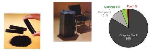
Tens of thousands of small fuel TRISO particles are embedded in a matrix of graphite that provides the structural form of the fuel element (pebbles, cylindrical compacts in hexagonal blocks, plates, etc.). The graphite matrix also conducts heat from the coated particles to the surface of the fuel element. The reactor core designer determines the fuel element geometry and the location of the coated-particle fuel in the graphite. As a result, the fuel element is primarily a matrix graphite and a small amount of carbon in multiple forms is associated with the coated-fuel particles.
There is more than an order of magnitude difference in the volume of used fuel per megawatt-day of energy produced between the different types of fuel. The KP-FHR[Citation4] used fuel volume per unit of energy produced is only two to four times that of light water reactors (LWRs). There are several reasons for this.[Citation20] First, the uranium enrichment is 19.55% 235U and the burnup is near 200 000 MWd per ton versus LWRs with an initial enrichment of 5% 235U and a burnup of 50 000 MWd/ton. Second, in the KP-FHR, the flibe salt provides about half the neutron moderation required for the reactor, reducing the graphite in the core needed for neutron moderation. Last, the reactor core contains graphite pebbles for neutron moderation as well as fuel pebbles.
At the other extreme are the prismatic HTGRs (), where the helium does not provide significant neutron moderation and the graphite used to moderate neutrons in the reactor core is in the fuel assemblies. In all cases, there is a graphite neutron reflector around the reactor core with no fuel. A recent EPRI report[Citation21] provides a recent assessment of graphite volumes for different reactor designs.
III. GRAPHITE ROADMAP
The goal of the carbon roadmap is to map out the options to enable the systematic study of options to determine the most economic method for carbon management within regulatory and safety constraints for any set of goals, be it direct disposal of graphite and used fuel or the recycling of graphite and fissile fuel. shows the top level of the roadmap. The roadmap is applicable to the management of existing irradiated carbon and future carbon.
Fig. 4. Schematic of graphite management options.
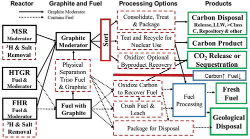
There are several differences in this roadmap relative to much of the earlier work in the literature. First, the expectation that many high-temperature reactors will be built creates the option for recycling some fraction of the irradiated graphite back to the reactors. Work on this option started in the U.S. Department of Energy’s (DOE’s) Deep Burn Program.[Citation21–25] In this context, the different geometries and requirements for graphite components in HTGRs, FHRs, and MSRs create a wide set of potential recycling options, including the pebble bed graphite moderator for the FHR, which is a much simpler geometric form to fabricate when recycling irradiated graphite.
Second, there have been advances in reprocessing[Citation26] that may reduce the cost of reprocessing and simultaneously create new carbon waste forms applicable to both recycling and the management of MSR graphite waste. There has been work on recovering fissile materials by
Grinding the fuel.
Leaching the carbon with nitric acid to remove the fissile materials, with the solution containing fissile materials and soluble fission products then sent to the reprocessing plant.
Consolidating carbon waste that contains noble metal fission products and crushed silicon carbon shells into a new carbon waste form.
Graphite, fission product noble metals, and silicon carbon do not dissolve in nitric acid. This process leaves the carbon in a solid dense form for disposal. The noble metals could have significant economic value if recovered in pure forms.[Citation27,Citation28] Earlier work examined the recovery of noble metals from reprocessing plants. We are not aware of any work on the recovery of noble metals from carbon wastes. There is significant work to indicate that graphite is an excellent waste form.[Citation29] This carbon waste with noble metals is similar to MSR graphite waste, with noble metal plate out on the graphite surface where one could develop a common process to (1) produce the final waste form or (2) develop options for the recovery of some of these noble metals for other purposes. Such waste forms have much in common with the disposal of irradiated graphite and the recycling of clean irradiated graphite.
Third, advancing technologies from other fields have created new disposal options for irradiated carbon that did not practically exist a decade ago. These disposal options have the potential for low cost and superior isolation of carbon waste containing 14C from the environment.
III.A. Fracking
The oil industry has developed fracking for the recovery of natural gas and oil. The well is drilled to depth and then goes horizontal for long distances. The horizontal section follows the local geology, which contains oil and natural gas. Then a mixture of sand and water is injected into the local rock to create fractures. When the pressure is reduced, some of the water bleeds back out of the well and the sand props open the cracks for natural gas or oil to escape from the rock formation. Over time, the cracks disappear. At greater depths, cracks close quickly. The same technology could be used to inject ground graphite solid waste into deep geological formations far deeper and with better waste isolation than a traditional geological repository.
A variant is to inject a cement grout mixture with graphite that solidifies in place. The injection of cement grout deep underground with radionuclides was used at Oak Ridge National Laboratory (ORNL) for intermediate-level waste.[Citation30] This was before the development of horizontal drilling, which enables precise delivery of the grout to the desired underground location. There have been limited assessments of the disposal of volatile fission products, such as krypton, in grout[Citation31] that indicate it is also viable. Since this early work, there has been a revolution in fracking technology in terms of technology and the ability to predict behavior underground.
III.B. Carbon Dioxide Sequestration
With concerns about climate change, there is massive work underway to sequester underground carbon dioxide from fossil fuel, ethanol, and chemical plants[Citation32]; that is, geological disposal of carbon dioxide. Currently, there are more than 200 permit applications being reviewed by the U.S. Environmental Protection Agency. Depending upon the geology, the carbon dioxide may remain carbon dioxide or react with the local geology to form solid carbonate minerals. The same technology can dispose of carbon dioxide containing 14C. The graphite is oxidized, and the carbon dioxide with 14C is injected deep underground.
As discussed in the following, graphite does not “burn” in air and requires special systems for rapid oxidation.[Citation33] While U.S. regulations permit the discharge of oxidized 14C as an effluent as long as the discharges comply with the individual dose protection limits of 10 CFR Part 20, sequestration can enhance safety and reduce the environmental impact of large-scale facilities processing irradiated graphite.
The global scale of any industry ultimately determines the global limits for releases to the environment and would likely apply to 14C. Such sequestration options can be coupled with existing or future carbon dioxide sequestration systems, which would massively dilute the 14C in a much larger volume of carbon dioxide not containing 14C to provide a second layer of protection by isotopic dilution and to reduce the cost of sequestration of the 14C. The health and safety advantage of mixing carbon dioxide from oxidizing irradiated graphite with carbon dioxide from fossil fuel and other sources is that one can immediately dilute the 14C content so that there is no risk of exceeding individual radiation exposure limits now or any time in the future. This is discussed in Sec. V.
We discuss the option space based on by first considering graphite management at the reactor, and then separately nonfuel graphite, and then options for graphite-matrix coated-particle fuel management. There are mechanical and chemical methods to separate carbon in the fuel elements from the coated particle fuel[Citation29]; thus, many fuel-processing options will generate carbon streams to manage using the same methods developed for the graphite moderator.
IV. AT-REACTOR MANAGEMENT OF GRAPHITE AND USED NUCLEAR FUEL
Different strategies are used to manage irradiated graphite and used nuclear fuel (UNF) at the reactor. UNF has additional storage requirements to assure criticality control, decay heat removal, and safeguards. The cost of irradiated graphite management is much less than that for UNF.
The roadmap separates graphite by source. The tritium content of FHR[Citation34] and MSR graphite may be orders of magnitude higher[Citation35] than in HTGR graphite and there will be salt on the MSR and FHR graphite. In the FHR, the tritium may be three orders of magnitude larger than in a HTGR from neutron irradiation of the lithium and beryllium in the salt. MSRs, depending on the salt composition, may also have high tritium concentrations in addition to fission product tritium and other radionuclides present in the fuel salt.
In MSRs, there is also fissile, fertile, and fission products in the salt. The fission products include noble metals that plate out on graphite; thus, this graphite will generate significant gamma rays from the noble metal fission products. Noble metals plate out on the graphite and heat exchangers, exit via the off-gas system, and may be removed by salt purification systems; thus, the fraction of noble metals that plate out on the graphite is a strong function of the design.
Fluoride salt–cooled high-temperature reactor fuel and graphite and MSR graphite may be treated at the reactor to reduce the salt and tritium content. First, there are economic incentives to recover the FHR salt coolant and the MSR salt for reuse. The FHR salt is a mixture of isotopically separated 7Li fluoride and beryllium fluoride, and thus valuable. Similarly, there are economic incentives to remove any MSR residual fuel salt from graphite because it contains valuable fissile material. Second, treatment may significantly reduce storage and transport costs. High tritium loadings require consideration of tritium behavior in storage and transport. Last, frozen fluoride salts at low temperatures in irradiation fields can generate free fluorine, which is a health hazard and is corrosive to structural materials.[Citation36]
Tritium is absorbed into graphite. shows the thermal desorption spectra for hydrogen in graphite. Tritium can be removed by heating the graphite. In pebble bed FHRs, where the graphite moderator and fuel pebbles flow through the reactor core, the pickup of tritium by graphite may be used to remove tritium from the coolant, with recovery of the tritium accomplished by heating the pebbles after they have left the reactor core. FHRs and MSRs require systems to remove tritium from the coolant.
Fig. 5. Thermal desorption spectra for hydrogen in graphite, annotated to highlight hydrogen uptake and desorption parameters.[Citation37–39]
![Fig. 5. Thermal desorption spectra for hydrogen in graphite, annotated to highlight hydrogen uptake and desorption parameters.[Citation37–39]](/cms/asset/9d73dbf9-51da-47c4-959d-5d50654accce/unct_a_2337311_f0005_c.jpg)
It is likely that any graphite material going into storage will be heated above Its normal operating temperature to drive off tritium that is not tightly bound to the carbon. This may include a circulating inert gas to assist with tritium removal. The higher temperatures will also reduce the viscosity and surface tension of the liquid salt, resulting in less liquid residue on the graphite. With the FHR, higher temperatures can also be used to remove the salt. With a MSR, only the more volatile fluoride salt components can be removed.
There are multiple options for removing the salt, including washing with water to dissolve the salt components. Research is underway into how to limit salt uptake and how to remove salt from the graphite surfaces.[Citation38,Citation40,Citation41] In summary, there are three reasons for salt removal at the reactor: (1) removal of the beryllium, which is a toxic material, so the waste is not classified as chemically hazardous (mixed) waste, (2) recovery of the salt, and (3) avoiding radiolysis of the salt, which can generate fluorine.
V. MANAGEMENT OF GRAPHITE (NONFUEL)
Graphite is sorted into categories based on the 14C content and other criteria. If the graphite is considered a waste, some graphite may be considered nonradioactive, and other graphite may be low-activity graphite that can be disposed of as low-level waste, thus reducing the quantities of graphite requiring more expensive disposal options. Similarly, some fraction of the irradiated graphite may be recycled, while the remainder is disposed of as waste. Last, the graphite may be oxidized and converted into carbon dioxide for release into the atmosphere or sequestration underground.
For most irradiated graphite, most radionuclides will be near the surface of the graphite. There will be 14C in all the carbon, with higher concentrations of 14C near surfaces where nitrogen was adsorbed and later converted to 14C. The degree to which any radionuclide migrates into the graphite depends on the chemical species. This creates options using mechanical, thermal, or chemical treatment to separate the graphite into two categories: (1) relatively clean bulk graphite except for 14C and (2) impurities acquired while being irradiated that are near the surface. The viability of such separations will depend on the specific characteristics of the carbon waste stream.
V.A. Graphite Disposal
Graphite by itself is an excellent waste form that is chemically inert in most geologies. It is also the third most dense form of carbon after diamond and londaleite; thus the minimum low-cost volume waste composition. Historically, most graphite products were made from natural graphite that was mined. Its behavior is understood in many different types of geology.[Citation42] With the development of lithium-ion batteries and other uses that require very high-grade graphite, much of the graphite today is manufactured. Nuclear graphite is made by several different methods. It can be disposed of via near-surface land disposal, in greater-than-Class C disposal facilities, or in repositories, depending upon the 14C content and other radionuclides or impurities associated with the graphite. It can also be disposed of by two “new” options: geological disposal as graphite by direct injection underground with or without grout and oxidized with sequestration of the carbon dioxide.
The choice of disposal option depends on (1) the concentration of 14C and other radionuclides in the graphite, (2) the regulatory structure, and (3) the waste form. In some cases, the waste form defines the disposal option. For example, FHRs are low-pressure reactors with relatively lightweight reactor vessels and higher power densities. One maintenance option that is being considered is to replace the reactor vessel with a graphite reflector once or twice during the reactor lifetime versus the removal and replacement of graphite reflectors. This would take much less time and have lower worker exposure. The reactor would be defueled, the salt coolant drained with a possible water wash to recover residual salt, and the vessel filled with a special grout to fix any radionuclides. The total volumes of graphite in the reflector that remain with the vessel would be small relative to the graphite associated with the fuel and graphite pebbles that are replaced during refueling.
Regulatory structures depend on the country. The discussion herein is in the context of the U.S. regulatory structure. Regulatory structures and associated rules have conservative assumptions that are false for some types of waste. Normally, the cost of changing the rules for a specific waste form exceeds any savings in disposal costs. However, if there are large quantities of a specific waste form, it may be worth modifying those rules for that waste form. Irradiated graphite may be one of those cases. Consider shallow land disposal of graphite waste with 14C. There are four exposure pathways to humans from radionuclides in a shallow land disposal facility:
Inhalation of dust digging into the waste or by a resident living on the reclaimed site.
Ingestion of water from a well dug by the reclaimer.
Consumption of food grown in a garden containing contaminated soil.
Direct exposure of workers or residents from gamma radiation.
In the U.S. Nuclear Regulatory Commission system for radioactive waste disposal, the allowable radionuclide concentration limit per unit volume for each radionuclide is the most conservative concentration from the four pathways that results in a fixed dose limit of 500 mrem/year. For 14C, the limiting exposure pathway is the consumption of food grown on the site after the lapse of institutional control. This limit is three orders of magnitude more restrictive than exposures by the other pathways.
The U.S. regulatory structure assumes 14C is in a chemical form that is taken up by plants. This is a reasonable conservative assumption for many 14C wastes from research where 14C is a radioactive tracer incorporated into various organics and used to understand carbon movement in living organisms. It is not generally true for graphite. Refractory forms of graphite remain inert in the environment for long times because most bacteria and other living organisms are not capable of digesting refractory carbon forms. It is not soluble in water. This is the basis for the sequestration of carbon from anaerobic digestion and flash pyrolysis of biomass to produce liquid hydrocarbon fuels with the recycling of soil nutrients and carbon to agricultural and forest soils.[Citation43]
If there are large quantities of irradiated graphite for disposal, it may be worth developing better estimates of 14C uptake into plants from graphite to allow for higher 14C concentrations in graphite going to shallow land disposal sites. The U.S. Nuclear Regulatory Commission has a procedure to accomplish this.[Citation44] It is not known what the allowable disposal limits of 14C would be if they were modified for the characteristics of nuclear-grade graphite.
If the irradiated graphite requires geological disposal because of concentrations of multiple long-lived radionuclides, there are two major sets of options: (1) high-heat repositories and (2) low-heat repositories. Repositories for UNF and high-level waste (HLW) are much more expensive per unit volume than repositories for low-heat waste.[Citation45] For any repository, there are temperature limits to assure long-term repository performance. High temperatures can degrade waste packages and the local geology. To limit temperatures, UNF and HLW are spread out underground in multiple tunnels in the repository so heat can conduct to the earth’s surface. Most of the heat is from the decay of 137Cs and 90Sr. That spacing makes for very expensive repositories per unit volume. This spacing is not required for low-heat waste, including intermediate (transuranic and greater-than-Class C) waste. Most irradiated carbon waste generates very low levels of heat.
Some countries use geological disposal for hazardous chemical waste, including waste that contains toxic heavy metals (arsenic, cadmium, lead, etc.), which remain hazardous forever. That is not required in the United States. The first geological repository that was build was the Herfa-Neurode geological repository in Germany for hazardous industrial wastes. It is located in a salt dome, and has a capacity of 200 000 tons per year. Since opening in the mid-1970s, it has disposed of more than 3.2 million tons of waste.[Citation46] As Herfa-Neurode and other such facilities have demonstrated, geological disposal of lower-heat radioactive waste can be inexpensive if society choses it to be inexpensive.
Several geological repositories for disposal of long-lived, low-heat radioactive wastes have been built or are under construction. The only operating geological repository in the United States is for low-heat, long-lived radioactive wastes, the Waste Isolation Pilot plant in bedded salt in southern New Mexico. It was originally designed to have one section for the disposal of low-heat waste and a second section for the disposal of UNF and HLW. By law, it is now limited to low-heat defense wastes, primarily plutonium-contaminated wastes. Germany, in the next several years, will open the Konrad repository for low-heat waste. It will accept graphite waste.[Citation47,Citation48] The Swedish Final Repository for Reactor Wastes (SFR) facility is located in granite under the Baltic Sea with a special silo disposal that would likely be acceptable for graphite wastes with high 14C concentrations.[Citation49] However, Sweden does not have any significant irradiated graphite waste.
Separate from these technical and economic considerations is the question of how national waste programs are organized. Historically, in the United States, the U.S. government charged a flat fee for the disposal of UNF based on the energy produced. With such a price structure, there was little incentive to reduce waste volumes, including graphite-containing UNF. At the opposite extreme is the Swedish repository program,[Citation49] managed by the Swedish utilities, where there is a commercial incentive to minimize costs. In this context, the choice of geology has a major impact on costs. Repositories in salt have much lower costs than repositories in geologies such as tuff.[Citation50]
V.B. Convert Graphite into a Useful Product
Irradiated graphite can be recycled back to graphite-moderated reactors,[Citation22–25] both in the fuel and as a graphite moderator. Recycling would likely involve grinding the graphite, mixing with binders, firing at high temperatures, and producing new graphite components. It is expected that recycled graphite would be mixed with fresh graphite in most cases.
This is an area of active research. The costs will depend on the impurities in the irradiated graphite, which in turn depend on the radiation levels and chemical impurities. Historically, this has not received much attention because of a lack of a market; very few high-temperature reactors were being built. If large fleets of high-temperature reactors are deployed, it will create a market and incentives to recycle graphite. In this context, high-temperature reactors use different grades of graphite for different purposes. There is not a single graphite product, but multiple products where economics would determine when recycling graphite makes economic sense.
There are potential nonreactor applications for recycled graphite, primarily associated with waste management. In nonreactor applications, there are two relevant graphite properties: the relatively inert chemical characteristics of graphite and its high thermal conductivity. Graphite could be used in waste packages and backfill materials to improve thermal conductivity, and thus reduce peak waste form and waste package temperatures, as is being investigated by the Swiss.
Reducing temperatures reduces the waste form and container corrosion rates. For example, the current Belgium waste package[Citation51] uses sand as a backfill for the void spaces in the UNF assembly. In a second example, bentonite clay has been proposed as a backfill material to minimize water transport near the waste package. However, bentonite clay has a very low thermal conductivity. There are large incentives to use an inert additive to increase the thermal conductivity of the fill and reduce peak temperature, which lowers the corrosion rates of the waste package. In these cases, nonradioactive graphite is being investigated in the laboratory. Recycling irradiated graphite becomes an option if large assured quantities become available.
V.C. Oxidation of Graphite and Disposal of the Carbon Dioxide
Graphite can be oxidized, producing carbon dioxide, which can then be disposed of or released to the atmosphere depending on radionuclide concentrations. Graphite oxidation may be used for multiple purposes. First, it is an option for graphite disposal. Second, for FHRs, it is an option enabling the recovery of any flibe salt embedded in the graphite. Third, for MSRs, it is an option to recover the noble metal fission products for their commercial value. Fourth, with TRISO fuel, it may be used to eliminate the graphite matrix to reduce the UNF volume for direct disposal of the TRISO particles in a geological repository or borehole. Last, with TRISO fuel, it may be the first step to reprocessing the TRISO UNF to recover fissile and fertile materials. With the last two options, one wants to carefully oxidize the matrix carbon so as not to damage the TRISO fuel particles. If one damages a significant number of TRISO particles, the carbon dioxide will contain fission product gases and other fission products that significantly increase the costs of carbon dioxide gas processing.
The potential quantities of graphite imply that the processing facility may produce heat for plant operations or electricity. However, the energy released from this graphite is small compared to the energy released as a nuclear fuel. In the case of a FHR, the energy release from fission is 87 000 times the energy released from burning the graphite.
There is experience in oxidizing nuclear-grade graphite. There was a major effort to develop UNF recycling technologies, including a large experimental program for these fuels, in the early 1970s at ORNL involving graphite oxidation, with hot cell testing of irradiated fuel to determine any differences between processing nonradioactive materials and real UNF. In the first step, the matrix graphite was oxidized with the TRISO fuel particles remaining intact. Graphite was oxidized at high temperatures with oxygen or oxygen and recycled carbon dioxide to control temperatures. With the recycling of carbon dioxide and control of the oxygen content, one can chose oxidation temperatures.[Citation52]
The TRISO fuel particles where then crushed, and a second oxidation step was undertaken to oxidize the buffer carbon inside the TRISO particles. This step also released tritium, iodine, and krypton. The ash was then dissolved in nitric acid to recover the fissile and fertile materials. Limited quantities of unirradiated graphite fuels have been processed by oxidation of the graphite at Idaho National Laboratory[Citation26] and elsewhere to recover the enriched uranium from unirradiated fuel.
Under normal circumstances, nuclear-grade graphite does not burn[Citation53]; there is slow oxidation. Wood and coal burn partly because high temperatures gasify these materials, producing a complex mixture of steam, carbon monoxide, and oxygenated hydrocarbons, which enables rapid combustion reactions with air. The production of graphite by heating to high temperatures removes that hydrogen, and thus the gasification process that enables the combustion of wood and coal. It creates a structure resistant to burning. Graphite is used in some fire extinguishers to put out metal fires.
In the Windscale and Chernobyl nuclear accidents, metal fuel cladding and fuel did burn; the graphite very slowly oxidized. This implies that oxidation of nuclear-grade graphite, as discussed herein, typically requires grinding the carbon to a smaller particle size, using pure oxygen or steam/oxygen mixtures to aid combustion, and special furnaces.
When these fuel processing programs for HTGR fuel began in the 1970s, the regulatory implications of releasing carbon dioxide with 14C as an effluent to the atmosphere were not fully realized. Current U.S. regulations allow for carbon dioxide containing 14C to be released as a gaseous effluent, if the release complies with the individual protection standards of 10 CFR Part 20. The issue is radiation dose to the local population over time. The primary radiation dose is incorporation of 14C into green plants in locally grown foods near the release point before large-scale atmospheric dilution.
Various strategies to avoid this risk have been investigated since the 1970s, including siting facilities far from areas growing food and gaseous releases only at night when plants do not take up carbon dioxide. However, it is generally recognized that large-scale releases of 14C should be avoided. Initial work at ORNL to immobilize the carbon dioxide from reprocessing graphite fuels was to mix the carbon dioxide with calcium hydroxide to produce stable solid calcium carbonate for disposal.
Carbon-14 does not stay in the atmosphere forever. Atmospheric testing of nuclear weapons added a massive pulse of 14C to the atmosphere from neutron interactions with nitrogen in the atmosphere. This is in addition to the constant rate of 14C generated from cosmic ray interactions with the atmosphere. The atmospheric concentration of 14C has decreased to below that before atmospheric weapons testing[Citation54] in less than 70 years. This occurred by two mechanisms. Carbon dioxide was added to the atmosphere via volcanos, the burning of fossil fuels, and the decay of biological materials. It was removed by dissolution into the ocean and reaction with rocks to form carbonates. Second, atmospheric carbon exchanges with carbon in the ocean, plants, and the soil, three massive carbon sinks relative to the quantities of carbon in the atmosphere, in the form of carbon dioxide.
Today there is a new option for the disposal of carbon dioxide with 14C, sequestration of the carbon dioxide underground. Carbon dioxide from irradiated graphite can be (1) directly sequestered underground or (2) mixed with fossil and other carbon dioxides with massive dilution of the 14C before sequestration underground. The health and safety advantages of mixing carbon dioxide from oxidizing irradiated graphite with carbon dioxide from other sources is that the content of the 14C is immediately diluted so that there is no risk of exceeding individual radiation exposure limits now or any time in the future. The economic advantage is that the costs will be lower because of the massive scale of sequestration operations to support decarbonization of the economy.
There are multiple commercial carbon dioxide sequestration sites, and there is the expectation that there will be many more such systems within the next several decades. The current irradiated nuclear graphite inventory is about 250 000 tons,[Citation1] with projections of an additional 500 000 tons[Citation2] by 2060. If oxidized to carbon dioxide, that is less than 3 million tons of carbon dioxide over many decades. The quantities of carbon dioxide from oxidizing graphite would be less than 100 000 tons per year. There are strong reasons to expect that carbon dioxide sequestration from fossil and biological sources in the United States will exceed 100 million tons per year in this decade and may quickly grow globally to billions of tons per year.
There are three types of carbon dioxide sequestration sites:
Conventional sequestration by the injection of gas into geologies with impermeable cap rocks that prevent the carbon dioxide from migrating upward.[Citation32] Much of the carbon dioxide is trapped in small micro traps and is not releasable under any conditions. This is the existing commercial practice.
Sequestration into basaltic and other rocks with rapid conversion of the carbon dioxide into carbonates.[Citation55] In these rocks, the carbon dioxide within months chemically reacts with calcium and magnesium oxides to form carbonates (limestone). Much of Washington, Oregon, and Idaho is covered with basaltic rock. This disposal option is early in the development cycle.
Deep injection as supercritical fluid. If the carbon dioxide is injected deeper than 2000 to 3000 m underground, the carbon dioxide becomes denser than water. The carbon dioxide over time migrates deeper underground.[Citation56] This disposal option is early in the development cycle.
There are large government economic incentives for the sequestration of carbon dioxide in Europe and the United States, with three large near-term markets: natural gas processing, ethanol plants, and hydrogen plants. These three markets assure a large carbon dioxide sequestration industry and a robust option for the disposal of carbon dioxide containing 14C. The cost of carbon capture and sequestration (CCS)[Citation57,Citation58] is primarily in the capture and production of a relatively pure carbon dioxide stream for disposal. Carbon dioxide sequestration is inexpensive, at less than $20/ton of carbon dioxide. The cost of land disposal of graphite is more than 100 times higher. However, it is required to oxidize the graphite, clean up the carbon dioxide to produce a clean carbon dioxide stream for sequestration, and dispose of any residual impurities that were in the graphite.
The cost of CCS is strongly dependent on the source of carbon dioxide. The cost of CCS associated with fossil power plants is high because of the cost of separating dilute carbon dioxide (typically 10% of the gas flow) from the stack gas. However, there are three processes where process chemistry yields a relatively pure carbon dioxide stream. The cost of sequestration of this carbon dioxide is low. The scale of these industries is creating a large-scale carbon dioxide sequestration industry, which creates the option of economic sequestration of carbon dioxide with 14C from irradiated graphite:
Natural gas production. Some natural gas fields produce natural gas with high concentrations of carbon dioxide. The separation process to produce natural gas acceptable for the pipelines and customers also produces a nearly pure carbon dioxide stream for disposal. This has been done in Norway for over a decade because of a tax on carbon dioxide releases.
Fermentation. The fermentation process to produce ethanol yields almost pure carbon dioxide coming off the fermentation tanks. Pipelines are in the permitting process to collect and sequester the carbon dioxide from corn ethanol plants in the Midwest United States. There are other more distributed sources of pure carbon dioxide. Many large sewer plants produce highly concentrated streams of carbon dioxide, which in the future may be sequestered. These are the low-cost options for negative emissions; that is, reducing the carbon dioxide content of the atmosphere.
Hydrogen. The processes to produce hydrogen from natural gas results in most of the waste carbon dioxide exiting the process as relatively pure carbon dioxide. Today the United States produces about 10 million tons of hydrogen for the production of fertilizers, as a chemical feedstock, and for the production of liquid fuels from crude oil. With current U.S. government incentives, many projects are underway to produce low-carbon hydrogen. The largest plant so far announced is for a natural gas–to-hydrogen plant with sequestration of the carbon dioxide by Exxon at their Baytown, Texas site. That single plant will produce a billion cubic feet of hydrogen per day, with sequestration of 98% of the carbon dioxide. In Europe, Air Liquide has announced it is modifying its hydrogen production facilities in the port of Rotterdam for capture and sequestration of the carbon dioxide. The atmospheric carbon dioxide releases for such a plant per unit of hydrogen with appropriate design are similar to hydrogen from wind and solar plants. Wind and solar plants coupled to electrolysis plants to produce hydrogen have a significant embedded carbon dioxide footprint from the manufacturing process.
The demand for hydrogen from natural gas may increase by an order of magnitude within the next several decades. This would push carbon dioxide sequestration rates to billions of tons per year. There is the potential to replace all crude oil with cellulosic liquid hydrocarbon fuels,[Citation6,Citation7,Citation59] with massive heat and hydrogen inputs in the conversion process. Hydrogen is used to remove the oxygen in biomass (40% by weight) and to provide hydrogen to produce gasoline, diesel, and jet fuel. If all the hydrogen were produced from natural gas, the equivalent of a third to half the U.S. production of natural gas would be converted to hydrogen, with the byproduct carbon dioxide sequestered underground. The refinery heat input would be similar to the existing nuclear fleet, and would be primarily from high-temperature reactors; the largest market for reactors that use graphite moderators and coated-particle fuel.
The other large future hydrogen market is the direct conversion of iron ore into iron by direct reduction with hydrogen. The world converts ~2.5 billion tons of iron ore into iron each year using coal in the form of coke. The alternative chemical reducing agent is hydrogen. In the United States, there are large iron mining operations in Minnesota and massive natural gas deposits in neighboring North Dakota that may result in large natural gas–to-hydrogen plants in North Dakota, with the sequestering of carbon dioxide in North Dakota (appropriate geology) and a hydrogen pipeline to northern Minnesota. In both these applications, the technology exists. What is changing are the ground rules for releases of carbon dioxide into the atmosphere.
The previous sources of concentrated carbon dioxide are a consequence of the chemistry of particular processes. In a separate category is the production of concrete by thermal decomposition of limestone into calcium oxide and carbon dioxides, which produces about 8% of global carbon dioxide emissions. Currently, burning fossil fuels produces the required high-temperature heat. Burning hydrogen or electric heat could replace fossil fuels, producing a stack gas of nearly pure carbon dioxide for sequestration. Cement is one of several examples where there are no good replacements, and thus will create a large CCS industry not dependent on specific process chemistry.
The last CCS market is negative emissions, reducing atmospheric carbon dioxide concentrations. Green plants remove carbon dioxide from the atmosphere. If this biomass is burned and the carbon dioxide is captured and sequestered, it reduces atmospheric carbon dioxide. The largest concentrated sources of this carbon dioxide are paper and pulp mills, where about a third of the carbon entering the plant as pulp wood exits as paper and the remaining carbon wastes are burned to produce energy for the process and exit the plant as carbon dioxide.[Citation60] There are many other sources of carbon dioxide from biological sources, including industrial furnaces that burn biomass, sewer plants, and municipal incinerators. It is reasonable to assume there will be no shortage of large-scale carbon dioxide sequestration facilities that could be used to sequester carbon dioxide containing 14C.
There have been only limited assessments of the sequestration of carbon dioxide containing 14C. We are not aware of any studies that have examined a central plant to oxidize graphite with 14C, recover the heat for industrial or power generation, and sequester the carbon dioxide.
VI. MANAGEMENT OF GRAPHITE-BASED UNF
There are multiple options for the management of graphite-based UNF where economics and policy will define the preferred path or pathways. The economic incentives to recover fissile fuel for recycling depend on the characteristics of the UNF, just like the economics of uranium mining depend on the uranium ore grade. If economics is the criteria, some fuel may be processed for fissile fuel recovery while other fuel is disposed of as waste.
VI.A. Oxidize for Direct Disposal or Fissile Fuel Recovery
If the used fuel is a waste, there are two options: (1) direct disposal and (2) a process to separate some fraction of the graphite from the coated-particle fuel to reduce disposal costs of the fuel component by reducing its volume. In some repository environments, the graphite improves the performance of the TRISO UNF as a waste form.[Citation42,Citation61] In addition, there is the potential to reduce safeguards for high-burnup (>150 000 MWd/ton) pebble bed used fuel[Citation62] because of (1) the fissile-fuel isotopics and (2) the dilute fissile content partly created by the graphite matrix. Consequently, there are tradeoffs in separating graphite from the TRISO fuel particles for disposal. Many methods have been investigated for this separation process.[Citation63,Citation64]
If the goal is to reprocess the fuel, then there are large incentives to separate the bulk of the graphite from the TRISO fuel particles. Oxidation of the graphite is the only process that has been tested at the pilot plant scale and used to recover fissile material from unirradiated fuel.
VI.B. Crush and Leach with Fissile Fuel Recovery
The fuel is (1) crushed and (2) leached with nitric acid to recover the fissile and fertile materials. The fuel is either (1) TRISO particles embedded in graphite or (2) TRISO particles separated from the graphite. Inside the TRISO particles is the fuel and the carbon buffer layer between the fuel and the SiC outer layer. The graphite residue is treated as waste. The carbon waste stream will contain the graphite, the SiC shards from the TRISO fuel, and the insoluble noble metal fission products (highly radioactive). The process avoids generating large volumes of off-gas that is expensive to treat. The carbon is in the form of graphite.
This process is a variant of the industrial process used to produce purified graphite for producing products such as carbon gaskets for internal combustion engines from natural graphite. Natural graphite is cheap but contains many impurities. Impurities are removed by acid leaching. The major difference is the commercial graphite purification process uses low-cost sulfuric acid to remove impurities, whereas nitric acid is used in commercial fuel processing operations to minimize final waste volumes. Natural graphite does not contain noble metals or silicon carbon; thus the commercial process produces pure graphite.
The carbon waste stream is heated and compacted to create a carbon monolith containing the SiC and noble metal fission products. It would become a low-heat intermediate waste, likely requiring geological disposal because of the 14C, the longer-lived noble metal fission products, and any residual transuranics. Except for the SiC, the bulk composition of this stream would be somewhat similar to the graphite moderator from MSRs where noble metals from the liquid salt plate out on the graphite. Conventional aqueous reprocessing of LWR SNF produces dissolver residues that do not dissolve in nitric acid; thus, there is a reasonable understanding of what elements will not dissolve in nitric acid. In the United States, this waste is classified as (1) greater-than-Class C waste or (2) remote-handled transuranic waste.
The dissolved fissile materials, fertile materials, and soluble fission products in nitrate form are sent to a conventional reprocessing plant where fissile and fertile materials are recovered and the fission products are converted into a HLW glass, which is sent to the repository.
VI.C. Geological Disposal of UNF
For graphite-matrix coated-particle fuels, there are two direct disposal options: (1) disposal of the entire fuel element be it a pebble or hexagonal block or some other geometry or (2) separation of the graphite from the TRISO fuel particles with geological disposal of the TRISO used fuel. Disposal technologies and economics determine the preferred option. There may not be one option for graphite-based UNFs because of the very different graphite volume–to–TRISO fuel volume ratios of the different fuel types. The economics of borehole disposal are highly sensitive to volume, whereas disposal costs in conventional geological repositories is dependent on the specific geology, be it salt, granite, or clay. This is not a unique question associated with these fuels. There have been many studies and large-scale engineering tests of rod consolidation of LWR fuel assemblies to reduce storage and disposal volumes. Thus far, the economics have favored storage and disposal without consolidation of the fuel pins.
In terms of repository performance,[Citation42,Citation61] the performance of these UNFs is superior to LWR and most other UNFs. This limits incentives for additional processing to improve waste form performance.
VII. CONCLUSIONS
Most high-temperature reactors use graphite moderators and reflectors. The need for high-temperature heat in a low-carbon world may create massive markets for high-temperature reactors. That market change creates large incentives to map out fuel cycle and waste management options for the irradiated graphite and graphite fuels. There have been large research and development programs since the 1970s with different objectives and goals that provides a starting point for mapping out the options. Much work remains to define options that enable (1) better defining the technical tradeoffs and (2) developing the regulatory framework. Advancing technologies and changing goals may change the preferred technical options.
There are changes going forward in time. The deployment of significant numbers of high-temperature reactors creates the option for recycling some fraction of irradiated graphite back to the reactors. Advanced reactor designs, such as the pebble bed FHR, greatly reduce the volume of used fuel per unit of energy produced, and thus the cost of processing or disposing of such fuels.
Separate from the roadmap has been the development of oil field fracking and methods for the geological disposal of carbon dioxide. These technologies developed for other purposes may offer low-cost disposal options for waste containing 14C with superior long-term isolation of 14C. The cost of carbon dioxide sequestration at scale is less than $20/ton, lower than other disposal options. Mixing carbon dioxide from industrial sources to be sequestered with carbon dioxide containing 14C can isotopically dilute the 14C before sequestration to eliminate any risk of exceeding individual radiation exposure limits.
Acknowledgments
We would like to thank the DOE Office of Nuclear Energy that funded this work under project 22-27674, “Reduction, Mitigation and Disposal Strategies for the Graphite Waste of High Temperature Reactors”.
Disclosure Statement
No potential conflict of interest was reported by the author(s).
Additional information
Funding
References
- “Processing of Irradiated Graphite to Meet Acceptance Criteria for Waste Disposal: Results of a Coordinated Research Project,” IAEA-TECDOC-1790, International Atomic Energy Agency (2016); https://www-pub.iaea.org/MTCD/Publications/PDF/TE-1790_web.pdf.
- A. SOWDER, “EPRI: Progress to Date and Future Plans,” presented at the Spring 2018 Advanced Reactor TAG Mtg., March 20, 2018.
- “X-ENERGY,” X-Energy; https://x-energy.com/.
- “ The Future of Nuclear Power,” Kairos Power; https://kairospower.com/.
- C. W. FORSBERG, “Market Basis for Salt-Cooled Reactors: Dispatchable Heat, Hydrogen, and Electricity with Assured Peak Power Capacity,” Nucl. Technol., 206, 11, 1659 (Nov. 2020); http://dx.doi.org/10.1080/00295450.2020.1743628.
- C. W. FORSBERG and B. DALE, “Can a Nuclear-Assisted Biofuels System Enable Liquid Biofuels as the Economic Low-Carbon Replacement for All Liquid Fossil Fuels and Hydrocarbon Feedstocks and Enable Negative Carbon Emissions?,” MIT-NES-TR-023, Massachusetts Institute of Technology (Apr. 2022); http://dx.doi.org/10.2172/2281710.
- C. W. FORSBERG et al., “Replacing Liquid Fossil Fuels and Hydrocarbon Chemical Feedstocks with Liquid Biofuels from Large-Scale Nuclear Biorefineries,” Appl. Energy, 298, 117525 (Sep. 15, 2021); http://dx.doi.org/10.1016/j.apenergy.2021.117225.
- “Energy Flow Charts,” Lawrence Livermore National Laboratory (2020); https://flowcharts.llnl.gov/.
- “Characterization, Treatment and Conditioning of Radioactive Graphite from Decommissioning of Nuclear Reactors,” IAEA-TECDOC-1521, International Atomic Energy Agency (2006); https://www-pub.iaea.org/MTCD/Publications/PDF/te_1521_web.pdf.
- “High Temperature Gas Cooled Reactor Fuels and Materials,” TECDOC-1645, International Atomic Energy Agency (2010); https://www-pub.iaea.org/MTCD/Publications/PDF/TE_1645_CD/PDF/TECDOC_1645.pdf.
- D. BRADBURY and A. WICKHAM, “Graphite Decommissioning: Options for Graphite Treatment, Recycling, or Disposal, Including Discussion of Safety-Related Issues,” Final Report 1013091. Electric Power Research Institute (Mar. 2006); https://www.epri.com/research/products/1013091.
- M. P. METCALFE et al., “EU Carbowaste Project: Development of a Toolbox for Graphite Waste Management,” J. Nucl. Mat., 436, 158 (May 2013); http://dx.doi.org/10.1016/j.jnucmat.2012.11.016.
- International Project on Irradiated Graphite Processing Approaches, International Atomic Energy Agency (in Press).
- A. WAREING et al., “Development of Integrated Waste Management Options for Irradiated Graphite,” Nucl. Eng. Technol., 49, 5, 1010 (2017); http://dx.doi.org/10.1016/j.net.2017.03.001.
- A. WAREING et al., “Final Publishable CARBOWASTE Report,” Deliverable D-0.3.12, European Commission (June 7, 2013); https://cordis.europa.eu/docs/results/211333/final1-cw1306-final-report-f.pdf.
- A. WICKHAM et al., “Updating Irradiated Graphite Disposal: Project ‘GRAPA’ and the International Decommissioning Network,” J. Environ. Radioact., 171, 34 (2017); http://dx.doi.org/10.1016/j.jenvrad.2017.01.022.
- Molten Salt Reactors and Thorium Energy, 2nd ed., T. J. DOLAN et al., Ed., Woodhead Publishing Series in Energy (2024).
- “Advances in High Temperature Gas Cooled Reactor Fuel Technology,” IAEA-TECDOC-CD-1674, International Atomic Energy Agency (2012).
- “Fort Saint Vrain HTGR (Th/U Carbide) Fuel Characteristics for Disposal Criticality Analysis,” DOE/SNF/REP-060, United States Department of Energy Office of Environmental Management (Jan. 2001).
- “Generic FHR Core Model,” Kairos Power; https://kairospower.com/generic-fhr-core-model/.
- D. MALLANTS et al., “Impact of Advanced Reactors on the Back-End Management of the Nuclear Fuel Cycle: Advanced Reactor Fuel Cycle Landscape Study,” 3002023916, Electric Power Research Institute (Dec. 2022).
- L. L. SNEAD et al., “Deep Burn: Development of Transuranic Fuel for High-Temperature Helium-Cooled Reactors—Monthly Highlights,” ORNL/TM-2010/300, Oak Ridge National Laboratory (Oct. 2010); https://www.osti.gov/biblio/1023833/.
- P. J. PAPPANO and T. D. BURCHELL, “A Study of the Annealing Behavior of Neutron Irradiated Graphite,” Carbon, 49, 1, 3 (2011); http://dx.doi.org/10.1016/j.carbon.2010.08.026.
- T. D. BURCHELL and P. J. PAPPANO, “Recycling Irradiated Nuclear Graphite—A Greener Path Forward,” Nucl. Eng. Des., 251, 69 (2012); http://dx.doi.org/10.1016/j.nucengdes.2011.10.068.
- T. BURCHELL and P. PAPPANO, “DOE Deep Burn Program: The Characterization of Grade PCEA Recycle Graphite Pilot Scale Billets,” ORNL/TM-2010/00169, Oak Ridge National Laboratory (Aug. 2010); https://info.ornl.gov/sites/publications/files/Pub25550.pdf.
- G. D. DELCUL et al., “TRISO-Coated Fuel Processing to Support High-Temperature Gas-Cooled Reactors,” ORNL/TM-2002/156, Oak Ridge National Laboratory (Sep. 2002); https://info.ornl.gov/sites/publications/Files/Pub57144.pdf.
- K. NAITO, T. MATSUI, and Y. TANAKA, “Recovery of Noble Metals from Insoluble Residue of Spent Fuel,” J. Nucl. Sci. Technol., 23, 6, 540 (Mar. 15, 2012); https://doi.org/10.1080/18811248.1986.9735017.
- G. A. JENSEN et al., “Recovery of Noble Metals from Fission Products,” Nucl. Technol., 65, 2, 305 (1984); http://dx.doi.org/10.13182/NT84-A33413.
- A. L. LOTTS et al., “Options for Treating High-Temperature Gas-Cooled Reactor Fuel for Repository Disposal,” ORNL/TM-12027, Oak Ridge National Laboratory (Feb. 1992); https://inis.iaea.org/collection/NCLCollectionStore/_Public/23/072/23072033.pdf.
- C. S. HAASE and S. H. ROW, “Status of the Oak Ridge National Laboratory New Hydrofracture Facility: Implications for the Disposal of Liquid Low-Lever Radioactive Wastes by Underground Injection,” CONF-870306-46, Oak Ridge National Laboratory (1987).
- J. H. SHAFFER and J. O. BLOMEKE, “Hydraulic Fracturing as a Method for the Disposal of Volatile Radioactive Wastes,” ORNL/TM-6931, Oak Ridge National Laboratory (Aug. 1979).
- S. KREVOR et al., “Subsurface Carbon Dioxide and Hydrogen Storage for a Sustainable Energy Future,” Nat. Rev. Earth Environ., 4, 102 (Feb. 2023); http://dx.doi.org/10.1038/s43017-022-00376-8.
- A. THEODOSIOU et al., “The Complete Oxidation of Nuclear Graphite Waste via Thermal Treatment: An Alternative to Geological Disposal,” J. Nucl. Mater., 507, 208 (2018); http://dx.doi.org/10.1016/j.jnucmat.2018.05.002.
- C. FORSBERG and P. F. PETERSON, “Spent Nuclear Fuel and Graphite Management for Salt-Cooled Reactors: Storage, Safeguards, and Repository Disposal,” Nucl. Technol., 191, 113 (Aug. 2015); https://doi.org/10.13182/NT14-88.
- L. VERGARI et al., “The Corrosion Effects of Neutron Activation of 2LiF-BeF2 (Flibe),” Nucl. Mater. Energy, 34, 101289 (2022).
- C. W. FORSBERG et al., “Lessons Learned in How to Conduct Irradiated Salt Experiments,” Trans. Am. Nucl. Soc. Annual Mtg., Indianapolis, Indiana, June 11–14, 2023 (2023).
- L. VERGARI and R. O. SCARLAT, “Kinetics and Transport of Hydrogen in Graphite at High Temperature and the Effects of Oxidation, Irradiation and Isotopics,” J. Nucl. Mater., 558, 153142 (2021).
- L. VERGARI and R. O. SCARLAT, “Thermodynamics of Hydrogen in Graphite at High Temperature and the Effects of Oxidation, Irradiation and Isotopics,” J. Nucl. Mater., 552, 152797 (2021); http://dx.doi.org/10.1016/j.jnucmat.2021.152797.
- H. ATSUMI and Y. KONDO, “Retention and Release of Hydrogen Isotopes in Carbon Materials Priorly Charged in Gas Phase,” Fusion Eng. Des., 131, 49 (2018); http://dx.doi.org/10.1016/j.fusengdes.2018.04.039.
- L. VERGARI et al., “Infiltration of Molten Fluoride Salts in Graphite: Phenomenology and Engineering Considerations for Reactor Operations and Waste Disposal,” J. Nucl. Mater., 572, 154058 (2022); http://dx.doi.org/10.1016/j.jnucmat.2022.154058.
- L. VERGARI et al., “Wetting Behavior of Molten Salts on Graphite,” ANS Student Conf. (2023).
- D. SASSANI and F. GELBARD, “Performance Assessment Model for Degradation of Tristructural Isotopic (TRISO) Coated Particle Spent Fuel,” SAND2019-1906c, Sandia National Laboratory (2019); https://www.osti.gov/servlets/purl/1602111.
- Carbon Science for Carbon Markets: Emerging Opportunities in Iowa, M. L. SCHULTE and J. JORDAHL, Eds., Iowa State University (2022).
- “61.58 Alternative Requirements for Waste Classification and Characteristics,” 10 CFR 61.58. Section 61.58 Alternative Requirements for Waste Classification and Characteristics, U.S. Nuclear Regulatory Commission.
- C. FORSBERG, “Rethinking High-Level Waste Disposal: Separate Disposal of High-Heat Radionuclides (90Sr and 137Cs),” Nucl. Technol., 131, 2, 252 (Aug. 2000); http://dx.doi.org/10.13182/NT00-A3115.
- “Underground Landfill Herfa-Neurode,” Wikipedia; https://de.wikipedia.org/wiki/Untertagedeponie_Herfa-Neurode.
- L. KUHNE, “Lokalisation, Freisetzung, Speziesbestimmung von C-14 und H-3 in Reaktorgraphit,” PhD Thesis, Rheinisch-Westfalischen Technischen Hochschule Aachen, Faculty of Georesources and Materials Engineering (July 6, 2017); PromotionsarbeitLenaKuhneDank(rwth-aachen.de).
- P. BRENNECKE, “Anforderungen an Endzulagernde Radioaktive Abfalle,” Endlager Konrad (Dec. 2014).
- “ Managing the Swedish Nuclear Waste,” SKB (2023); https://www.skb.com/.
- J. CONCA, “Comparing Costs for Deep Geological Nuclear Waste Disposal,” Nuclear News (May 2022).
- “Waste Package Library, A Report of the Radioactive Waste Repository Metadata Management (REPMET) Initiative,” NEA/RWM/R(2019)3, Nuclear Energy Agency (Nov. 4, 2021).
- A. THEODOSIOU, A. N. JONES, and B. J. MARSDEN, “Thermal Oxidation of Nuclear Graphite: A Large Scale Waste Treatment Option,” PLoS One, 12, e0182860 (Aug. 9, 2017); http://dx.doi.org/10.1371/journal.pone.0182860.
- W. WINDES et al., “Role of Nuclear Grade Graphite in Controlling Oxidation in Modular HTGRs,” INL/EXT-14-31720, Idaho National Laboratory (Nov. 2014).
- N. JONES, “Carbon Dating Hampered by Rising Fossil-Fuel Emissions,” Nature (July 7, 2022); https://www.nature.com/articles/d41586-022-02057-4.
- S. O. SNAEBJORNSDOTTIR et al., “Carbon Dioxide Storage Through Mineral Carbonation,” Nat. Rev. Earth Environ., 1, 90 (Jan. 2020); https://www.nature.com/articles/s43017-019-0011-8.
- F. PARISIO and V. VILARRASA, “Sinking CO2 in Supercritical Reservoirs,” Geophys. Res. Lett., 47, e2020GL090456 (2020); http://dx.doi.org/10.1029/2020GL090456.
- E. S. RUBIN, J. E. DAVISON, and H. HERZOG, “The Cost of CO2 Capture and Storage,” Int. J. Greenhouse Gas Control, 40, 378 (2015); http://dx.doi.org/10.1016/j.ijggc.2015.05.018.
- W. J. SCHMELZ, G. HOCHMAN, and K. G. MILLER, “Total Cost of Carbon Capture and Storage Implemented at a Regional Scale: Northeastern and Midwestern United States,” Interface Focus, 10, 20190065 (2020); http://dx.doi.org/10.1098/rsfs.2019.0065.
- C. W. FORSBERG, “What is the Long-Term Demand for Liquid Hydrocarbon Fuels and Feedstocks?,” Appl. Energy, 341, 121104 (July 1, 2023); http://dx.doi.org/10.1016/j.apenergy.2023.121104.
- W. J. SAGUES et al., “Prospects for Bioenergy with Carbon Capture & Storage in the United States Pulp and Paper Industry,” Energy Environ. Sci., 13, 2243 (2020); http://dx.doi.org/10.1039/D0EE01107J.
- B. P. VAN DEN AKKER and J. AHN, “Performance Assessment for Geological Disposal of Graphite Waste Containing TRISO Particles,” Nucl. Technol., 181, 3, 408 (2013); http://dx.doi.org/10.13182/NT11-103.
- C. FORSBERG and A. KADAK, “Safeguards and Security for High-Burnup TRISO Pebble-Bed Spent Fuel and Reactors,” Nucl. Technol., 210, 1354 (2024); http://dx.doi.org/10.1080/00295450.2023.2298157.
- A. J. MCWILLIAMS, “High Temperature Gas-cooled Reactor (HTGR) Graphite Pebble Fuel: Review of Technologies for Reprocessing,” SRNL-RP-2015-00744, Savannah River National Laboratory (Sep. 2015); http://dx.doi.org/10.2172/1214176.
- S. T. ARM et al., “Plan for Developing TRISO Fuel Processing Technology,” PNNL-32969, Pacific Northwest National Laboratory (June 2022); https://www.pnnl.gov/main/publications/external/technical_reports/PNNL-32969.pdf.