
 ?Mathematical formulae have been encoded as MathML and are displayed in this HTML version using MathJax in order to improve their display. Uncheck the box to turn MathJax off. This feature requires Javascript. Click on a formula to zoom.
Abstract
The restart of the Transient Reactor Test facility (TREAT) will once again provide the capability for rapid transient testing of fuel concepts. Under the auspices of the U.S. Department of Energy’s Office of Material Management and Minimization, research is underway to assess the feasibility of converting the current high-enriched uranium (HEU) fuel in TREAT to low-enriched uranium (LEU) fuel. The LEU concept retains the fuel process that results in micrometer-sized UO2 fuel grains dispersed in a graphite moderator matrix. The LEU fuel design includes more 238U, which fundamentally changes the feedback mechanisms in the fuel. To explore the effects of conversion on a pulse transient, a simplified semi-infinite TREAT fuel element model of both the HEU and proposed LEU configurations was simulated using MAMMOTH with the requisite multiscale and multiphysics coupling. The developed method incorporates fission energy deposition at microscale locations from the Mesoscale Atomistic Glue Program for Integrated Execution (Magpie), heterogeneity effects from the microscale model in the form of time lag, and independent feedback temperature sources from the microscale fuel grain model and surrounding moderator. The fuel grain size was varied along with temperature feedback sources to explore the feedback mechanisms. Significant differences between fuel and graphite temperatures were found to develop for transients with large energy depositions, for large fuel grains, and for fission-fragment irradiated graphite. These differences in temperature do not influence the feedback for HEU fuel but have a significant effect on LEU fuel. The difference between HEU and LEU fuel is caused by the fuel temperature feedback coefficient for LEU fuel that is roughly 20% of the graphite temperature feedback coefficient. The immediate equilibrium assumption is invalid for LEU fuel in certain TREAT operating regimes. As the conversion of TREAT to LEU fuel aims to conserve HEU capabilities, MAMMOTH simulations of the LEU model explore the effects of matching the same period, peak power density, and deposited energy of the HEU model. The same pulse shape was not achievable due to the feedback mechanism changes.
I. INTRODUCTION
Idaho National Laboratory (INL) has recently restarted the Transient Reactor Test facilityCitation1 (TREAT). TREAT’s purpose is the testing of nuclear fuel concepts under severe accident conditions to assess their resilience against failure. Within the U.S. Department of Energy’s research portfolio, TREAT provides the unique ability to test reactor material concepts during simulated reactor transient conditions.Citation2
TREAT is a graphite-moderated thermal reactor. The fuel consists of UO2 fuel grains suspended in a graphite moderator matrix with grain sizes on the order of μm (CitationRef. 3). Currently, high-enriched uranium (HEU) fuel at 93.24 wt% 235U is used within the core.Citation4 The 121.92-cm active fuel region within a fuel element is clad by Zircaloy-3, with 60.96-cm-tall aluminum-clad graphite regions above and below the fuel region. Within the core, fuel elements have a pitch of 10.16 cm; each fuel element is an octagonal prism of graphite with a distance across the flats of 9.804 cm enclosed in Zircaloy canning of thickness 0.13 cm; the octagon’s short edge at each corner has a length of 1.59 cm. The reactor cavity is designed to house up to 361 assemblies in a
rectangular lattice. The overall dimensions of the TREAT core region are
cm, which is surrounded by a graphite reflector and a concrete biological shield. TREAT is a dry reactor using graphite-moderated fuel and forced air coolant.
TREAT may produce varying transient power profiles including a self-limiting pulse transient. Self-limiting pulse transients rely on the reactor having a negative temperature feedback coefficient; as the TREAT reactor increases in power, the reactor temperature increases, causing the core reactivity to be reduced. A self-limiting pulse is triggered by an initial withdrawal of control rods inserting positive reactivity, which increases the reactor power. The power increases until the negative feedback caused by the increase in temperature balances the initial reactivity insertion.
The current effort to convert TREAT to a low-enriched uranium (LEU) fuel has maintained a fuel concept similar to that of the current HEU fuel. The LEU fuel design also consists of fuel grains suspended in graphite, but the ratio of moderator to fuel masses is different from the HEU ratio.Citation5 The different fuel isotopics change the relevant feedback mechanisms that control the transient pulse. While the spectral shift is the only relevant feedback mechanism in the HEU case, both the spectral shift in the fuel and Doppler broadening in 238U resonances in the UO2 fuel grains play an important role for an LEU-fueled core.
In this paper, two multiphysics, multiscale models of a simplified TREAT fuel element are introduced: the original HEU configuration and the proposed LEU configuration. These models take into account both relevant feedback mechanisms by explicitly computing separate fuel grain and graphite temperatures for interpolating fuel grain and graphite cross sections, respectively. The multiscale nature of the problem arises from the distribution of microscopic fuel grains in the graphite matrix. The fuel grain temperatures over the transient may differ significantly from the temperature of the surrounding graphite.Citation6,Citation7
The microscopic size of the fuel grains makes it impossible to resolve the temperature variations on any reasonable mesh used for the transient neutronics analysis. However, separation of the two prevalent length scales resolves this challenge. The neutronics analysis is performed on a mesh characterized by centimeter-sized elements, while grain treatment is on the micrometer element scale where heat conduction problems are solved on microscopic domains encompassing a single fuel grain and the proportional amount of graphite. Two temperature fields, graphite and fuel grain average temperatures, are obtained from the set of microscopic solutions.
From the energy released in fission events, roughly 80% is carried away by heavy fission products. These fission products have ranges on the same order as the fuel grain size, roughly tens of micrometers. Hence, the shape of the effective heat source for the microscopic heat conduction problem is not identical to the shape of the fission density, which is essentially constant across the fuel grain and zero in the graphite, but features a more complicated spatial distribution that is largest in the fuel grain but nonzero in the graphite close to the grain-graphite interface. The phenomenon of redistribution of the heat source due to ballistic transport of fission fragments is termed ballistic energy transport in this work. Binary-collision Monte-Carlo (BCMC) simulations, outlined in CitationRef. 6, are used to determine the shape of the heat source for the microscopic heat conduction problem.
The novelty of this work lies in the combination of a transient neutronics analysis of TREAT with feedback driven by a multiscale analysis of the fuel and graphite temperature fields. While CitationRef. 3 provides microscale analysis of fuel and graphite temperatures, preexisting reactor power traces provide the magnitude of the time-dependent heat source. In contrast, this work solves a fully coupled problem where multiscale analysis of fuel and graphite temperatures predicts core power as a function of time.
I.A. Governing Physics
Because of the TREAT restart program and resumption of transient testing,Citation8 new simulation tools, not available previously, are being applied to modeling TREAT experiments. At the forefront of the these tools is the MAMMOTH reactor physics application,Citation9–Citation13 which is based on the Rattlesnake multiphysics radiation transport code.Citation14
Proper simulation of the feedback mechanisms of TREAT requires coupling the transient neutron transport equation with the heat conduction equation. In lieu of the more complicated neutron transport equation, the neutron diffusion equation with homogenization equivalenceCitation15 models the neutron population in the reactor. The transient, multigroup neutron diffusion equation along with neutron precursor equations is given by
and
where
| subscripts | = | energy group and delayed neutron group, respectively |
| = | spatial coordinate and temperature dependency | |
| = | neutron speed | |
| = | neutron scalar flux | |
| = | neutron diffusion coefficient | |
| = | macroscopic removal cross section | |
| = | macroscopic scattering cross section from group | |
| = | probability of a neutron being born in energy group | |
| = | fraction of delayed neutrons | |
| = | eigenvalue of the initial criticality calculation | |
| = | fission neutron production cross section in group | |
| = | decay constant of the delayed neutron precursors in group | |
| = | delayed neutron precursor concentration in delay group | |
| = | temperature distribution. |
The heat conduction equation is given by
where
| = | density | |
| = | specific heat capacity | |
| = | thermal conductivity | |
| = | volumetric heat source stemming from fission reactions. |
The transient neutron diffusion equation, Eq. (1), and the heat conduction equation, Eq. (2), are coupled by the temperature dependence of the nuclear cross sections and the fission distribution determining . The MAMMOTH reactor multiphysics application solves Eqs. (1) and (2) simultaneously.
Temperature feedback to the neutron diffusion equation is rendered by the temperature dependence of the nuclear cross sections. First, spectral shift is introduced, which is the the only relevant feedback mechanism in the HEU TREAT configuration. plots the energy dependence of three relevant microscopic cross sections for thermal and epithermal energies.Citation16 TREAT is a thermal reactor, so the majority of fission reactions are caused by thermal neutrons. In the thermal range, the neutron spectrum is roughly shaped like a Maxwellian (neglecting thermal leakage and absorption) whose average energy is largely determined by the graphite scattering properties. At higher graphite temperatures, the graphite scattering kernel preferentially upscatters neutrons to higher energies, which in effect shifts the Maxwellian to higher neutron energies. This moves a significant number of neutrons into energy regions where the fission cross section is lower. With less probability for fission, events removing neutrons, such as absorption and leakage, increase. These two factors (decreased fission and increased removal of neutrons) reduce the reactivity of the reactor.
Fig. 1. Three important microscopic cross sections influencing temperature feedback in both HEU and LEU TREAT fuel.
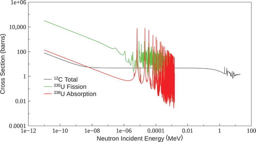
The average temperature of the graphite around a fuel grain parameterizes the Maxwellian distribution of neutrons in thermal equilibrium because virtually all collisions that eventually leave the neutron in thermal equilibrium occur in the graphite moderator. Consequently, for the feedback effect of spectral shift, the temperature in the fuel grain is virtually irrelevant.
Conversion to LEU TREAT fuel changes the abundance of 238U significantly. In contrast to 235U, 238U features capture resonances that broaden as the fuel temperatures rises, leading to an increase in resonance absorption; this feedback mechanism is referred to as Doppler broadening.Citation17 Similar to spectral shift, Doppler broadening reduces the reactivity as the temperature increases, but it depends on the temperature in the fuel grain and not on the temperature in the graphite. For the LEU TREAT reactor, both spectral shift and Doppler broadening are relevant feedback mechanisms.
I.B. Multiscale Problem
The TREAT fuel design consists of UO2 grains, approximated as spherical particles, with an average radius of approximately 10 μm (CitationRef. 18) dispersed in a vast amount of graphite. The fuel grains give rise to a second length scale in addition to the length scale set by the mean free path of neutrons, which is on the order of centimeters in TREAT HEU fuel. The fuel grain length scale will be identified as the microscale within this work. The microscale arises from the shape of the volumetric heat source that consists of a small background and tall, narrow peaks centered around fuel particles. Accordingly, the temperature field
has features with characteristic length scales on the order of about 10 μm. In contrast to the temperature, the neutron flux varies smoothly over length scales roughly comparable to 1 mean free path, which is of the order of 10 cm. Neutronically, the heterogeneity of the fuel does not affect the neutron flux because the mean free path is much larger than the size of the fuel grains, even in the thermal range and at strong resonance energies. provides typical fuel grain mean-free-path values.
TABLE I Illustrative Fuel Grain Mean Free Paths
For spectral shift effects, the microscale heterogeneity separates the bulk of the heat source, i.e., the fuel grain, from the feedback controlling material, i.e., the graphite moderator. The energy from fission deposited in the fuel grain as heat must diffuse to the moderator in order to raise its temperature; the rate of diffusion is controlled by the thermal diffusivity. This phenomenon is termed “time lag.”Citation19 In the LEU configuration, the elevated temperature in the fuel grain leads to an immediate Doppler feedback. Consequently, for a faithful representation of TREAT’s feedback behavior, the microscale features of the temperature may need to be resolved because the immediate equilibrium assumption, i.e., that graphite and fuel exhibit the same temperature, could be invalid leading to inaccurate predictions for LEU fuel.
The current work focuses on examining both HEU and LEU TREAT fuel in a simple fuel element proposing a new method that explicitly accounts for the relevant feedback mechanisms and improves the heat source description. Coupling the neutron diffusion equation to the heat equation removes the need to specify a prescribed power profile. Instead, initial conditions are set, and then, reactivity is inserted to start the pulse. From this point on in the simulation, the coupled equations interact without further “external” changes. The weighted sum of the neutron fluxes from the simulation solution is proportional to the power density used in the heat equation. The temperature solution adjusts the temperature-dependent cross sections used in the neutron diffusion equation. The Mesoscale Atomistic Glue Program for Integrated ExecutionCitation6 (Magpie) performs BCMC calculations informing the heat source distribution to include energy deposited in the graphite from fission fragments originating in the fuel grain’s outer region. Both HEU and LEU TREAT assemblies are modeled using MAMMOTH.
II. METHOD DESCRIPTION
A faithful representation of the relevant physics for the LEU TREAT core may have to account for the multiscale aspect of the problem, the reactivity feedback resulting from the computed temperature distribution, and possibly a realistic representation of the heat source. This section contains the description of the multiscale time-lag coupling approach and the BCMC method informing the heat source. The developed MAMMOTH model combines all the processes for modeling both HEU and LEU TREAT fuel elements during a self-limiting transient pulse.
II.A. The Multiscale Model
A physically valid representation of the time lag may require resolving the temperature field on the scale of the fuel grains, i.e., micrometers. However, because of limitations in computational resources, any reasonable mesh used to discretize the neutron diffusion equation is limited to mesh spacings on the order of several centimeters. Hence, the microscale features of the temperature distribution cannot be represented on the neutronics mesh.
Therefore, a multiscale approach is proposed solving the neutron diffusion equation, Eq. (1), on an underresolved mesh dictated by the neutron mean free path. At a sufficient number of points in the neutronics domain, microscale heat conduction calculations are performed. Each microsimulation consists of a one-dimensional spherical mesh of a fuel grain, approximated as a sphere, surrounded by a spherical shell of graphite moderator. The outer radius of the graphite shell varies with the fuel radius to keep the fuel-to-graphite volume constant; the exact fuel grain size and shape are unknown for HEU fuel due to uncertainty introduced during manufacturing.
From the neutron diffusion solution, the local power density is computed by
where is the fission heating cross section in group
. The number of fission events in the fuel grain at
per unit volume of fuel and time is
where is the energy released per fission event and
is the ratio of fuel volume to moderator volume. As the mean free path of thermal neutrons is much larger than the radius of the fuel grains, the fission density in the fuel grains may be assumed to be uniform. However, the volumetric heat source
is not uniformly distributed as fission energy is released in the form of kinetic energy provided to heavy fission fragments, electrons, neutrons, and photons. While the mean free path of electrons, neutrons, and photons is much larger than the size of the fuel grains, heavy fission fragments exhibit mean free paths on the order of micrometers. Consequently, the volumetric heat source consists of two parts: first, the heat deposited by heavy fission fragments with a shape that is governed by the transport of heavy ions and secondary knock-on atoms in the fuel grain and graphite matrix and second, a uniform background stemming from the long-range fission products. The heat source is given by
where
| = | rate of energy deposition per unit volume at position | |
| = | fission rate density | |
| = | fraction of fission energy that is imparted in long-range fission products, |
The computation of will be discussed in more detail in Sec. IV.
At each location , the fuel and graphite moderator temperature distributions,
from Eq. (2), are computed while applying a no-heat-flux boundary condition on the outer edge of the graphite shell. The average fuel and graphite temperature fields
and
, respectively, are computed from the microstructure solution as
and
where is the volume of the fuel grain and
is the volume of the graphite moderator shell. From the collection of fuel and graphite temperatures
and
, two temperature fields
and
are interpolated, respectively:
and
where denotes interpolation defined by the values
at the points
. For convenience, the difference between fuel grain and graphite temperatures is denoted by
in the remainder of this work.
As pointed out previously, temperature feedback to the neutron diffusion equation is rendered by the temperature dependence of the cross sections. The centerpiece of this work is to use the two temperature fields, and
, separately to interpolate fuel grain and graphite moderator cross sections to subsequently be homogenized. The homogenized macroscopic cross section
of arbitrary reaction type is computed by
where and
are the macroscopic cross sections of the fuel grain and moderator, respectively, and
and
are the average scalar fluxes in the fuel grain and moderator, respectively. As the fuel grains are effectively transparent even for neutrons of resonant or thermal energies,Citation20
such that Eq. (8) simplifies to the volume weighted average as
The traditional approach for modeling of TREAT feedback uses the immediate equilibrium assumption, where cross sections are evaluated at the reactor temperature that is obtained by assuming adiabatic heat deposition implying
.
II.B. Volumetric Heat Source Calculation Using BCMC
The energy deposition rate density of heavy fission products is governed by the transport and stopping of heavy ions and secondary knock-on atoms in the fuel grain and graphite matrix. The range of heavy fission fragments is comparable to the size of the fuel grain, and hence, fission events occurring at the outer rim of the fuel grain deposit some of their energy in the surrounding graphite.
In order to elucidate the shape of , the MyTRIM BCMC codeCitation21 is used. MyTRIM is an extension of the SRIM code to multidimensional geometries and is coupled to the Multi-physics Object Oriented Simulation EnvironmentCitation22 (MOOSE) through the Magpie application allowing Monte Carlo applications to be integrated with finite element simulations. MyTRIM implements the capability of tracking heavy ions created by fission and follow-on atoms that are knocked from their lattice positions in the ensuing radiation damage cascade. The energy deposition of these knock-on ions is tallied on the finite element mesh to compute
. The shape of the heat energy deposition rate density
does not change significantly with the magnitude of
; consequently, precomputing
and then scaling as needed comprise a viable approach. Magpie computes
by sampling heavy fission fragments’ starting locations in the fuel grain, then calling the MyTRIM module to form the displacement cascade, and finally tallying the energy deposition on the spherically symmetric, uniform finite element method mesh. The details of the sampling process of primary heavy fission products are explained in detail in CitationRef. 6.
The results of the BCMC calculations show that depends on the fuel grain’s radius but is insensitive to the type of fuel, HEU or LEU fuel in this work. Comparing the HEU and LEU fuel compositions, the respective
was found to be visually indistinguishable with maximum relative differences around 0.1%. For fuel radii 5, 10, and 20 μm,
is plotted in . For each grain radius, the tallied energy deposition rates are fitted with two separate polynomials, one within the grain and one outside of it. Within the grain an even polynomial of order four is used to maintain symmetry at
, while in the graphite a polynomial of order three is used. At the grain radius
, continuity is not enforced, which allows more accurate fits in the bulk material and does not negatively affect the heat conduction calculations. For
, the heat deposition is set equal to
because the value is very small causing the polynomial fit to oscillate around zero and exhibit small, but negative,
.
III. PROBLEM DESCRIPTION
This work constitutes a proof of principle demonstrating that the proposed modeling approach for a potential TREAT LEU core is viable. To this end, a simplified problem geometry is provided, namely, a single TREAT fuel element without air channels and cladding. Reflective boundaries are applied on the left, right, front, and back boundaries (), while the top and bottom of the fueled portion of the fuel element are covered by a graphite reflector with vacuum boundary conditions. lists the characteristics of the fuel element model and the neutronics mesh.
TABLE II Macroscale Mesh Characteristics
Four equidistant locations on the x-y plane 2.413 cm from the -z and
-z edge of the simplified fuel element are spaced every 10.997 cm in the z-direction in the fuel starting 5.498 cm from the graphite reflector. Thus, 44 locations within the fueled region of the fuel element are selected as sites for the microsimulations. The power density, calculated from the sampled flux at each location, is transferred to a single microscale simulation. provides the dimensions for the microscale unit cells. A transition region next to the fuel grain in the moderator shell features mesh elements of a different size than found in the rest of the moderator shell. The microscale volume ratio of moderator to fuel grain is 2572 and 626 for the HEU and LEU configurations, respectively.
TABLE III Microscale Spherical Unit-Cell Characteristics
The MOOSE MultiApp systemCitation23 handles the multiscale and information transfer needs of the proposed method. To supply the macrosimulation with the informed feedback temperature, the average temperature value of the graphite, the fuel grain, or both are transferred to the macrodomain from each microsimulation.
III.A. Temperature-Dependent Cross-Section Generation
The two-temperature-dependent cross-section library requires the computation of separate cross sections for the fuel and graphite because cross-section mixing is delayed until after interpolation at the respective fuel and graphite temperatures. The microscale geometry for the 20-μm-radius fuel particle is supplied to Serpent 2 (CitationRef. 24) for generating the cross-section libraries for both the HEU and the LEU configurations. The ENDF/B-VII.1 dataCitation16 is used by Serpent 2 to collapse the cross sections to 11 energy groups for material temperature combinations from 300K to 1000K in 100K increments. The partial graphitization of the TREAT fuelCitation4 is considered when creating the cross-section libraries. The carbon is separated into graphitized carbon, taking into account the scattering, and free-gas carbon.
The Serpent 2 model consists of a three-dimensional array of cubic unit cells. Each unit cell comprises a fuel particle in the center with an amount of graphite surrounding it commensurate with the graphite volume ratio of the HEU or LEU fuel ratio. The Serpent 2 domain consists of 20 unit cells in each direction forming a cube comprising 8000 unit cells. The number of unit cells is chosen to optimize tally statistics. Reflective boundary conditions are applied at the outer surface of the Serpent 2 domain. Ten batches of 1 million histories each are used to establish the correct neutron source distribution, and the results of 100 histories each with a population of 1 million neutrons contribute to the tallied quantities: the eigenvalue and the neutron flux for collapsing cross sections to the 11-energy-group set of cross sections. lists the boundaries between energy groups.
TABLE IV Upper Energy Group Boundaries of the 11-Group Structure*
Cross sections for HEU and LEU fuel are prepared using the atomic densities provided in and , respectively, at combinations of graphite and fuel temperatures that are spaced K apart. Linear interpolation provides cross-section values between tabulated Serpent 2 values. Boron dilution in the moderator serves as the mechanism to insert the reactivity that starts the transient. The boron concentrations are varied between the rod-in state and the rod-out state. The rod-out state is the nominal amount of boron found in the TREAT fuel, while the rod-in state on the opposite end of the spectrum is chosen to be sufficiently large for the purpose of this work. Insertion of reactivity starts from the initial boron concentration at
and is then linearly reduced to the rod-out boron concentration at time
; for
the boron concentration stays constant. The increased rod-in boron concentration removes thermal neutrons from the neutron spectrum. Moving to the reduced rod-out boron concentration effectively increases the number of thermal neutrons available for fission reactions starting the transient. The value of the initial boron concentration is adjusted for different cases to match the desired reactor period.
TABLE V HEU TREAT Fuel Atomic Density Values (×1024/cm3)*
Dilution of boron between the rod-in state and rod-out state removes neutron absorbing material much the same way the movement of control rods actually removes neutron absorbing material in the TREAT reactor. Control rods are not explicitly modeled in this work, but extension of the presented method to models including control rods is straightforward.
III.B. MAMMOTH Simulation
The MOOSE-based reactor multiphysics code MAMMOTH is used for implementing the proposed model. Using the MOOSE MultiApp system, MAMMOTH provides the capability to simultaneously solve the neutronics equations along with an arbitrary number of microscale heat conduction problems. The information transfer between the different scales is facilitated by MultiApp transfers that are a native functionality of MOOSE. Point values of the power are transferred to the heat conduction problems, while average graphite and fuel grain temperatures are transferred from the microscale and subsequently interpolated to obtain the corresponding feedback temperature fields.
To ensure iterative convergence of the multiscale problem, a tightly coupled scheme is deployed at each time step solving the neutronics problem and the heat conduction problems sequentially but iterating until mutual compatibility of the power density and the graphite and fuel grain temperatures is achieved. A backward Euler scheme is applied to discretize the time derivatives for both the neutronics and heat conduction problems. First-order Lagrange shape functions are used for the spatial discretization of the partial differential equations.
Material properties appearing in the heat conduction equation, i.e., the heat conduction coefficient, specific capacity, and density, are taken from CitationRef. 3. Within this work, the effect of fast neutron radiation damage on the heat conduction coefficient is not considered; i.e., equations without damage effects from CitationRef. 25 are used, namely, Eqs. (1) and (2) for the thermal conductivity and specific heat capacity of the fuel, respectively, and Eq. (3) for the heat capacity of graphite. The density and thermal conductivity of graphite are set to the constant values suggested in CitationRef. 3.
IV. RESULTS
The developed feedback model is used to investigate the performance of HEU and LEU TREAT fuel within a parameter space that is typical for TREAT operation. Before deploying the feedback model, a demonstration that significant temperature differences between fuel and graphite occur for sufficiently high-powered transient trajectories, for large fuel grains, and fission fragment irradiated fuel is presented; significant differences between HEU and LEU fuel are found and explained. These findings motivate the investigation of the effect of on the feedback of HEU and LEU fuel. Finally, the results of evaluating the performance of HEU and LEU TREAT fuel are presented.
IV.A. Temperature Difference Between Fuel and Graphite During Typical TREAT Transients
The motivation for the proposed feedback model rests on the contingency that significant temperature differences between the fuel and graphite may occur during TREAT transients executed within the normal operating envelope of the TREAT reactor.
The magnitude of for a range of parameters typical for TREAT fuel and operations is investigated using prescribed power density profiles of the EOS and E4 pulses taken from CitationRef. 3. This part of the study solves only a heat conduction problem comprising a fuel grain and the allotted graphite; the computed temperatures provide no feedback to the evolution of the power. Therefore, the only difference between HEU and LEU fuel is the ratio of fuel to graphite volume. The EOS pulse is a short and strong pulse with a peak power of
MW and a duration of
s, while the E4 pulse is significantly longer and weaker with a peak power of
MW and a duration of
s. During the EOS pulse about three times as much energy is deposited into the reactor as for the E4 pulse. Two fuel grain radii
μm and R = 20 μm as well as fresh and irradiated fuel are considered. Following CitationRef. 3, fresh fuel uses the thermal conductivity of
everywhere in the graphite, while irradiated fuel has a reduced thermal conductivity of
in the 15-μm-thick graphite layer just outside the fuel particle. The parameters selected are realistic for TREAT operation, and consequently, the observed
is realistic within the provided parameter space.
A secondary objective is to assess how important ballistic transport of heat via fission fragments is for the thermal behavior of TREAT fuel grains. The importance of ballistic transport is studied by comparing simulations where the contribution from fission fragments to the heating rate density is assumed to be uniform across the fuel grain and zero in the graphite with the BCMC-informed heat source described in Sec. II.B.
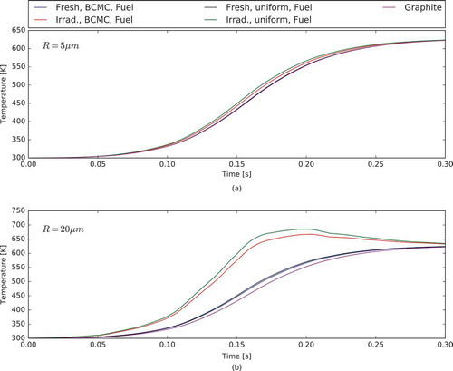
For the HEU fuel configuration, the computed fuel grain and graphite temperatures for the EOS and E4 pulses are depicted in and , respectively. While the fuel temperature changes significantly across the parameter space—fuel grain radius, inclusion of ballistic energy transport, and irradiation condition of the graphite—the graphite temperature depends only on the strength of the pulse. The trajectories of the fuel grain temperatures vary significantly when changing the parameters. The difference of fuel grain and graphite temperatures ranges from insignificant (R = 5 μm, fresh fuel, E4 pulse) to several hundred kelvins (R = 20 μm, irradiated fuel, EOS pulse). Stronger and faster pulses, larger grains, and irradiated graphite lead to large during the transient.
Fig. 2. Shape of the energy deposition rate density for three grain radii
μm.
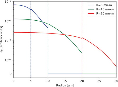
Fig. 3. Evolution of the fuel grain and graphite temperatures for the EOS pulse with HEU fuel for grain radius of (a) R = 5 μm and (b) R = 20 μm.
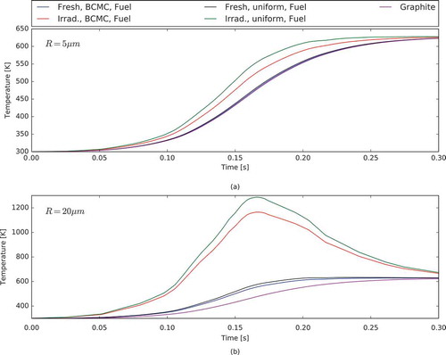
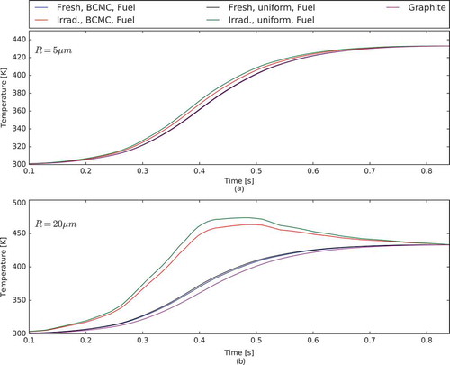
Fig. 4. Evolution of the fuel and graphite temperatures for the E4 pulse and HEU fuel for grain radius of (a) R = 5 μm and (b) R = 20 μm.
The behavior of LEU and HEU fuel is considerably different. The fuel grain and graphite temperatures for the EOS pulse in LEU fuel are depicted in . The fuel grains do not get as hot as in the corresponding HEU configuration leading to a smaller . This distinct behavior is caused by the larger density of fuel grains in LEU fuel leading to a power per fuel grain that is roughly four times smaller than the corresponding HEU value. In effect, only significant temperature differences between fuel grain and graphite occur if the transient inserts sufficient reactivity, the fuel grains are large, and the fuel is irradiated. As fuel grains for LEU configurations target a radius around R = 5 μm, significant
may not occur in prospective LEU fuel.
Ballistic transport of energy is an important mechanism for irradiated fuel. We assess the impact of ballistic transport of energy by comparing two models. First, we use a BCMC-informed source term that models ballistic energy transfer, and second, we assume local energy deposition from fission fragments, i.e., a uniform distribution in the fuel and zero everywhere else. Results obtained with these two models are significantly different if the graphite around the fuel grain is irradiated. The difference between the computed temperatures is more pronounced for stronger pulses and larger fuel particles. Predictions of strong pulses in irradiated fuel that neglect ballistic energy transfer may overestimate the fuel temperature leading to an overconservative estimate of TREAT’s transient capabilities. For fresh fuel, ballistic transport has a negligible effect on the temperature of the fuel.
Fig. 5. Evolution of the fuel and graphite temperatures for the EOS pulse and LEU fuel for grain radius of (a) R = 5 μm and (b) R = 20 μm.
IV.B. Evaluation of Feedback Mechanisms for HEU and LEU TREAT Fuel
The focus of this section is to investigate the relevant feedback mechanisms for HEU and LEU fuel. MAMMOTH offers the flexibility of using arbitrary temperature fields for cross-section interpolation. Within this work, cross sections are interpolated using separate graphite and fuel grain temperatures. In relation to Eq. (9), a cross section interpolated at graphite temperature and fuel temperature
is denoted by
; i.e., the first argument denotes which temperature field is supplied for interpolating the fuel cross section, and the second argument denotes the temperature field supplied for the graphite cross section. Supplying different feedback temperatures either includes or omits that feedback mechanism. For example, the case of evaluating the cross sections at the multiscale graphite and fuel grain temperatures,
and
, respectively, is denoted by
. To produce simulation results without time lag, the homogeneous reactor mixture temperature
is supplied in place of the fuel grain and moderator temperature
. This case corresponds to a scenario where fuel and graphite are perfectly intermixed. Elimination of all feedback corresponds to the case
with both temperatures held at a constant 300 K.
In order to obtain comparable pulses from the HEU and LEU assemblies, the initial reactivity insertion is adjusted to obtain the same reactor period for the case . Without any feedback, the period is found by fitting the power density profile to an exponential function. To at least three decimal places, the HEU and LEU model’s period is identical with a value of 33.725 ms.
To determine if the proposed method captures feedback from spectral shift determined by the moderator temperature and Doppler broadening feedback from the fuel grain temperature
, each source is isolated during a MAMMOTH simulation. To this end, the cases
,
, and
are compared.
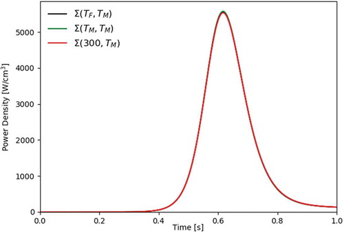
includes the feedback from both fuel and graphite while
removes the effect of Doppler feedback. As expected, shows the HEU feedback is dominated by spectral shift. The power trace does not change significantly if the feedback temperature provided to the fuel grain cross sections is changed from
to
or set constant to
K.
Fig. 6. The 20-μm-radius HEU model pulse power density varying temperature feedback sources.
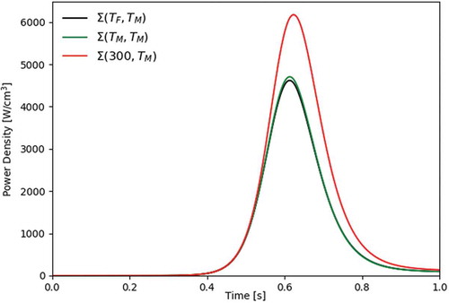
Corresponding power traces for the LEU configuration are presented in . In contrast to the HEU configuration, the fuel grain’s contribution to the feedback is clearly significant as is evident from the large difference of the and
to the
power traces. The differing degree of significance of Doppler feedback between the two configurations is embodied in the lack of change in the HEU model between the
and
traces and the significant reduction in peak power for the LEU configuration.
Fig. 7. The 20-μm-radius LEU model pulse power density varying temperature feedback sources.
In , the peak power densities for the three cases are assembled for different grain sizes. As the fuel grain radius decreases for both the HEU and the LEU models, the temperature of the fuel grain approaches the temperature of the moderator reducing the effect of time lag. The reduced time-lag effect is illustrated by the column values approaching the values in the
column as the fuel grain radius decreases.
TABLE VI LEU TREAT Fuel Atomic Density Values (×1024/cm3)*
TABLE VII Varying Grain Radius Effect on Average Peak Power Density*
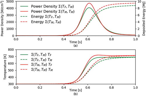
In Sec. IV.A, results show that significant temperature differences between fuel grains and graphite moderator may occur for the LEU configuration during high-powered pulses for irradiated fuel with larger fuel grains. It remains to be investigated if can lead to a significant change in the power trace for LEU fuel under these conditions. The largest considered LEU fuel radius of 20 μm is selected to apply a reduced thermal conductivity layer as described in Sec. IV.A and repeat the previously discussed simulations. Power traces, fuel temperature, and graphite temperature are presented in . A significant effect of feedback from
is seen on the peak power and deposited energy of the transient. In ,
evaluates the fuel cross sections at the hotter fuel temperature, while the
case ignores
assuming all materials are at the graphite temperature. The former case includes more Doppler feedback leading to a reduced reactor power. These results demonstrate that the immediate equilibrium assumption, namely,
, is not valid throughout the considered parameter space. However, it breaks down only for large reactor powers, graphite irradiation damage, and large grain radii.
Fig. 8. Pulse of an irradiated 20-μm LEU model varying fuel grain feedback showing (a) power density and deposited energy and (b) average feedback temperature results.
To verify that the observed effect of the fuel temperature change is consistent with the computed cross sections, infinite medium eigenvalues are computed for HEU and LEU fuel at isothermal conditions; i.e., both fuel grain and graphite temperatures are fixed at different values. The goal of this exercise is to show that the LEU fuel temperature feedback is strong and negative, while the HEU fuel temperature feedback is much smaller in magnitude.
Infinite medium eigenvalues are computed on a temperature grid spanned by and
every 10K starting at 305K. Eigenvalues for both HEU and LEU fuel assemblies with
fixed at 305K are depicted in . Increasing the fuel temperature always decreases the LEU eigenvalue, but for the HEU fuel, increasing the fuel temperature does not change the reactivity to a statistically significant degree; i.e., the overall change of eigenvalue with temperature does not exceed 2σ.
Fig. 9. The 20-μm-radius eigenvalue results ( error) for varying
.
The discontinuities in slope in the eigenvalue curves are caused by linear interpolation of cross sections between grid state points in the cross-section library spaced every 100K. It should be noted that this is an artifact of the cross-section interpolation procedure and not caused by the physics of the problem. Feedback coefficients are calculated as the derivative of reactivity with respect to either the fuel or graphite temperature; the sign and magnitude of the feedback coefficient are embodied in the slope of the eigenvalue-versus-temperature curve. It is calculated as
where is either
or
. For computing
,
is perturbed by
, and the change in reactivity is then computed by
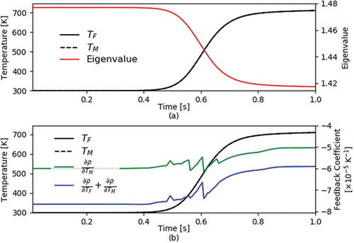
The best estimate of the average fuel grain radius is around 10 μm for the currently operating TREAT reactor.Citation18,Citation26 For the LEU fuel, avoiding increased Doppler feedback from elevated fuel temperatures puts a high premium on small fuel grains, but radiation damage around the outer fuel radius requires the fuel grain size to be ≥5 μm (CitationRef. 5). Therefore, for further investigation, the transient behavior of the 10-μm HEU fuel and the 5-μm LEU fuel is set as the prototypical models. With evaluating cross sections using microscale fuel grain and graphite temperatures, i.e., , and keeping the same reactor period as before, and show the time evolution of the eigenvalue, average graphite and fuel grain temperatures, and feedback coefficients throughout the pulse for the HEU and LEU models, respectively. The feedback coefficients are calculated with the current
and
combination at that time with respect to both
and
. The influence of the discontinuous derivative of the eigenvalue caused by linear interpolation of the cross sections manifests itself as discontinuities in slope in the feedback coefficient curves whenever 400K, 500K, 600K, or 700K is crossed by either material temperature. Comparing the sum of the feedback coefficients to only the feedback coefficient with respect to changing the moderator temperature illustrates the contribution of the fuel grain feedback temperature that can be deduced as the difference between the two curves.
Fig. 10. The 10-μm-radius HEU model: (a) eigenvalue and (b) feedback coefficients compared with the average feedback temperatures.
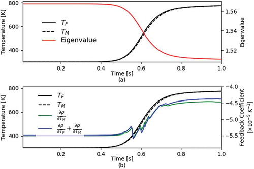
Fig. 11. The 5-μm-radius LEU model: (a) eigenvalue and (b) feedback coefficients compared with the average feedback temperatures.
For the HEU model of , the magnitude of the fuel grain temperature feedback coefficient is much smaller than the magnitude of the graphite temperature feedback coefficient reinforcing the conclusion that the HEU model is dominated by spectral shift with the contribution of the fuel grain feedback coefficient, positive or negative, being negligible.
In contrast, for the LEU case both graphite and fuel temperature coefficients, depicted in , are negative and of comparable order of magnitude. The fuel grain contributes roughly 20% to the sum of the feedback coefficients. These findings are important for understanding the physics governing the transient behavior of the LEU model and how it differs from the HEU model. The main difference between the HEU and LEU models is the graphite temperature feedback coefficient for the HEU model is orders of magnitude larger than the fuel grain temperature coefficient. The LEU model’s fuel grain temperature coefficient is on the same order of magnitude as the moderator temperature coefficient. These characteristics have direct implications on the design and operation of a converted LEU TREAT reactor. In Sec. IV.C, performance metrics for the LEU model are evaluated that would directly translate into design and operational guidance if applied to a more comprehensive LEU model.
IV.C. LEU Fuel Element Performance
In this section, the impact of the Doppler feedback on important operational parameters of the LEU fuel element are investigated. The investigation scope is limited to fresh fuel. The initial reactivity insertion, the peak power density, the peak time, the deposited energy before a cutoff time, and the full-width at half-maximum (FWHM) of the power trace are selected as key parameters. The key parameters directly relate to a safe and successful operation of the TREAT reactor. Arguably, the power density and energy deposition in the experiment are more important quantities to be matched between the HEU and LEU configurations. However, given the limited geometric complexity of the simplified model, the core power and energy deposition are used as surrogates. The change from HEU fuel to LEU fuel affects the relationship of the core to the experiment as well as the pulse behavior, but those considerations are beyond the scope of this work of just considering the change of a single fuel element. The FWHM is desired to closely match typical pulse width values from relevant reactor concepts under postulated accident conditions.
In Sec. IV.B, HEU and LEU model predictions are always compared with matching reactor periods. In expanding this work, we select one key parameter that we match between the HEU and LEU configurations, while the remaining parameters are allowed to vary. We then compare the computed HEU and LEU values of the remaining parameters. The importance of this analysis is to recognize trends of operational limitations of the converted LEU TREAT in terms of equivalent key parameters achieved with the HEU TREAT model.
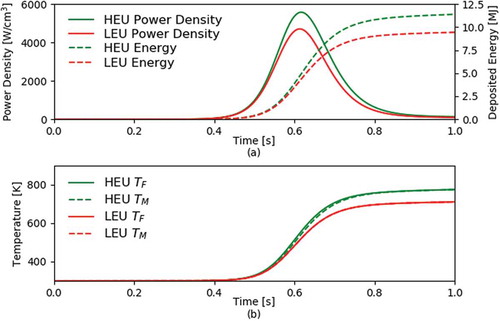
First, reactor periods for 10-μm HEU and 5-μm LEU assemblies are matched. plots the power density, deposited energy, and fuel grain and graphite temperature traces. The HEU model’s peak power density and deposited energy are roughly 15.6% larger than the corresponding LEU model’s values even though the LEU model required about a 8.4% higher initial reactivity insertion relative to the HEU’s value in order to match the same period.
Fig. 12. Pulse of matching initial periods for the 10-μm HEU model and the 5-μm LEU model with (a) power density and deposited energy and (b) average feedback temperature results.
Proceeding on to the discussion of the results of matching the peak power densities and deposited energies of the LEU and HEU models, the resulting changes in the key performance parameters for these scenarios are assembled in . The 10-μm-radius HEU fuel grain model’s solution provides the following key parameter values: an initial reactivity insertion of 2.768 , a peak power density of 5571 W/cm3 located at 0.618 s, a deposited energy at 1 s of 11.38 MJ, and a FWHM of 157 ms.
TABLE VIII LEU Model Effects from Matching the HEU Model Target Values
As the TREAT facility is tasked with experiments requiring certain target values that are satisfied by the HEU configuration, shows possible ramifications of LEU conversion on operational strategies if the interaction between the core and the experiment is assumed to be the same for the HEU fuel and LEU fuel. For example, if the successful completion of an experiment requires reaching a certain energy deposition after 1 s, LEU TREAT might require an additional insertion of 20.1% of reactivity relative to the HEU TREAT. This additional reactivity might increase the peak power density by 13.3%, move the peak to earlier in the transient by 11.7%, and decrease the FWHM by 12.7%.
Overall, when comparing the HEU and LEU models, the feedback is stronger for the LEU model during a pulse as seen in having a more negative feedback coefficient than . Because of the differing feedback mechanisms, creating the exact same pulse shape is not possible. The presented feedback model provides insight into the behavior of the converted TREAT reactor by faithfully modeling the relevant feedback mechanisms. Including the effect of LEU conversion on the experiment is possible in MAMMOTH, and hence, the feedback model can provide predictions on how important figures of merit are connected to the LEU’s operational parameters.
V. CONCLUSION
This work presents a coupled multiphysics, multiscale feedback model of a simplified TREAT fuel element configuration. The model includes microscopic heterogeneity effects on length scales comparable with the size of a fuel grain (10 μm) within a macroscopic neutronics simulation with characteristic length scales on the order of 1 cm. The key difference to standard transient neutronics models with feedback is the computation of cross sections at distinct fuel grain and graphite temperatures that are computed within the multiscale approach. BCMC-informed heat source distributions model ballistic energy transfer in the vicinity of fuel grains.
The essential concept of the proposed feedback model is not limited to application in MAMMOTH spatial kinetics calculations. Point-kinetics models can readily include the two-temperature feedback model. The difference between spatial and point kinetics is the inclusion of spatial variation of the power density in the transient simulation.
Using transient powers reported by CitationRef. 3, significant differences between the fuel and moderator temperature are shown to occur during TREAT operation for fast transients with high peak power, large fuel grains, and irradiation. The temperature differences are larger for HEU than for LEU because the power per grain is significantly smaller for LEU fuel. While is significant for HEU fuel well inside TREAT’s operating regime, its effect is only significant for LEU configurations for fuel grains that are larger than the targeted size of 5 μm and have accumulated fission-fragment damage around the fuel grain circumference. Ballistic energy transfer is shown to be important for the evolution of the fuel temperature in the presence of degraded thermal properties of the graphite in the vicinity of the fuel grain.
The feedback model is deployed to investigate the importance of fuel and graphite temperature differences. For HEU fuel, neglecting does not alter the trajectory of the power to any significant degree. In contrast, the power trajectory of the LEU fuel is sensitive to
, but the magnitude of
is smaller. Consequently, taking
into account is required if the transient inserts sufficient reactivity, the fuel grain is sufficiently large, and the graphite has been irradiated. These conclusions are in agreement with the computed graphite and fuel grain temperature feedback coefficients for HEU and LEU fuel.
The LEU model predicts the change in key performance parameters when matching either the HEU model’s reactor period, peak power density, or deposited energy at 1 s. These results have important implications on both the design and operation of a converted TREAT LEU reactor because it is highly desirable to predict the capability envelope of LEU TREAT for comparison with the HEU envelope. The LEU model requires more reactivity insertion (about 0.233, 0.414, and 0.556 for matching period, peak power density, and deposited energy, respectively) than the HEU model indicating more excess reactivity may be needed. Further, the pulse’s FWHM is smaller for the LEU model due to stronger feedback with increased reactivity insertion causing smaller energy deposition for cases where deposited energy is not forced to be identical.
The scope of this work is limited to short transients where heat conduction on the engineering length scale can be neglected. Slower shaped transients require consideration of heat conduction on the centimeter length scale that is not currently included in the multiscale model. Future work may extend the method to investigate the importance of time lag for slow, shaped transients for both HEU and LEU fuel.
As a proof of principle, the developed model is exercised for a simplified, semi-infinite TREAT fuel element problem illustrating the method’s unique feedback and distributed heat source considerations. For obtaining more quantitatively reliable conclusions, a more comprehensive TREAT LEU model will need to be modeled in the future taking into consideration the BCMC distributed heat source and irradiation changes to the graphite around the fuel grain. Both the HEU and the LEU models should be compared in terms of metrics affecting an experiment placed in TREAT.
Acknowledgments
This work was supported through the INL Laboratory Directed Research & Development Program under grant number 16-010. This manuscript has been authored by Battelle Energy Alliance, LLC under contract number DE-AC07-05ID14517 with the U.S. Department of Energy.
References
- “DOE National Laboratory Resumes Operation of U.S. Transient Test Reactor,” U.S. Department of Energy; https://www.energy.gov/articles/doe-national-laboratory-resumes-operation-us-transient-test-reactor (current as of June 6, 2018).
- G. FREUND et al., “Design Summary Report on the Transient Reactor Test Facility (TREAT),” ANL-6034, Argonne National Laboratory (1960).
- K. MO et al., “Heat Transfer Simulations of the UO2 Particle–Graphite System in TREAT Fuel,” Nucl. Eng. Des., 293, Supplement C, 313 (2015); https://doi.org/10.1016/j.nucengdes.2015.08.009.
- J. D. BESS and M. D. DeHart, “Baseline Assessment of TREAT for Modeling and Analysis Needs,” INL/EXT-15-35372, Idaho National Laboratory (2015).
- H. M. CONNAWAY et al., “Analysis of the TREAT LEU Conceptual Design,” ANL/RTR/TM-16/1, Argonne National Laboratory (2016).
- S. SCHUNERT et al., “Heat Source Characterization in a TREAT Fuel Particle Using Coupled Neutronics Binary Collision Monte-Carlo Calculations,” Proc. Int. Conf. Mathematics & Computational Methods Applied to Nuclear Science & Engineering (M&C 2017), Jeju, Korea, April 16–20, 2017.
- A. X. ZABRISKIE et al., “Self-Limiting Transient Pulse Simulation Method Exhibiting Time Lag Phenomenon Using MAMMOTH,” Proc. Reactor Physics Paving the Way Towards More Efficient Systems (PHYSOR 2018), Cancún, México, April 22–26, 2018.
- N. WOOLSTENHULME et al., “Capabilities Development for Transient Testing of Advanced Nuclear Fuels at TREAT,” INL/CON-16-37608, Idaho National Laboratory (2016).
- F. N. GLEICHER et al., “The Coupling of the Neutron Transport Application RATTLESNAKE to the Nuclear Fuels Performance Application BISON Under the MOOSE Framework,” INL/CON-14-31079, Idaho National Laboratory (2014).
- Y. WANG et al., “Demonstration of MAMMOTH Fully Coupled Simulation with the Godiva Benchmark Problem,” Proc. Int. Conf. Mathematics & Computational Methods Applied to Nuclear Science & Engineering (M&C 2017), Jeju, Korea, April 16–20, 2017.
- M. D. DeHart, B. A. BAKER, and J. ORTENSI, “Interpretation of Energy Deposition Data from Historical Operation of the Transient Test Facility (TREAT),” Nucl. Eng. Des., 322, 504 (2017); https://doi.org/10.1016/j.nucengdes.2017.07.019.
- J. ORTENSI et al., “Full Core TREAT Kinetics Demonstration Using Rattlesnake/BISON Coupling Within MAMMOTH,” INL/EXT-15-36268, Idaho National Laboratory (2015); https://doi.org/10.2172/1261006.
- A. L. ALBERTI et al., “Steady State Modeling of the Minimum Critical Core of the Transient Reactor Test Facility,” PhD Thesis, Oregon State University (2016).
- Y. WANG, S. SCHUNERT, and V. LABOURE, “Rattlesnake Theory Manual,” INL/EXT-17-42103, Idaho National Laboratory (2017).
- J. ORTENSI et al., “A Newton Solution for the Superhomogenization Method: The PJFNK-SPH,” Ann. Nucl. Energy, 111, 579 (2018); https://doi.org/10.1016/j.anucene.2017.09.027; http://www.sciencedirect.com/science/article/pii/S0306454917303079 ( current as of June 6, 2018).
- M. CHADWICK et al., “ENDF/B-VII. 1 Nuclear Data for Science and Technology: Cross Sections, Covariances, Fission Product Yields and Decay Data,” Nucl. Data Sheets, 112, 12, 2887 (2011); https://doi.org/10.1016/j.nds.2011.11.002.
- J. J. DUDERSTADT and L. J. HAMILTON, Nuclear Reactor Analysis, Vol. 1, Wiley, New York (1976).
- L. J. HARRISON, “TREAT Neutron Radiography Facility,” Neutron Radiography, pp. 251–256, Springer.
- D. L. HETRICK, “The Effect of Fuel Particle Size on the Transient Behavior of a Homogeneous Graphite Reactor,” NAA-SR-210, North American Aviation, Inc. (1952).
- M. L. WILLIAMS, “Resonance Self-Shielding Methodologies in SCALE 6,” Nucl. Technol., 174, 2, 149 (2011); https://doi.org/10.13182/NT09-104.
- D. SCHWEN et al., “Molecular Dynamics Simulation of Intragranular Xe Bubble Re-Solution in UO2,” J. Nucl. Mater., 392, 1, 35 (2009); https://doi.org/10.1016/j.jnucmat.2009.03.037.
- D. GASTON et al., “MOOSE: A Parallel Computational Framework for Coupled Systems of Nonlinear Equations,” Nucl. Eng. Des., 239, 10, 1768 (2009); https://doi.org/10.1016/j.nucengdes.2009.05.021.
- D. R. GASTON et al., “Physics-Based Multiscale Coupling for Full Core Nuclear Reactor Simulation,” Ann. Nucl. Energy, 84, 45 (2015); https://doi.org/10.1016/j.anucene.2014.09.060.
- J. LEPPÄNEN et al., “The Serpent Monte Carlo Code: Status, Development and Applications in 2013,” Ann. Nucl. Energy, 82, 142 (2015); https://doi.org/10.1016/j.anucene.2014.08.024.
- K. MO et al., “Effect of Reactor Radiation on the Thermal Conductivity of TREAT Fuel,” J. Nucl. Mater., 487, 453 (2017); https://doi.org/10.1016/j.jnucmat.2017.02.003.
- J. HANDWERK and R. LIED, “The Manufacture of the Graphite-Urania Fuel Matrix for Treat,” ANL-5963, Argonne National Laboratory (1960).