
 ?Mathematical formulae have been encoded as MathML and are displayed in this HTML version using MathJax in order to improve their display. Uncheck the box to turn MathJax off. This feature requires Javascript. Click on a formula to zoom.
Abstract
Comet is a general-purpose, heavy-duty, vertical-lift assembly designed for flexibility in conducting a variety of critical experiments. It is currently located at the National Criticality Experiments Research Center (NCERC) in Nevada. In the past, Comet resided at Technical Area-18 in Los Alamos, New Mexico, as part of the Los Alamos Critical Experiments Facility (LACEF). The Comet assembly was relocated to NCERC in 2008 and became fully operational in June of 2011. The first critical experiment performed on Comet at NCERC was a verification of one of the previous configurations of the Zeus experiment series. Over the next 10 years, many additional experiments followed including other Zeus configurations as well as completely new designs. This paper discusses the Comet vertical-lift assembly, the transition from LACEF to NCERC, and a selection of experiments that have been performed on Comet during its first 10 years of operation at NCERC.
I. INTRODUCTION
Comet is a general-purpose, heavy-duty, vertical-lift assembly machine used to conduct critical and subcritical experiments, nuclear safety studies, and criticality safety training.Citation1 The machine consists of a movable platen and an upper, stationary platform. Operations are performed by installing two subcritical configurations made up of fissile material and reflectors on both platforms and then raising the lower platen toward the stationary platform. When fissile material is present, reactivity can be added by raising the lower platen and decreasing the distance between the two portions of the system or by inserting fissile material into a reflector. shows the number of operational days of the Comet assembly through the first 10 years of the National Criticality Experiments Research Center (NCERC). Among the device’s advantages is its operational flexibility. Comet is able to accommodate a plethora of configurations, from a 6500-kg Cu reflector for the Zeus experiments (shown in ) to the Kilowatt Reactor Using Stirling TechnologY KRUSTY) space reactor for the joint National Aeronautics and Space Administration (NASA) and National Nuclear Security Administration (NNSA) Kilopower Project, to a critical configuration of less than 300 g of 235U reflected by beryllium.Citation2
Fig. 1. Number of Comet operational days per year
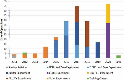
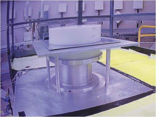
Fig. 2. Photograph of Comet at TA-18 during the initial Zeus series
The Comet assembly machine has a long and storied history of operations, beginning in the 1950s at the Los Alamos Critical Experiments Facility (LACEF) at Los Alamos National Laboratory (LANL). In 2004, operations at LACEF ended, and Comet, along with the other critical assembly machines Planet, Flattop, and Godiva IV, was disassembled and moved to the newly established NCERC at the Nevada National Security SiteCitation1 (NNSS). This transition from LACEF to NCERC marked the end of an era of critical experiments and the beginning of a new chapter of experiments.Citation3
II. COMET HISTORY AT LACEF
The need for critical experiments at LANL arose during the Manhattan Project. The first of these experiments began in May of 1944 with the construction of the first water-boiler reactor at the Omega Site. One year later, in the aftermath of the death of physicist Harry Daghlian in a criticality accident at the Omega Site, critical experiments at the laboratory were moved to the Pajarito Site, also known as Technical Area-18 (TA-18). This would be the home of LACEF for decades to come. Unfortunately, in the first year of operations at TA-18, Louis Slotin, a Canadian physicist, well respected for his expertise in critical experiments and work during the Manhattan Project, died as a result of a criticality accident. This incident led to the immediate cessation of all hands-on experiments in which a critical configuration could be achieved.Citation4
Because of the great scientific value that criticality experiments provided to LANL’s mission, it was determined that the experiments would continue but would require using safer and more reproducible methods. To meet this criterion, experimenters considered using hot-cell–type manipulation of experiments using thick walls to reduce dose in the case of an accident or using true remote control with a quarter-mile separation between the operators and the experiment. They also chose between using complex robots that could duplicate human adaptability and dexterity and using more conventional machines limited to simpler motions. Ultimately, it was decided to continue operations using remotely controlled simple machines that relied on gravity as a fail-safe mechanism.Citation5
Initial LACEF operations involved assisting the nuclear weapons program to establish criticality safety guidance for workers handling, storing, transporting, and assembling weapons in order to prevent criticality accidents. Additional experiments provided data to aid in reactor design. In the 1950s more experimental assemblies were constructed to broaden the capabilities at LACEF including the focus of this paper: the Comet assembly.
The Comet assembly was originally called Haley’s Comet after its designer, Jano Haley.Citation5 The assembly was initially used for safety tests for the weapons program and used to provide critical mass data for cylindrical geometries. A selection of interesting experiments performed on Comet at LACEF are summarized below.
II.A. Jemima and Other Early Critical Experiments on Comet
One of the earliest series of critical experiments performed on Comet was the Jemima Critical Assemblies, conducted in 1952. The fissile material involved in these experiments was a set of thin, uranium cylindrical plates called the Jemima plates, each weighing around 6 kg. Plates of highly enriched uranium (HEU) and natural uranium (NU) were interlaced to achieve average core enrichments of 37.7 wt% and 53.6 wt%. Before the Jemima series of experiments began, the experimenters intended to create an assembly of only HEU plates; however, because of an error during the approach to critical, a super-prompt-critical excursion occurred. There was no damage to the fuel or machine.Citation5 This accidental excursion helped lead to prompt burst operations with the Lady Godiva assembly and eventually the development of dedicated fast burst assemblies such as Godiva IV.
In 1966, Comet achieved criticality with a mere 290 g of 235U by layering HEU foils with polyethylene plates, all enclosed in a beryllium reflector. At the time, this was the lowest amount of fissile material used to achieve criticality and may still be to this day.Citation5
In 1979, Comet was used to evaluate 242Pu cross sections and took measurements of various arrangements of interest to criticality safety engineers.
In the 1980s, many experiments utilized the Thor Core, a 9.8-kg 239Pu sphere in a thorium reflector. There was much interest at the time in thorium as a breeding material for 233U in place of uranium-to-plutonium breeding.Citation6 The Thor Core is still used to this day at NCERC (CitationRef. 7).
II.B. Little Boy Mock-Up
Also in the 1980s, Comet was used to reevaluate ground doses from the Hiroshima bombing. A mock-up of the Little Boy core was installed on Comet, and then, fast neutron leakage was recorded at different angles to better understand dose distribution from the weapon.Citation8 The experiment involved bringing two fissile masses closer together. It used movable detectors to measure the angular distribution of the neutron flux being emitted from the system. is a diagram of this experiment. This experiment provided scientists the requisite data without the need for a full-scale test, which could not be performed due to the limited testing of the Partial Test Ban Treaty of 1963 (CitationRef. 9).
Fig. 3. Diagram of the mock-up of Little Boy on Comet
II.C. Zeus Experiments
In the 1990s, the increasing need for nuclear data in the intermediate-energy range prompted the design of the Zeus experiments. Achieving an intermediate-energy spectrum is difficult, as hydrogenous moderating materials such as polyethylene or Lucite tend to be too effective at thermalizing neutrons. Large systems are required to allow many scattering interactions, and materials with a moderate-Z number are needed to moderate fission neutrons without completely thermalizing them. To limit the size of the core for Zeus, large copper reflectors were designed to surround the assembly, reflecting neutrons back to undergo further scattering. The Comet machine had to be completely refurbished to support the significant weight of the copper reflector and to lift the lower stack of Jemima plates and interstitial materials. The structure was strengthened, the lifting mechanisms were replaced, and a new control system was installed.
Jemima plates were chosen for the fuel, and graphite moderators were selected to create the initial intermediate spectra. The name Zeus, after the Greek god who frequently changed forms, was chosen to reflect the plan of incorporating a wide range of materials to create varied spectra, initially focusing on the intermediate-energy spectra but later spanning from thermal to fast neutron spectra. from HEU-MET-INTER-006 shows a Zeus core with graphite moderator and copper reflectors. shows a cutaway view of the reflector.
Fig. 4. Diagram of a Zeus core, featuring HEU, graphite (G), copper reflectors (R), alignment tube (AT), platen, and platen adaptor plate (PAP)
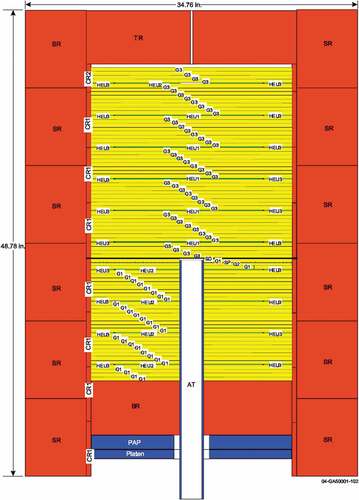
Fig. 5. Diagram of a typical Zeus experiment with the movable platen retracted out of the reflector
The initial Zeus campaign, which took place from 1999 through 2004, continued until the end of operations at TA-18. Zeus maintains a notable legacy, as it is the primary benchmark used in the validation of intermediate-energy nuclear data for 235U, and the experiment design has heavily influenced later experiments at NCERC targeting intermediate-energy spectra.Citation10–12
III. MACHINE OVERVIEW
Comet was designed to perform accurate, reproducible configurations with a wide range of experimental configurations and masses. The machine allows for nuclear materials, moderators, and reflectors, separated on an upper stationary platform and a lower movable platform, to be brought together in a stepwise fashion to achieve criticality. The weight limit on the lower movable platform is 907 kg (2000 lb) while the upper platform can support up to 9072 kg (20 000 lb). This makes Comet the heavy-duty machine, as opposed to the other smaller, light-duty, vertical-lift machine at NCERC: Planet.
The movable portion of Comet consists of three mechanisms that operate in a telescoping fashion. The hand-crank table holds the lower portion of the experiment. It is driven up and down by a manually operated gear mechanism. This mechanism allows the assembly to be adjusted for configurations with different heights of components on the lower stack. When all movable components are fully inserted, the hand-crank mechanism ensures the height of the lower stack is at the correct position in relation to the upper stack. Below the hand-crank table is the ram table. This table is supported by back-to-back hydraulic rams, which extend simultaneously to provide the coarse movement for the machine, as well as the required redundant safety shutdown mechanism. The ram table is mounted on the platen table. The platen table is driven by a stepper motor, which provides the fine control for the lifting mechanism. Control system interlocks ensure that the platen table can be moved only after the ram table has been fully inserted to its in-limit. The two hydraulic rams have a maximum travel of 1.5 in. each, for a total of 3 in., and the stepper motor has a maximum travel of 25 in. Combined, this results in a total of 28 in. of vertical travel. The insertion speed of the stepper motor can be modified as a function of the separation distance, down to 1 mil/s. This ensures that reactivity can be added at a very slow speed, if desired for the experiment. A load cell on the lower platform measures the weight on the platen, which can be used to indicate when the lower stack contacts the upper stack and the assembly is fully closed if the core is not visible through the reflector configuration.
Operations of Comet are performed using two methods. One involves installing fissile material on both the top and the bottom platforms and then raising the lower platen to decrease the distance between the two portions of the system. The second method involves installing fissile material on the lower platen and reflector material on the upper platform (or vice versa) and then raising the lower platen to insert fissile material into the reflector. When loading materials for unknown configurations, experimenters follow the 3/4 Rule and the Halfway Rule. The 3/4 Rule states that for hand-stacking operations, each stack may comprise no more than 3/4 of the predicted critical configuration. The Halfway Rule states that the number of units added in any one step shall not exceed halfway between the number of units currently on the stack and the number of units predicted to reach critical. These rules provide a margin of safety to prevent a system from unintentionally going critical with experimenters present.
IV. STARTUP OF COMET AT NCERC
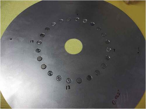
Comet was the second of the four critical assembly machines to achieve criticality at NCERC with first critical in August of 2011. The first critical experiment on Comet at NCERC repeated the unmoderated Zeus configuration previously performed at LACEF (CitationRef. 13). In addition to providing a confirmatory measurement, activation foils and fission foils were included between the fuel layers near the center of the core and irradiated.Citation14 These foils, seen in , provide useful data such as spectral indices and fission product yield during irradiations performed in 2011 and 2012 (CitationRef. 15). Foils included HEU, depleted uranium, Pu, Ir, Au, Mo, W, Ti, Sc, Ni, V, Ga, and Fe. Some foils were placed in cadmium covers. Rossi-alpha measurements were also performed with 3He tubes located in the alignment tube to determine the prompt neutron decay constants of the system.Citation16
Fig. 6. Photograph of activation and fission foils loaded on a sample plate for irradiation in a Zeus HEU core
V. COMET OPERATIONS AT NCERC
V.A. Benchmark Experiments
Since restarting Comet operations at NCERC in 2011, several experiments have been performed that serve as the basis for benchmarks in the International Criticality Safety Benchmark Evaluation Project (ICSBEP) handbook.Citation17 This handbook is a compendium of over five thousand evaluations of critical, near-critical, and subcritical experiments. Data from these experiments are used by criticality safety engineers around the world to validate calculation techniques and establish subcritical margins for fissionable material–handling operations. In addition, these benchmark experiments are used for nuclear data and computational methods validation. Benchmarks performed on Comet are listed in .
TABLE I ICSBEP Comet Benchmarks
V.B. Japan Atomic Energy Agency Collaboration
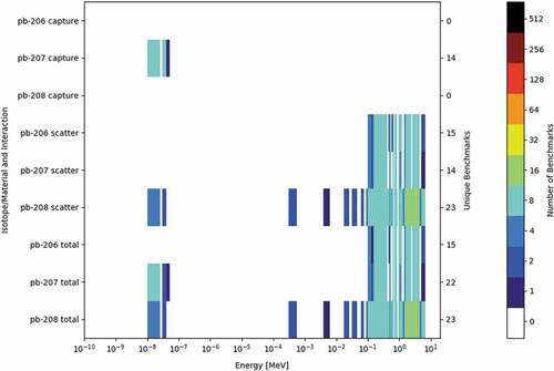
A series of measurement campaigns took place between 2015 and 2019 in a collaboration between LANL and the Japan Atomic Energy Agency. This series of experiments supported Japan’s research into designing an accelerator-driven transmutation system for spent nuclear fuel.Citation18 The designers need nuclear data related to lead because a lead-bismuth eutectic is expected to be used as a coolant for the transmutation system. Lead-bismuth eutectics are of great interest in fast reactor and accelerator-driven subcritical systems because they have a low melting temperature, high volumetric heat capacity, and low neutron absorption cross section. Therefore, additional data on lead void reactivity worth for uranium and plutonium systems allow designers to perform an accurate safety analysis. However, there are only a small number of benchmarks in the ICSBEP handbook that are sensitive to lead as shown by (CitationRef. 19). These experiments have already provided useful experimental information,Citation20–24 and three separate ICSBEP benchmarks based on the experiments are in varying stages of submission to the ICSBEP handbook.Citation25,Citation26
Fig. 7. The number of ICSBEP benchmarks sensitive to lead for different energies and isotopes
Three different fuel combinations were investigated as part of this campaign. The three systems designed used HEU Jemima plates (designated as Zeus HEU/Pb), an HEU Jemima plate and NU plate combination to form an effective Intermediate Enriched Uranium (IEU) system (designated as Zeus IEU/Pb), and Zero Power Physics Reactor (ZPPR) Pu plates (designated as Jupiter). All three of the core configurations were surrounded by the thick copper reflectors used in the original Zeus experiments.Citation10–12
Both uranium cores included aluminum barrier sheets that surrounded each lead plate in order to reduce cross contamination between the fuel and lead. The plutonium core also included aluminum sheets around the lead components. Voids were introduced in the lead moderator of these cores by substituting aluminum spacers for the central portion of the lead and aluminum sheets in a selected number of units within the core. The same set of aluminum spacers, similar to that shown in , was used in the Zeus IEU and HEU experiments. A rectanglular spacer was designed for the Jupiter experiment. Each aluminum spacer for the Zeus configurations replaced two inner lead disks and their associated aluminum sheets. Each aluminum spacer for Jupiter replaced one lead plate and its associated aluminum sheets. Both types of spacers were designed such that the aluminum mass in the core did not change when substituting the spacer for lead. shows the change from the Zeus HEU reference case (no spacers) to the Zeus HEU 8V case (eight spacers).
Fig. 8. Photograph of an aluminum spacer used to introduce voids in the lead moderators of the Zeus HEU and IEU cores
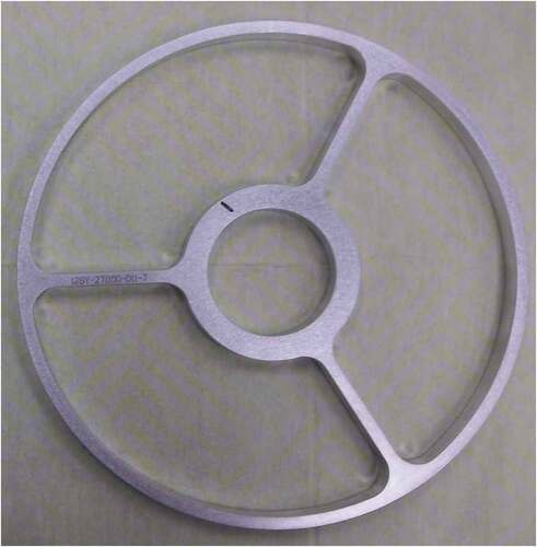
Fig. 9. HEU/Pb core depicted in (a) the reference configuration and (b) the 8V configuration with voids introduced by the replacement of lead with eight spacers
Early Zeus HEU/Pb experiments were conducted in 2015/2016, and Rossi-alpha measurements were performedCitation27; however, the benchmark configuration was executed in August 2018. Containing only HEU fuel, it had an average uranium enrichment of 93.18 wt%. The HEU/Pb base unit consists of one HEU layer and four lead layers as shown in . There was a total of 16 units in the HEU configuration with small adjustments made to the outermost units (e.g., replacing fuel with Al disks/rings or reducing the number of lead layers) to reach the desired excess reactivity.
Fig. 10. Diagram of base unit of the Zeus HEU/Pb experiment
The Zeus IEU benchmark configuration was executed in January 2017 and had an average uranium enrichment of 22.9 wt%. The base unit for this core consisted of a single HEU layer, a single NU layer, and two lead layers, and it follows the same rough pattern as the HEU/Pb core, as shown in . There was a total of 15 units in the Zeus IEU configuration. Because of weight limits on the platen, the outer portions of the NU layers were replaced with aluminum on the bottom stack. Other adjustments were made to the outermost units to reach the desired reactivity. As in the Zeus HEU configuration, Al spacers, shown in , were substituted for lead within the core to measure void reactivity. In contrast to the HEU/Pb core, the IEU/Pb core had a positive void coefficient. This was predicted by calculations due to the effect of the increased U content on the neutron spectrum.
Fig. 11. Diagram of one Zeus IEU/Pb unit
A third core configuration, using plutonium rather than uranium, was designed to continue the lead void measurements. Because this experiment used different fuel than the Zeus configurations, it was given a new name: Jupiter. This design used small rectangular plates originally from the ZPPR at Argonne National Laboratory West (now Idaho National Laboratory).Citation28–31 The core for the Jupiter experiments was made from a base fuel unit of six Plutonium-Aluminum, No Nickel (PANN) plates from the ZPPR experiments and two lead plates contained in an aluminum box. A fuel unit can be seen in , with aluminum spacer plates surrounding each lead plate. A full Jupiter core consisted of 80 of these fuel units in three layers, surrounded by the copper reflectors as detailed in . As with the uranium cores, the void worth was studied by replacing some of these lead plates with specially designed aluminum spacer frames to conserve aluminum mass.Citation23 Later measurements with this core, performed in 2019, substituted higher Pu and
Am content, Plutonium Aluminum, High 240, no Nickel (PAHN) plates, in the central portion of the core. Additional fuel units were added at the periphery of the core to compensate for the decreased reactivity.
Fig. 12. Photograph of a fuel unit used in the Jupiter experiment
Fig. 13. Diagram of the core of the Jupiter experiment
V.C. Kilowatt Reactor Using Stirling Technology
The Kilopower Project, a jointly funded venture between NNSA and NASA, demonstrated the technological readiness of a small space fission power source for space science and human exploration power needs. The culmination of this project was the KRUSTY tests.Citation32 These tests were split into four experimental phases, all performed at NCERC utilizing the Comet assembly.
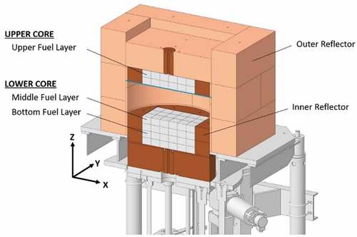
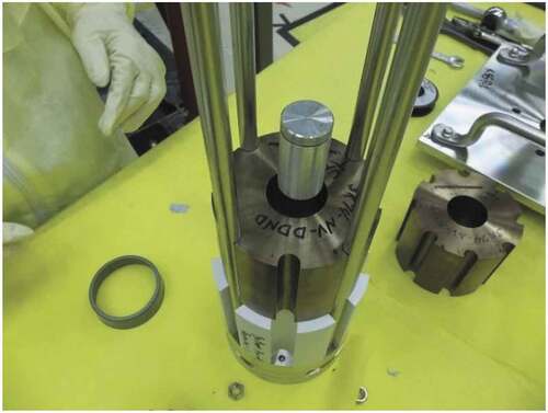
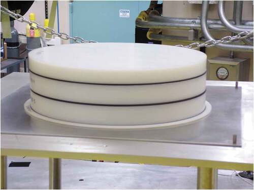
The Component Critical Experiments (Phase 1) assessed the bias in neutron multiplication due to the beryllium oxide neutron cross-section data. is a diagram of the KRUSTY experiment on the Comet assembly during the component critical measurements; is a photograph of the same. The experiment consisted of a hollow, cylindrical uranium core (93 wt% 235U, alloyed with 7.5 wt% molybdenum) weighing 32 kg with an outer diameter of 11 cm and a height of 25 cm. Eight equally spaced grooves on the periphery of the cylinder ran vertically down the length of the core. shows the core being assembled. Later, these grooves would be used to accommodate the heat pipes for the system. The system uses a single boron carbide control rod inserted in the inner hole of the reactor core. Two BeO axial reflectors were installed above and below the core, and an AmBe neutron source was placed in the center of the core to induce fission, allowing for easier measurement of neutron multiplication. The fuel, reflector, control rod, and source configuration were loaded onto Comet’s upper platform, and a radial BeO reflector was loaded onto the lower movable platen. When the platen was raised, the radial reflector would surround the core and increase the reactivity of the system. Sixty configurations were measured, changing variables such as reflector height and control rod height.Citation33
Fig. 14. Cutaway diagram of the KRUSTY experiment on the Comet assembly
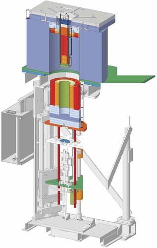
Fig. 15. Photograph of the KRUSTY experiment on the Comet assembly
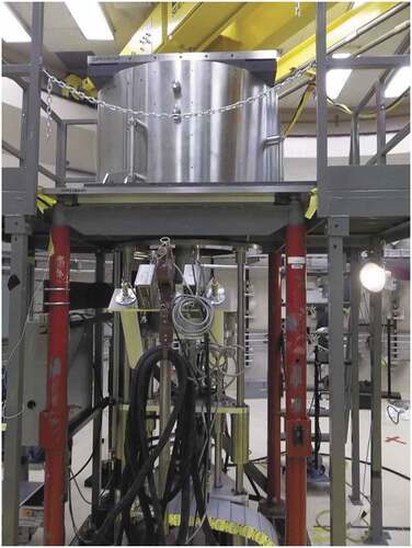
Fig. 16. Photograph of assembling the KRUSTY core
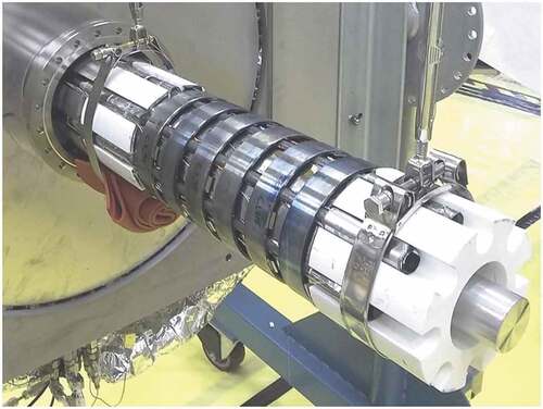
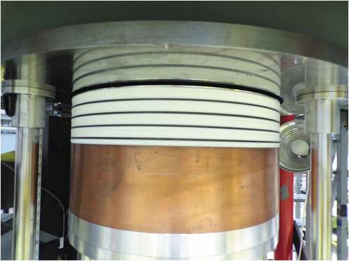
Cold Critical Experiments (Phase 2) consisted of a setup similar to Phase 1, with a few additions. To simulate the reactor’s operating environment, the core was placed in a vacuum chamber installed above the stationary platform. The eight grooves were fitted with sodium-filled heat pipes to remove heat from the core. Two of these heat pipes each ran to a Stirling engine provided by NASA. The remaining six heat pipes were connected to thermal simulators, which used liquid nitrogen to remove heat, simulating the presence of Stirling engines. is a photograph of the Stirling engines and thermal simulators. All were contained within the vacuum chamber. Using this more realistic setup, dozens of configurations of the reflector and control rod position were tested.Citation34,Citation35 shows the core of KRUSTY with heat pipes attached. The prompt neutron decay constant was also measured during this phase.Citation36
Fig. 17. Photograph of the Stirling engines and thermal simulators with the vacuum chamber removed
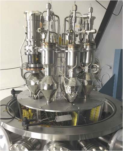
Fig. 18. Photograph of the KRUSTY core after heat pipes were attached
The Warm Critical Runs (Phase 3) included three intermediate power runs with the same vacuum chamber setup as in Phase 2 but with a single reflector configuration and no control rod. These tests determined the parameters used to model the neutronic and thermal behavior of the KRUSTY experiment. These parameters include the temperature coefficient of the fuel due to Doppler broadening of the 238U cross section and thermal expansion, an estimation of the impact of BeO cross sections, and the heat transfer coefficients between the fuel and heat pipes.Citation37
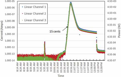
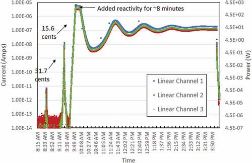
Phase 3 began with a 15 ¢ free run on March 7, 2018. The BeO reflector was inserted into a previously determined distance known to result in a 15 ¢ increase in reactivity. The system operated as designed. Initially, the power increased exponentially until the core heated, and then, excess reactivity decreased due to the negative temperature reactivity coefficient of the system. This can be seen in , which shows the response from three neutron detectors during the free run. Linear Channels 1, 2, and 3 are mounted on the wall of the building. Linear Channel 1 is located closest to Comet. This negative feedback loop decreased the power until the system was shut down. The operation resulted in a maximum power of 3.07 0.578 kW at 15 min into the run and a maximum fuel temperature of 217°C 20 min into the run.Citation37
Fig. 19. Plot of linear channel neutron detector data during 15 ¢ free run of KRUSTY experiment
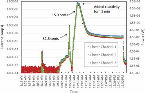
The next day, March 8, 2018, a 30 ¢ run of KRUSTY was performed on Comet. Unlike the previous run, the reactivity was not inserted all at once. A 15 ¢ free run was initiated followed by short insertions of reactivity to compensate for the temperature increases keeping the power constant at 2.5 kW. This continued until a total of 30 ¢ of reactivity had been added to the system. At that point, no additional reactivity was added, so the power began decreasing due to the increase in fuel temperature. A maximum power of 2.98 kW was reached 14 min into the run, and a maximum temperature of 288°C was reached at 32 min (CitationRef. 37). Data from this 30 ¢ run can be seen in .
Fig. 20. Plot of linear channel neutron detector data during 30 ¢ run of KRUSTY experiment
Phase 3 testing concluded with a 60 ¢ run of KRUSTY performed on March 14, 2018. Similar to the 30 ¢ run, the operation began with an immediate insertion of 15 ¢ followed by small insertions of reactivity to maintain a power level. After reaching a peak power of 3.07 kW, the power decreased to 2.5 kW. Operators continued to add reactivity for nearly 8 min until 60 ¢ had been added. At this point, system power oscillated over the next several hours due to the heating and cooling of the core. Data from this 60 ¢ run can be seen in . The peak temperature was predicted to be 447°C, and the peak recorded temperature was measured to be 446°C, well within the 10% accuracy required to allow the project to be approved to continue to the next phase.Citation37
Fig. 21. Plot of linear channel neutron detector data during 60 ¢ run of KRUSTY experiment
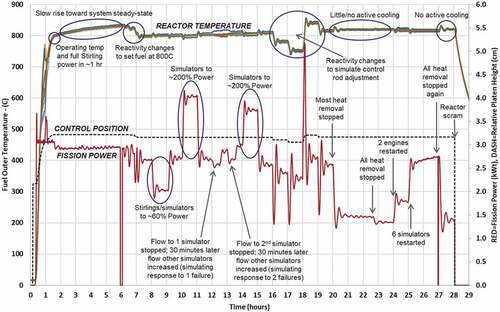
KRUSTY testing at NCERC culminated with the Nuclear System Test (Phase 4). This test investigated the nuclear-powered performance of the fully integrated KRUSTY reactor and its power conversion system. The powered run lasted 28 h and consisted of dozens of reactivity transients to test the system in its entirety.
Startup was conducted with the same 15 ¢ insertion performed during the previous phase. Once the power began to level, reactivity was gradually added to offset the increasing fuel temperature. This was done until the temperature reached 800°C (CitationRef. 38). During the 800°C measurement, a total of 1.41 $ of reactivity was added to the system, with an estimated 2.16 $ of excess reactivity available (at room temperature).
Once the temperature reached the desired level, a number of transients were introduced into the system. These included increasing and decreasing reactivity, increasing and decreasing the heat removal via the Stirling engines and thermal simulators, and even a test where the heat removal was completely turned off. During all of these tests, the reactor behaved as expected and due to negative temperature coefficients of reactivity was able to self-regulate and respond to increases or decreases in heat removal from the core. These transients, along with the reactor power and temperature responses, can be seen in .
Fig. 22. Plot of fission power and temperature data during the 28-h high-temperature run of the KRUSTY experiment
Much more detail about the KRUSTY experiment can be found in the Nuclear Technology Special Issue on the Kilopower Project, Kilowatt Reactor Using Stirling TechnologY (KRUSTY) Test published in 2020 (CitationRefs. 32, Citation33, Citation34, and Citation37–42). Five configurations from the Component Critical Experiments (Phase 1) have been evaluated as KRUSTY: “Beryllium-Oxide and Stainless-Steel Reflected Cylinder of HEU Metal,” HEU-MET-FAST-101, for submission to the ICSBEP handbook.Citation43
V.D. CURIE
In early 2020, the Critical Unresolved Region Integral Experiment (CURIE) series began on Comet. These experiments were based on the Zeus design, the primary source of validation for the 235U intermediate-energy region.Citation44 The objective of CURIE is to improve the quality of integral nuclear data in the 235U unresolved resonance region (URR).
The URR is a region within the intermediate neutron energy range (0.7 eV to 100 keV). The resonance structure in neutron cross sections is a result of the discrete energy levels of the compound nucleus, where isolated resonances are characterized by resolved resonance parameters. At some point in energy, only partially resolved structure is observed as the experimental resolution becomes comparable to the average natural width of the resonances. This transitional region, where the distinct resonance structure of the target nuclide cannot be determined empirically, is referred to as the URR.
In the ENDF/B-VIII.0 and JEFF-3.3 nuclear data libraries, the URR begins at 2.25 keV and continues until 25 keV (CitationRefs. 45 and Citation46). In this energy regime, resonances are so close to one another that the structure cannot be determined empirically. At present, there are only a small number of intermediate neutron energy benchmarks available in the ICSBEP for 235U, and there are none that are highly sensitive to the URR. CURIE not only is the first integral experiment with optimized sensitivity to the 235U URR but also is the first time the Los Alamos Critical Experiments Team utilized a machine learning approach to design an integral experiment.
Designing a critical experiment in this energy regime is difficult, as fast neutrons from fission must be slowed down to intermediate energies, but not too much or they will reach thermal energies. To accomplish this, experimenters used alternating thick layers of Teflon (C2F4) and the HEU Jemima plates surrounded by the Zeus copper reflector. The combination of fuel and reflector makes this experiment a valuable extension of the Zeus series. shows the lower portion of the core of the CURIE experiment. The thicknesses of Teflon were carefully chosen to both bound and span the URR. They range from 5/8 to 9/8 in. While the changes in thickness between each of the five configurations are small, preliminary results show they have significant differences in sensitivities, thus pointing to successful optimization. Rossi-alpha measurements were also taken for three of the configurations, helping to better understand the neutron spectrum across the range of configurations. These supplemental measurements are an essential part of the overall data sets. Despite operational slowdowns due to COVID-19, measurements for this experiment concluded in the summer of 2020 (CitationRef. 47). Evaluation of the CURIE benchmark is in progress, and results will be published in the ICSBEP handbook when complete.
Fig. 23. Photograph of a portion of the CURIE experiment on Comet
The results of the CURIE experiment not only will provide improvements in nuclear data but also because of their sensitivity to the URR will provide improvements and validation to neutron transport codes. The codes use varying approaches to address the URR, and all have some level of approximation. As computations become increasingly detailed and advanced, the codes use fewer and fewer approximations. These changes lead to results that are unvalidated. CURIE provides validation to the new code methodologies that cannot be achieved without an experiment specifically sensitive to the URR.
V.E. Thermal/Epithermal Experiments
Thermal/Epithermal eXperiments(TEX) is a series of critical experiments at NCERC designed and executed as a collaboration between LANL and Lawrence Livermore National Laboratory. The TEX experiments address nuclear data and validation needs for the criticality safety and nuclear data communities by creating critical experiments that span a wide range of fission energies, from thermal to fast.
The TEX-HEU measurements used the Jemima plates with various thicknesses of polyethylene moderators to create a baseline set of critical configurations.Citation48 By using different thicknesses of polyethylene moderators, the neutron energy spectrum of the experiment changes from fast to thermal, including some mixed or intermediate-energy spectra configurations. The thermal and fast configurations are expected to closely match calculated predictions, as the underlying nuclear data in these areas are extensively measured, with relatively simplistic data structure, and well validated with integral experiments. Larger deviations from predictions are expected for the intermediate and mixed configurations, which have underlying data that are less well understood. These baseline configurations were designed to later incorporate additional materials of interest (diluents) to generate integral benchmarks.
Five configurations were chosen to produce unique neutron fission spectra. The baseline TEX-HEU experiments consist of five configurations with varying amounts of polyethylene moderator between each Jemima plate, ranging from 0 in. of polyethylene to 1.5 in. of polyethylene. shows an example of a TEX-HEU experiment with polyethylene moderators. A 1-in. polyethylene reflector surrounded the stack of Jemima plate–polyethylene units.
Fig. 24. Photograph of the upper portion of the TEX-HEU experiment on Comet with outer reflector removed
The baseline TEX-HEU experiments were performed on Comet from February to June of 2020. Similar to CURIE, these experiments were conducted despite operational slowdowns due to COVID-19. An additional camera system was installed by NCERC personnel to allow observers in the control room to see the crew assembling the bare fuel. During high-power operations, the cameras were removed; however, during low-power operations, the cameras were left in place, and photographs of the display such as were taken. Benchmark evaluations of the TEX-HEU baseline experiments are expected to be submitted to ICSBEP in Fall 2021. Future TEX-HEU configurations that include hafnium (Hf), chlorine, lithium, and other materials of interest to the nuclear data or criticality safety communities are planned and will be compared to the baseline configurations.
Fig. 25. Photograph of the TEX-HEU experiment on Comet viewed over new camera system
VI. CONCLUSION AND FUTURE WORK
The Comet vertical-lift machine has a long history of versatility that has provided useful data for many purposes. After moving from TA-18 to NCERC, Comet has continued to play a role in the successful production of useful data for ICSBEP benchmarks, proof-of-concept testing for new reactor designs, and computational validation. The near-infinite experimental possibilities provided by the machine will continue to be vital, and further experiments are being planned for execution in the near future.
Future work includes the TEX-HEU-Hf experiment and a critical experiment currently being designed to test copper cross sections. Both are planned to be evaluated as ICSBEP benchmarks. Adapters have also been constructed and tested to perform the Class Foils experiment on Comet when Planet is being utilized for another experiment. Last, an experiment under the Experiments Underpinned by Computational Learning for Improvements in nuclear Data (EUCLID) Laboratory Directed Research and Development program may be executed on Comet, with the goal of quick turnaround on improvements to nuclear data and into users’ hands.Citation49,Citation50
Acknowledgments
This work was supported by the U.S. Department of Energy (DOE) Nuclear Criticality Safety Program (NCSP), funded and managed by NNSA for the DOE.
This work was supported by the DOE through LANL. Los Alamos National Laboratory is operated by Triad National Security, LLC, for NNSA of the DOE under contract number 89233218CNA000001.
Work detailed within this document was performed with the support of many sponsors including the NCSP, Nuclear Counter-Terrorism, Defense Nuclear Nonproliferation, NASA, and others.
The authors would like to thank all involved in the success of these measurements (including all logistics to perform measurements in a nuclear facility). We would like to specifically thank the following individuals for their significant contributions to Comet operations in the past 10 years: Timothy Beller, John Bounds, Timothy Dugan, James Dyson, Jeffrey Favorite, Masahiro Fukushima, Steve Klein, Hiroki Iwamoto, Michael James, Donnette Lewis, Jessica Lillo, Michelle Loyd, Patrick McClure, Alex Lynn, Ryan LeCounte, Justin Martin, Ross Matzkin-Bridger, Tony Nelson, Kenji Nishihara, Jesse Norris, Akito Oizumi, Martin Parrales, Catherine Percher, Eloura Phelps, Daniel Perlstein, Dave Poston, Chris Romero, Eric Sorenson, Kazufumi Tsujimoto, Nicholas Wynne, Kenneth Valdez, and Mission Support and Test Services/National Security Technologies operations.
References
- D. LOAIZA and D. GEHMAN, “End of an Era for the Los Alamos Critical Experiments Facility: History of Critical Assemblies and Experiments,” LA-14306-H, Los Alamos National Laboratory (2006).
- G. A. JARVIS and C. B. MILLS, “Critical Mass Reduction,” LA-3651, Los Alamos National Laboratory (1967).
- R. SANCHEZ et al., “Comet Startup at NCERC and Acquisition of New Data,” LA-UR-12-01161, Los Alamos National Laboratory (2012).
- H. C. PAXTON, “Thirty Years at Pajarito Canyon Site,” LA-7121-H, Rev. 1, Los Alamos National Laboratory (1981).
- H. C. PAXTON, “A History of Critical Experiments at Pajarito Site,” LA-9685-H, Los Alamos National Laboratory (1983).
- R. E. MALENFANT, “Los Alamos Critical Experiments Facility,” LA-8762-MS, Rev. 1, Los Alamos National Laboratory (1981).
- J. HUTCHINSON et al., “A New Era of Nuclear Criticality Experiments, the First Ten Years of Radiation Test Object Operations at NCERC,” Nucl. Sci. Eng., 195, S80 (2021); https://doi.org/10.1080/00295639.2021.1918938.
- R. E. MALENFANT, “Little Boy Replication: Justification and Construction,” LA-UR-83-3520, Los Alamos National Laboratory ( 1983).
- H. A. ROBITAILLE and B. E. HOFFARTH, “Neutron Leakage from ‘COMET’—A Duplicate Little-Boy Device,” Report 878, Defence Research and Development Canada (1983).
- R. MOSTELLER, R. BREWER, and J. SAPIR, “The Initial Set of Zeus Experiments: Intermediate-Spectrum Critical Assemblies with a Graphite-HEU Core Surrounded by a Copper Reflector,” International Handbook of Evaluated Criticality Safety Benchmark Experiments, Organisation for Economic Co-operation and Development Nuclear Energy Agency (2016); https://doi.org/10.1787/e2703cd5-en (NEA;7328).
- D. HAYES, “Zeus: Fast-Spectrum Critical Assemblies with an Iron-HEU Core Surrounded by a Copper Reflector,” International Handbook of Evaluated Criticality Safety Benchmark Experiments, Organisation for Economic Co-operation and Development Nuclear Energy Agency, Paris (2016); https://doi.org/10.1787/e2703cd5-en (NEA;7328).
- R. MOSTELLER, “The Unmoderated Zeus Experiment: A Cylindrical HEU Core Surrounded by a Copper Reflector,” International Handbook of Evaluated Criticality Safety Benchmark Experiments, Organisation for Economic Co-operation and Development Nuclear Energy Agency, Paris (2016); https://doi.org/10.1787/e2703cd5-en (NEA;7328).
- T. CUTLER et al., “The Zeus Assembly on Comet: Past, Present, and Future Benchmarks,” Trans. Am. Nucl. Soc., 119, 1, 826 (2018).
- K. JACKMAN et al., “Radiochemistry Results from the IER-163 COMET Irradiation,” LA-UR-12-20256, Los Alamos National Laboratory (2015); https://doi.org/10.2172/1038120.
- R. SANCHEZ et al., “Reaction Rate, Fission Product Yield, and Rossi-α Measurements Using a HEU Metal, Copper Reflected Critical Assembly,” J. Nucl. Sci. Technol., 52, 7–8, 1018 (2015); https://doi.org/10.1080/00223131.2015.1027157.
- G. McKENZIE et al., “Prompt Neutron Decay Constants in a Highly Enriched Uranium Copper Reflected System,” Trans. Am. Nucl. Soc., 110, 1, 303 (2014).
- “International Handbook of Evaluated Criticality Safety Benchmark Experiments,” NEA 7497, Organisation for Economic Co-operation and Development Nuclear Energy Agency (2019).
- M. FUKUSHIMA et al., “Lead Void Reactivity Worth in Two Critical Assembly Cores with Differing Uranium Enrichments,” Nucl. Sci. Eng., 189, 1, 93 (2018); https://doi.org/10.1080/00295639.2017.1373520.
- N. THOMPSON, R. BAHRAN, and J. HUTCHINSON, “Identifying Gaps in Critical Benchmarks,” Trans. Am. Nucl. Soc., 119, 1, 829 (2018).
- M. FUKUSHIMA et al., “Lead Void Reactivity Worth in Two Critical Assembly Cores with Differing Uranium Enrichments,” Nucl. Sci. Eng., 189, 1, 93 (2018); https://doi.org/10.1080/00295639.2017.1373520.
- M. FUKUSHIMA et al., “Systematic Measurements and Analyses for Lead Void Reactivity Worth in a Plutonium Core and Two Uranium Cores with Different Enrichments,” Nucl. Sci. Eng., 194, 2, 138 (2019); https://doi.org/10.1080/00295639.2019.1663089.
- J. GODA, T. GROVE, and G. McKENZIE, “Improvements in Void Reactivity Worth Measurements Using a Load Cell as Pressure Sensor,” Proc. 11th Int. Conf. Nuclear Criticality Safety (ICNC 2019), Paris, France, September 15–20, 2019.
- J. GODA et al., “Void Reactivity Worth in Uranium/Lead Systems,” Proc. PHYSOR 2015, Sun Valley, Idaho, May 1–5, 2015.
- N. THOMPSON et al., “National Criticality Experiments Research Center (NCERC)— Capabilities and Recent Measurements,” EPJ Web Conf., 239, 18003 (2020); https://doi.org/10.1051/epjconf/202023918003.
- A. McSPADEN et al., “Update on the Benchmark Analysis of the Jupiter Experiments: Plutonium Moderated by Lead,” Trans. Am. Nucl. Soc., 123, 1, 824 (2020); https://doi.org/10.13182/T123-33172.
- K. AMUNDSON et al., “Fast-Spectrum Critical Assemblies with a Pb-HEU Core Surrounded by a Copper Reflector,” Trans. Am. Nucl. Soc., 123, 1, 817 (2020); https://doi.org/10.13182/T123-32885.
- R. SANCHEZ et al., “Prompt Neutron Decay Constants in a Highly Enriched Uranium-Lead Copper Reflected System,” Trans. Am. Nucl. Soc., 115 (2016).
- R. LELL et al., “ZPPR-21 Phase A: A Cylindrical Assembly of Pu Metal Reflected by Graphite,” International Handbook of Evaluated Criticality Safety Benchmark Experiments, Organisation for Economic Co-operation and Development Nuclear Energy Agency, Paris (2016); https://doi.org/10.1787/e2703cd5-en (NEA;7328).
- R. LELL et al., “ZPR-6 Assembly 10: A Cylindrical Plutonium/Carbon/Stainless Steel Assembly with Stainless Steel and Iron Reflectors,” International Handbook of Evaluated Criticality Safety Benchmark Experiments, Organisation for Economic Co-operation and Development Nuclear Energy Agency, Paris (2016); https://doi.org/10.1787/e2703cd5-en (NEA;7328).
- R. LELL, “ZPR-3 Assembly 59: A Cylindrical Assembly of Plutonium Metal and Graphite with a Thick Lead Reflector,” International Handbook of Evaluated Criticality Safety Benchmark Experiments, Organisation for Economic Co-operation and Development Nuclear Energy Agency, Paris (2016); https://doi.org/10.1787/e2703cd5-en (NEA;7328).
- J. GODA et al., “Comparison of Methods for Determining Multiplication in Subcritical Configuations of a Plutonium System,” Proc. PHYSOR 2018, Cancun, Mexico, April 22–26, 2018.
- P. R. McCLURE et al., “Kilopower Project: The KRUSTY Fission Power Experiment and Potential Missions,” Nucl. Technol., 206, Suppl. 1, S1 (2020); https://doi.org/10.1080/00295450.2020.1722554.
- R. SANCHEZ et al., “Kilowatt Reactor Using Stirling TechnologY (KRUSTY) Component—Critical Experiments,” Nucl. Technol., 206, Suppl. 1, S56 (2020); https://doi.org/10.1080/00295450.2020.1722553.
- T. GROVE et al., “Kilowatt Reactor Using Stirling TechnologY (KRUSTY) Cold Critical Measurements,” Nucl. Technol., 206, Suppl. 1, S68 (2020); https://doi.org/10.1080/00295450.2020.1712950.
- K. STOLTE et al., “Neutronics Analysis of Cold Critical KRUSTY Experiments Using MCNP and Serpent,” Trans. Am. Nucl. Soc., 122, 1, 657 (2020); https://doi.org/10.13182/T122-32642.
- G. McKENZIE et al., “Prompt Neutron Decay Constant Measurements on the KRUSTY Cold Critical Configuration,” Trans. Am. Nucl. Soc., 119, 1, 822 (2018).
- D. POSTON et al., “Results of the KRUSTY Warm Critical Experiments,” Nucl. Technol., 206, Suppl. 1, S78 (2020); https://doi.org/10.1080/00295450.2020.1727287.
- D. POSTON et al., “Results of the KRUSTY Nuclear System Test,” Nucl. Technol., 206, Suppl. 1, S89 (2020); https://doi.org/10.1080/00295450.2020.1730673.
- P. R. McCLURE, “Foreword: Special Issue on the Kilopower Project, Kilowatt Reactor Using Stirling TechnologY (KRUSTY) Test,” Nucl. Technol., 206, Suppl. 1, iii (2020); https://doi.org/10.1080/00295450.2020.1737486.
- D. I. POSTON et al., “KRUSTY Reactor Design,” Nucl. Technol., 206, Suppl. 1, S13 (2020); https://doi.org/10.1080/00295450.2020.1725382.
- M. A. GIBSON et al., “Heat Transport and Power Conversion of the Kilopower Reactor Test,” Nucl. Technol., 206, Suppl. 1, S31 (2020); https://doi.org/10.1080/00295450.2019.1709364.
- P. R. McCLURE et al., “KRUSTY Experiment: Reactivity Insertion Accident Analysis,” Nucl. Technol., 206, Suppl. 1, S43 (2020); https://doi.org/10.1080/00295450.2020.1722544.
- J. A. FAVORITE et al., “Status of the KRUSTY Benchmark Modeling and Uncertainty Analysis,” Trans. Am. Nucl. Soc., 123, 1, 813 (2020); https://doi.org/10.13182/T123-32876.
- T. CUTLER et al., “CURIE Preliminary Design,” Trans. Am. Nucl. Soc., 119, 1, 728 (2018).
- D. BROWN et al., “ENDF/B-VIII.0: The 8th Major Release of the Nuclear Reaction Data Library with CIELO-Project Cross Sections, New Standards and Thermal Scattering Data,” Nucl. Data Sheets, 148, 1 (2018); https://doi.org/10.1016/j.nds.2018.02.001.
- A. J. M. PLOMPEN et al., “The Joint Evaluated Fission and Fusion Nuclear Data Library, JEFF-3.3,” Eur. Phys. J. A, 56, 181 (2020).
- T. CUTLER et al., “Critical Unresolved Region Integral Experiment Execution,” Trans. Am. Nucl. Soc., 123, 1, 828 (2020); https://doi.org/10.13182/T123-33364.
- J. NORRIS et al., “TEX-HEU: Integral Experiment Execution of Thermal/Epithermal eXperiments Using Highly Enriched Uranium with Polyethylene, IER-297 CED-3b Report,” LLNL-TR-817959, Lawrence Livermore National Laboratory (2020).
- I. MICHAUD et al. “Designing Critical Experiments Using Gaussian Process Optimization,” Trans. Am. Nucl. Soc., 121, 1035 (2019); https://doi.org/10.13182/T31031.
- N. KLEEDTKE et al., “Gaussian Process Optimization of Sensitivity-Based Similarity Metrics Between New Nuclear Applications and New/Existing Benchmarks,” Trans. Am. Nucl. Soc., 123, 837 (2020); https://doi.org/10.13182/T123-33071.