
 ?Mathematical formulae have been encoded as MathML and are displayed in this HTML version using MathJax in order to improve their display. Uncheck the box to turn MathJax off. This feature requires Javascript. Click on a formula to zoom.
Abstract
This study assesses a Rotational Fuel-Shuffling Breed-and-Burn (RFBB) fast reactor that operates in breed-and-burn (B&B) mode with a rotational fuel-shuffling scheme and remains within the 200 displacements per atom (DPA) radiation damage constraint of currently verified cladding materials. The design is based on a commercial-scale fast burner reactor called the Super Power Reactor Innovative Small Module (S-PRISM) reactor. To reduce the high DPA values of discharged fuels, the melt-refining process developed in the Experimental Breeder Reactor-II (EBR-II) project is adopted in this study. The effects of the melt-refining process on the performance of the RFBB are investigated via five scenarios and compared with a core to which the melt-refining process is not applied: Scenario I, “Homogenization,” occurs without the removal of fission products (FPs) during the melt-refining process; Scenario II, “Homogenization and FP Removal,” occurs with the removal of FPs to a fraction similar to that in the melt-refining process developed in the EBR-II project; Scenario III, “Homogenization, FP Removal, and Make-Up,” is similar to Scenario II but makes up fuel losses with natural uranium; Scenario IV, “With 1% TRU [transuranics] Losses,” is similar to Scenario III but is evaluated with 1% of actinides not recovered; Scenario V, “With 10% TRU Losses,” is similar to Scenario III but is evaluated with 10% of actinides not recovered. The results show that it is neutronically and thermal hydraulically feasible to establish a B&B mode with the rotational fuel-shuffling scheme and by reconditioning the fuel whenever its cladding reaches its proven 200 DPA radiation damage limit. In Scenario V, the core is subcritical due to a large number of actinides not being recovered during the melt-refining process. The cores of the other scenarios are all critical. The cores of scenarios in which FPs are removed during the melt-refining process have higher excess reactivity than that of the core of Scenario I (“Homogenization”) and that of the core to which the melt-refining process is not applied. The numerical analyses also show that in scenarios that include making up fuel losses during melt refining, the core is fed with more natural uranium make-up fuel during operation and thus has lower burnup. Other characteristics, such as power density distributions, neutron flux profiles, and fertile and fissile nuclide density distributions, are all stable during operation.
I. INTRODUCTION
Natural uranium contains 0.72 wt% of the fissile isotope 235U. Present-day light water reactors (LWRs) are usually fed 3 to 5 wt% enriched 235U. Most current LWRs utilize about 0.6% natural uranium. However, it may be possible to enhance uranium utilization using a special class of fast reactors with the breed-and-burn (B&B) mode of operation, referred to as B&B reactors. As the result of previous study,Citation1 it is neutronically feasible to establish a B&B mode of operation in a fast reactor that can be safely operated up to an average burnup of at least ~20% fissions per initial metal atom (FIMA), and the uranium utilization of such B&B reactors is ~40 times that of LWRs. The B&B mode of operation, first proposed by Feinberg in 1958 (CitationRef. 2), is made self-sustainable by producing fissile materials such as 239Pu (or 233Pu) from fertile materials such as 238U (or 232Th) during operation. In a B&B reactor, the fissile elements are first bred into the fuel by neutrons produced in the reactor. The resulting bred fuel is then directly burned in the same reactor to sustain the chain reaction and to supply neutrons for breeding additional fuel. Thereafter, the B&B core is able to continue operating while being fed with depleted or natural uranium only. Therefore, B&B reactors can operate using primarily fertile fuel but also reload fuel, such as natural or depleted uranium, low-enriched uranium, used LWR fuel, or thorium.
Breed-and-burn reactors have been intensively studied as well at the University of California, Berkeley (UCB), in Project No. 09-769 (CitationRef. 1) and Project No. 12-3486 (CitationRef. 3); at the Tokyo Institute of Technology with the CANDLE burning fast reactorCitation4; and at TerraPower with the TerraPower Traveling Wave reactor.Citation5 Unlike the cores in other classes of fast reactors, B&B reactors can operate with loading fuel of fertile materials with natural content. Therefore, B&B reactors require high neutron economy to maintain criticality in operation. The feed fuel must be burned to a sufficient level such that the rate of neutron production increases with burnup and overtakes that of neutron absorption in operation. That is, the generated neutrons are equal (or slightly larger) than the total number of neutrons lost, i.e., lost to absorption and also leakage for sustaining the chain reaction that can contribute to the B&B reactor.
To improve neutron economy and achieve both criticality with the B&B mode of operation and a stable power profile in the core, the Rotational Fuel-Shuffling Breed-and-Burn (RFBB) fast reactor has been proposed by a research group at the Tokyo Institute of Technology.Citation6,Citation7 In this fuel-shuffling concept, fresh fuel is loaded from the periphery of the core and eventually moves toward the center. The fuel moves outward and is then discharged near the periphery of the core. As a result, the B&B region remains stationary, and the power profile and neutron flux distribution are thereby almost unchanged during operation in the equilibrium state. In RFBB operation, the high-reactivity fuels are located at the core center, which is the high-neutron-importance region.
A previous study shows that it is feasible to establish the B&B mode of operation with rotational fuel shuffling in the Super Power Reactor Innovative Small Module (S-PRISM) reactor core based on neutronic and thermal-hydraulic analyses.Citation8 The S-PRISM core design is well known as a reference design for a detailed and practical advanced reactor system design. The S-PRISM core design was developed by General ElectricCitation9 and chosen as a reference core in other projects such as Project No. 09-769 (CitationRef. 1) and Project No. 12-3486 (CitationRef. 3) performed at the UCB.
The previous studyCitation8 demonstrated the feasibility of applying the rotational fuel-shuffling concept to a viable reactor design that is based on the S-PRISM core and/or that could fit within the S-PRISM reactor vessel developed by General Electric. To achieve criticality in the B&B strategy, the core height has been increased from the reference 101.6 to 200 cm, and the pitch-to-diameter (P/D) ratio has been decreased from the reference 1.191 to 1.086. In addition, the core has used the binary metallic fuel U-Zr with 2 wt% zirconium.Citation8 As a consequence, the core generates 400 MW(thermal) of power with the rotational fuel-shuffling scheme. The shuffling interval is 1125 to 1250 days, and the possible axial average discharged burnup is from 274.8 to 305.3 GWd/tonne HM. The reference S-PRISM core power level is 1000 MW(thermal) whereas the RFBB core in this study has a power level of 400 MW(thermal). This difference is due to the significantly higher ratio of core average to peak power density of the reference S-PRISM core, and it ensures that the design of the RFBB core would meet the design constraints as in the previous study.Citation8
However, because of the long fuel cycle length (FCL) and long resident time of fuel in the core during operation, its fuel cladding would reach radiation damage of nearly 2900 displacements per atom (DPA). So far, the maximum radiation damage that cladding and structural materials have been exposed to is approximately 200 DPA of radiation damage, which occurred in a test at the Fast Flux Test Facility.Citation10 Therefore, high DPA radiation damage from the discharged fuels must be considered in the development of a more practical and realistic design.
As mentioned in CitationRef. 8, this issue of high DPA radiation damage could be overcome by either of two promising approaches: One is to shorten the operational time and to reclad the fuel cladding, and the other is to apply a melt-refining process similar to the one experimented with during the Experimental Breeder Reactor-II (EBR-II) project for fuel reconditioning. In comparison with the first approach, the second not only improves burnup with fuel reconditioning but also is attractive in terms of proliferation concerns. The melt-refining process, which is also suitable for metallic fuel, is a proven strategy, having been successfully used at Argonne National Laboratory to recycle EBR-II fuel.Citation11,Citation12 This melt-refining process has also been selected in other B&B reactor studies to perform fuel reconditioning when cladding reaches the maximum radiation damage.Citation13,Citation14 The purposes of the present study are to clarify the effects of the melt-refining process on the performance of sodium-cooled B&B reactors with a rotational fuel-shuffling scheme, called rotational fuel-shuffling B&B fast reactors with metal fuel and sodium coolant (RFBB-MS), and to address the fuel cladding integrity issue due to radiation displacement damage and to maintain fuel element integrity under a high-burnup condition.
II. METHODOLOGY
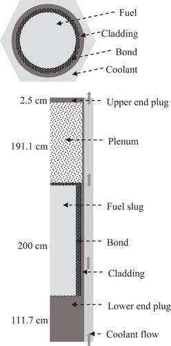
II.A. Reactor Concept
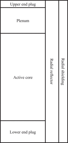
The RFBB studied in this paper is conceptually similar to the core in the previous workCitation8 and to the S-PRISM core design by General ElectricCitation9 and by Argonne National Laboratory in their recent studies of the Advanced Burner Reactor (ABR) (CitationRefs. 15 and Citation16). It is sodium cooled and uses the binary metallic fuel U-Zr with 2 wt% zirconium. The initially unirradiated fuel nominal density is 17.8 g/cmCitation3 (CitationRef. 17), and a smear factor of 0.75 is assumed to accommodate the fuel swelling with burnup. To maintain criticality in the B&B mode of operation of a reactor with the same core radius as the S-PRISM core, the original core layout is modified; that is, fuel assemblies replace the 12 control assemblies and 6 gas expansion modules, and the fuel assembly at the core center is filled with coolant. As a result of this modification, the metal-fueled core layout in this study is composed of 252 fuel assemblies, 1 coolant channel, 126 reflector assemblies, and 72 shield assemblies.Citation8 The cladding material is the ferritic-martensitic alloy HT-9. The core height is increased from the reference of the S-PRISM core, 101.6 to 200 cm, and the P/D ratio is decreased from the reference, 1.191 to 1.086 (CitationRef. 8). The core layout is presented in . The active core is surrounded by two layers of radial assembly reflectors and one radial assembly shielding layer, and its composition is as those of the metallic fuel version of the S-PRISM core developed by General Electric.Citation9,Citation16,Citation18
Fig. 1. Simplified layout of the B&B core and surrounding regions.
II.B. Melt-Refining Process
To keep the fuel cycle as proliferation resistant as possible, and considering that actinide separation is undesirable, the melt-refining process was developed for metallic fuel during the EBR-II project.Citation19 This fuel-reconditioning process involves several operations, including disassembly of the reactor core subassemblies, decladding, melt-refining proper, refabrication (injection casting), canning and bonding, and reassembly of reactor core subassemblies. During this melt-refining process, the fuels undergo several stages. It is cooled for a sufficient period of time after the reactor is shut down and then transferred to the processing plant, after which the fuel-pin cladding is cut at opposite sides of the pin by roll cutters so that the cladding is left over the fuel pin. The fuel pin is then chopped to the appropriate length before being reconditioned in the melt-refining stage.Citation19
In the melt-refining stage, the fuels are decladded and melted at about 1300°C for several hours under a high-purity argon atmosphere. The volatile fission elements evaporate, and the reactive fission elements are removed by oxidation with the zirconia of the crucible. According to a previous report,Citation19 this process can remove nearly 100% of Br, Kr, Rb, Cd, I, Xe, and Cs and at least 95% of Sr, Y, Te, Ba, and rare earths (lanthanides). Thorium and americium are also oxidized with zirconia, and 95% of thorium and americium is removed from the fuel. A small fraction of other actinides would also be left in the crucible. The refined fuel obtained by melt refining is then processed in the first step of new fuel refabrication, referred to as injection casting of new fuel pins. The purpose is to convert the bulk fuel feed material into sound cylindrical castings, called fuel slugs, of proper lengths to produce long fuel pins refabricated with a new clad. The new fuel pins are fabricated into new fuel assemblies that can then be reloaded into the core for a new burnup cycle. It is therefore that the rotational fuel-shuffling scheme associated with the melt-refining process could provide a good measure of alleviating proliferation concerns. In addition, it is feasible to use natural uranium only to operate the B&B reactor and to reduce the waste disposal burden and radiotoxicity in its spent fuels as well.
In the melt-refining process experimented with in the EBR-II program, several percent of the plutonium and other actinides remains in the crud of the zirconia crucible. In order to investigate the effects of the fraction fission products (FPs) that are removed or lost in the fuel recycling process, this study considers the significant loss of TRU due to the melt-refining process; it is assumed that 1% and 10% of all actinides are not recovered, as shown in (CitationRef. 1).
TABLE I Actinides and FP Removal Fractions in the Melt-Refining Process
II.C. Calculation Method
The numerical core simulation is done using the Monte Carlo Serpent neutronic codeCitation20 with the ENDF-B/VII nuclear data library.Citation21 Five thousand neutron histories per cycle and 200 active cycles, while skipping the first 20 cycles for statistical treatment, are used to obtain a target statistical error in keff of ~150 pcm. The burnup calculation is carried out for a symmetrical one-sixth core region in the azimuthal direction. The axial direction is symmetrically divided into 11 burnup regions as in the previous study.Citation8 In the present study, we focus on the burnup performance of the reactor in the equilibrium state. The period of time in which fuel assemblies are either removed from or added to the core is defined as one FCL. The averaged fuel burnup in the equilibrium state is defined as follows:
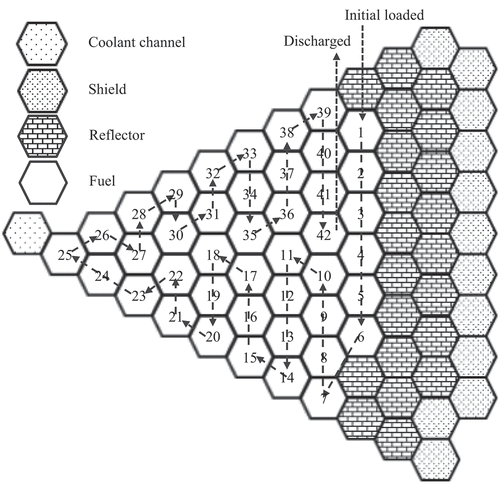
The shuffling scheme discussed in this section is the rotational fuel-shuffling scheme as schematized in . In this figure, each fuel assembly position is assigned a position identification number (ID), and the fuel-shuffling flow is from fuel assembly position IDs 1 to 42. In this rotational fuel-shuffling scheme, a fresh fuel assembly is loaded at position 1. The fuel assembly is moved inward after the first 25 fuel-shuffling steps (from 1 to 25), then moved outward, and discharged after 17 fuel-shuffling steps, at position 42.
Fig. 2. Fuel cell model for thermal-hydraulic analyses.
The burnup analysis is performed assuming that recycling takes place when the radiation damage of the clad (that is, the fluence of neutrons with energy exceeding 0.1 MeV) approaches 200 DPA. At that time, natural uranium is added to the fuel to make up for the gaseous and volatile FPs and/or losses of fuel that got out during the melt-refining process. To achieve the equilibrium state of the B&B reactor, a computer interface program was previously developed to automatically conduct core burnup calculations from cycle to cycle. In this study, the first core is loaded with the fuel of natural uranium. The real startup core needs fissile material. To design the startup core is one of the future works, which are in progress. The calculation procedure is performed as followsCitation8:
Design parameters such as core size, fuel assemblies, fuel-shuffling pattern, operational conditions, and FCL are prepared in the input file.
The core burnup calculation is performed to obtain end-of-cycle fuel compositions.
The melt-refining operation is performed for the selected fuel assemblies whose maximum value of radiation damage of the fuel clads approaches 200 DPA.
The input file is updated with the new fuel compositions obtained in step 3, along with the fuel-shuffling pattern. The core burnup calculation for the next cycle is performed using the new input file.
Steps 2 and 4 are repeated until the core reaches an equilibrium condition, as determined based on the convergence of the keff, neutron flux distribution, power density distribution, and nuclide number density values of some isotopes such as 239Pu, 241Pu, 235U, and 238U.
Thermal-hydraulic analyses are conducted in the steady-state regime to make sure that the core design obeys a number of constraints such as core inlet and outlet temperatures, core pressure drop, maximal core coolant velocity, peak cladding temperature, and peak fuel temperature. In thermal-hydraulic analyses, the hottest subchannel in the core is chosen for thermal-hydraulic analysis to determine whether or not the reactor satisfies the desired design constraints. The thermal-hydraulic analysis is performed using COMSOL 5.4 multiphysics software.Citation22 The geometry model is developed with two-dimensional axisymmetry with R-Z coordinates consisting of the fuel slug, bond layer, cladding, coolant channel, lower end plug, plenum, and upper end plug, as in CitationRefs. 8, Citation23, Citation24, and Citation25. The model geometry of the subchannel analysis for the whole length of the reactor is provided, as can be seen in . The hexagonal cell lattice is simplified so that it is equivalent to a cylinder. This cell lattice model is the hottest channel of a fuel pin in the core. The sodium coolant flows vertically upward through the cooling channel. In the thermal-hydraulic analysis, the power distribution of the fuel rod in the axial direction is obtained from the neutronic analysis.
Fig. 3. The fuel-shuffling pattern and position IDs of fuel assemblies in the core. In this rotational fuel-shuffling scheme, a fresh fuel assembly is loaded at position 1. The fuel assembly is moved inward after the first 25 fuel-shuffling steps (from positions 1 to 25) and then moved outward and discharged after 17 fuel-shuffling steps at position 42.
In this study, the core investigated in the previous workCitation8 is chosen as the reference core, called “Reference.” The core height is 200 cm, and the P/D ratio is 1.086. The core uses the binary metallic fuel U-Zr with 2 wt% zirconium. In previous analyses, the core generated 400 MW(thermal) in a rotational fuel-shuffling scheme with a shuffling interval, i.e., FCL, of 1125 days and a possible average discharged burnup of 274.8 GWd/tonne HM. The effects of the melt-refining process on the performance of the RFBB are investigated under five scenarios and compared with the Reference scenario in which the melt-refining process is not applied to the core. These five scenarios are as follows:
Scenario I, “Homogenization,” involves only fuel homogenization and without the removal of FPs during the melt-refining process. This is because the fuels are mixed during the melt-refining stage at about 1300°C for several hours under a high-purity argon atmosphere. As a consequence, the burnup characteristics can be affected by mixed-only fuel during the melt-refining stage of the melt-refining process.
Scenario II, “Homogenization and FP Removal,” involves homogenization with the removal of fission products with the similar fraction of the melt-refining process developed in the EBR-II project. In this scenario, the removal of fission products as in the original melt-refining process developed in the EBR-II project is considered to understand its effects on the burnup characteristics of the core.
Scenario III, “Homogenization, FP Removal, and Make-Up,” is similar to Scenario II, but natural uranium compensates for the FP losses by burnup and fission product removals during the melt-refining process to conserve the unchanged fuel amount in the fuel pins.
Scenario IV, “With 1% TRU Losses,” is similar to Scenario III but is evaluated with 1% of all actinides not recovered.
Scenario V, “With 10% TRU Losses,” is similar to Scenario III but is evaluated with 10% of all actinides not recovered.
Scenarios IV and V are investigated because as reported previously,Citation19 at the melt-refining stage at maximum charge (~11 kg/cycle), ~10% of the melt remains as skull and a larger fraction remains at smaller charges. To investigate the effects of the fraction and type of solid FPs removed in the fuel recycling process, this study considers significant losses (1% and 10%) of actinides as not recovered due to the melt-refining process, as shown in (CitationRef. 2).
For upper-bound estimation, fuel shuffling is assumed to be instantaneous. Regarding the cooling fuel during the melt-refining process, two cooling intervals are considered. Cooling intervals are taken into account before the melt-refining process (Tc) and after the melt-refining process (Tw). In this study, the cooling time Tc taken before the melt-refining process is conservatively assumed to be 9.125 days (i.e, 2.5 years). The latter cooling time Tw taken after the melt-refining process thereby is equal to (1 FCL – Tc). The changes in nuclide densities during the cooling time periods are calculated considering the radioactive decay of nuclides using an in-house program written in Python script specifically designed to obtain these nuclide densities as in our previous studies.Citation23,Citation24 It is possible to operate the core continuously by following this procedure. That is, when a fuel assembly is removed for melt refining, a fuel assembly that has already been melt refined is used as the fuel assembly to be loaded into the core instead of that fuel assembly. The melt-refined fuel assembly is then loaded into the core in place of the fuel assembly that was removed from the core for melt refining during the next shuffling. The operating time of the reactor between the fuel shufflings is equal to the melt-refining process time, similar to the case in previous research.Citation24 At a shuffling process, some fuel assemblies are removed from the core for the melt-refining process. At the locations of removed fuel assemblies, the melt-refined fuel assemblies that were removed in the previous shuffling are loaded. The removed fuel assemblies are melt refined during the fuel cycle. At the next shuffling, some fuel assemblies are removed. At the locations of removed fuel assemblies, the melt-refined fuel assemblies are loaded. The procedure is repeated in the equilibrium condition. How to manage the startup core can be a topic of future study.
III. RESULTS AND DISCUSSION
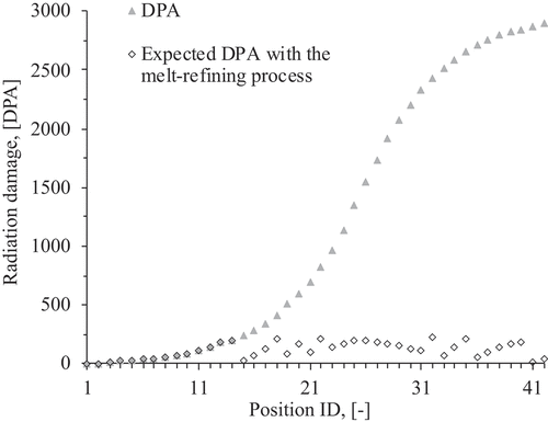
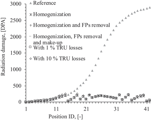
As mentioned in Sec. II, the melt-refining process is applied to recycle the metallic fuel elements and to maintain the cladding material integrity up to the previously demonstrated radiation damage constraint of a 200 DPA cladding level. In this study, 100 DPA corresponds to a fast neutron fluence of 2.2 × 10²³ n/cm2 as calibrated in the previous study.Citation8,Citation23,Citation24,Citation25 The results of the reference core calculations show that the fuel cladding would reach nearly 2900 DPA of radiation damage at the end of equilibrium cycle (EOEC), i.e., at the final burnup step in the equilibrium cycle. In this procedure, the equilibrium condition is determined based on the convergence of the keff, neutron flux distribution, power density distribution, and nuclide number density values of some isotopes such as 239Pu, 241Pu, 235U, and 238U. This high-radiation damage to the cladding is due to the long FCL and long resident time of fuel in the core during operation.
The radiation damage to the cladding in the Reference core and the expected values by the melt-refining process are shown in . It can be seen that with an FCL of 1125 days, the maximum radiation damage to the cladding in some fuel assemblies is much higher than the constraint value. Once the melt-refining process is applied at the EOEC for some proper fuel assemblies, the peak radiation damage to the cladding is conservatively expected to reduce the approximated constraint value of 200 DPA. It is found that the fuel assemblies that should undergo the melt-refining process are those with IDs of 14, 18, 20, 22, 23, 24, 25, 26, 27, 28, 29, 30, 32, 35, and 40. Most of these 15 fuel assemblies that need to be reprocessed are located near the core center. This is because this core region, which is a high-neutron-flux region that is a high-neutron-flux region and a high-neutron-importance region based on the one-group perturbation theory, is located at the core center in the equilibrium cycle.Citation7,Citation8
Fig. 4. The maximum radiation damage to the Reference core and its expected DPA value with the melt-refining process. In this rotational fuel-shuffling scheme, a fresh fuel assembly is loaded at position 1. The fuel assembly is moved inward after the first 25 fuel-shuffling steps (from positions 1 to 25) and then moved outward and discharged after 17 fuel-shuffling steps at position 42.
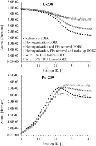
The calculations for the cores undergoing melt refining begin with the fuel compositions at the equilibrium state of the Reference core. The minimum values of keff over the cycle in the equilibrium state of the cores are compared in . The core of the “With 10% TRU losses” is subcritical because of the high percentage of actinides not recovered during the melt-refining process. All of the other cores achieve criticality at the equilibrium state. In comparison with that of the Reference core, the keff values of the cores increase during the course of the equilibrium cycles. A larger excess reactivity is obtained for the core for which the fuel losses are compensated during the melt-refining process. This high excess reactivity is caused by the addition of natural uranium (mostly 238U) to compensate for the fuel losses during the melt-refining process, which results in the generation of more fissile material (239Pu) in the cores, as shown in and . The cores with higher levels of unrecovered actinides during the melt-refining process require larger amounts of compensating natural uranium and have less fissile material content (239Pu) at both the beginning of equilibrium cycle (BOEC) and EOEC, i.e., at the first and final burnup steps in the equilibrium cycle, as shown in and .
Fig. 5. Changes in keff values of the cores in the equilibrium cycle.
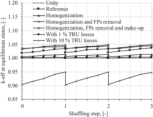
Fig. 6. Axial-averaged nuclide number densities of 238U and 239Pu at the BOEC in the cores at the equilibrium cycle. In this rotational fuel-shuffling scheme, a fresh fuel assembly is loaded at position 1. The fuel assembly is moved inward after the first 25 fuel-shuffling steps (from positions 1 to 25) and then moved outward and discharged after 17 fuel-shuffling steps at position 42.
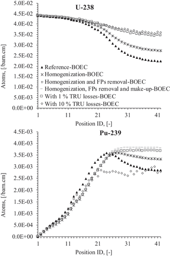
Fig. 7. Axial-averaged nuclide number densities of 238U and 239Pu at the EOEC in the cores at the equilibrium cycle. In this rotational fuel-shuffling scheme, a fresh fuel assembly is loaded at position 42. The fuel assembly is moved inward after the first 25 fuel-shuffling steps (from positions 1 to 25) and then moved outward and discharged after 17 fuel-shuffling steps at position 42.
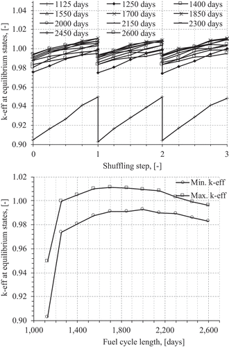
To investigate whether or not the core of the “With 10% TRU Losses” can be critical, the FCL, i.e., the shuffling interval time, is adjusted in the range of 1125 to 2600 days. The changes in keff values at the equilibrium state are shown in . It is found that these cores can reach an equilibrium state but remain not critical throughout the equilibrium cycle. This suggests that the core design should be modified and/or that the fuel losses unrecovered during the melt-refining process need to be reduced.
Fig. 8. Changes in keff values with different FCLs of the core with 10% TRU losses at the equilibrium cycle.
The high-neutron-flux and high-power-density region is retained at the core center region, as shown in and . The power distributions peak at the core center and gradually decrease in the radial direction, as presented in and . The cores that undergo the melt-refining process have slightly lower maximum neutron flux and slightly lower power density because of the effects of both fuel homogenization and removal of FPs. It is clear that the neutron fluxes and the power density distributions are essentially constant shaped from BOEC to EOEC during the equilibrium cycle. This would be a potentially easy and effective way to control the coolant flow rate of each fuel assembly. Because of the gradient of the radial power distribution as shown in , and , the B&B reactor would adopt the orifice concept. In the orifice concept, the coolant flow rate of each fuel assembly will be adjusted by a coolant inlet orifice according to the assembly power as a function of the assembly location. In order to reduce the high change in the flow rate in the core, flow zoning devices, such as in research by Prakash et al. in 2011 (CitationRef. 26), would be applied to the current core design.
Fig. 9. The maximum neutron flux distributions in the cores at the equilibrium cycle.
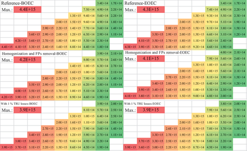
Fig. 10. Axial average power density distributions in the cores at the equilibrium cycle.
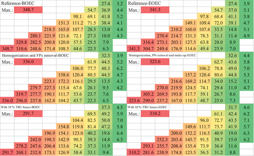
Fig. 11. The maximum neutron fluxes and average power density distributions at the BOEC in the cores at the equilibrium cycle.
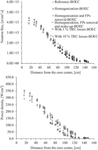
Fig. 12. The maximum neutron fluxes and average power density distributions at the EOEC in the cores at the equilibrium cycle.

As described in Sec. II, once cladding reaches the radiation damage limit, fuel reconditioning has been performed. As a consequence, the radiation damage to the cladding is reduced as shown in . The analysis results reveal that the maximal cladding radiation damage in the critical cores is reduced from 2900 DPA in the Reference core to about 226 DPA in the melt-refining core. This maximum DPA value is slightly higher than the radiation damage constraint of 200 DPA but is still acceptable.
Fig. 13. Maximum radiation damage to the cladding at the EOEC in the cores at the equilibrium cycle. In this rotational fuel-shuffling scheme, a fresh fuel assembly is loaded at position 1. The fuel assembly is moved inward after the first 25 fuel-shuffling steps (from positions 1 to 25) and then moved outward and discharged after 17 fuel-shuffling steps at position 42.
summarizes the analysis results of the cores. The results show that the coolant inlet/outlet temperature, the maximum coolant velocity, the maximum cladding and fuel temperatures, and the maximum core coolant pressure drop are all lower than the design constraint values. This preliminary analysis indicates the feasibility of establishing the B&B mode of operation with rotational fuel shuffling in the S-PRISM core and of applying the melt-refining process. Compensating for fuel loss and FP removal in the melt-refined process results in more uranium loading per cycle and therefore in reduced burnup relative to scenarios that do not compensate for fuel constituent losses in the melt refining.
TABLE II Summary of Analysis Results of the Cores in the Equilibrium Cycle*
IV. CONCLUSIONS
This study investigates the effects of the melt-refining process on the performance of sodium-cooled B&B reactors, called RFBB-MS reactors, with a rotational fuel-shuffling scheme that addresses fuel cladding integrity due to radiation displacement damage and maintains fuel element integrity under a high-burnup condition. The design is based on a commercial-scale fast burner reactor (the S-PRISM reactor). Five scenarios of a core undergoing the melt-refining process are investigated and compared to a core without the melt-refining process: Scenario I, “Homogenization,” is without the removal of FPs during the melt-refining process; Scenario II, “Homogenization and FP Removal,” includes the removal of FPs to a fraction similar to that in the melt-refining process developed in the EBR-II project; Scenario III, “Homogenization, FP Removal, and Make-Up,” is similar to Scenario II but makes up for fuel losses with natural uranium; Scenario IV, “With 1% TRU Losses,” is similar to Scenario III but is evaluated with 1% of actinides not recovered; and Scenario V, “With 10% TRU Losses,” is similar to Scenario III but with 10% of actinides not recovered. It is found that it is neutronically and thermal hydraulically feasible to establish a B&B mode with the rotational fuel-shuffling scheme by reconditioning the fuel whenever its cladding reaches the proven 200 DPA radiation damage limit. In Scenario V, the core is subcritical due to the high percentage of actinides not recovered during the melt-refining process. In all of the other scenarios, the cores are critical. Scenario IV shows some excess reactivity, so the reactor can be critical even if the losses are between 1% and 10%. The numerical analyses also show that the cores in scenarios that include making up fuel losses during the melt-refining process have lower burnup than the other cores due to a larger amount of natural uranium fed each cycle accounting for FP and actinide losses during the melt-refining process. Other characteristics, such as power density distributions, neutron flux profiles, and fertile and fissile nuclide density distributions, are all stable during operation. The analysis results show that a sodium-cooled metal fuel RFBB would be feasible because its melt-refining process limits the DPA of fuel cladding to only slightly higher than 200 DPA. In this study, to simplify the core design and obtain upper-bound estimates, there are no reactivity control assemblies in the core. In future work, further analyses will simulate and investigate a practical reactor design with this concept such as design of the reactivity control systems and the initial core configuration, which are also needed. Analyses of reactivity feedback of the coolant temperature reactivity coefficient, coolant voiding reactivity, fuel temperature reactivity coefficient, and power coefficient are also going to be carried out.
Disclosure Statement
No potential conflict of interest was reported by the author(s).
Additional information
Funding
References
- “ Maximum Fuel Utilization in Fast Reactors Without Chemical Reprocessing,” NEUP Project No. 09-769, University of California, Berkeley/U.S. Department of Energy, Nuclear Energy University Program (2012); https://neup.inl.gov/SiteAssets/Final%20%20Reports/FY%202009/NEUP_Project_No_09-769_Final_Report.pdf ( current as of Dec. 7, 2020).
- S. M. FEINBERG, “Discussion Comment,” Rec. of Proc. Session B-10, ICPUAE, No. 2, Vol. 9, p. 447, United Nations, Geneva, Switzerland (1958).
- “ Advanced Burner Reactor with Breed-and-Burn Thorium Blankets for Improved Economics and Resource Utilization,” Project No. 12-3486, University of California, Berkeley/U.S. Department of Energy, Nuclear Energy University Program; https://neup.inl.gov/SiteAssets/Final%20%20Reports/FY%202012/12-3486%20NEUP%20Final%20Report.pdf#search=Project%20No%2E%2012%2D3486 ( current as of Dec. 7, 2020).
- H. SEKIMOTO and K. RYU, “A New Reactor Burnup Concept CANDLE,” Proc. Physor 2000, Pittsburgh, Pennsylvania, 2000, American Nuclear Society (2000).
- J. GILLELAND et al., “Novel Reactor Designs to Burn Non-Fissile Fuel,” Proc. 2008 Int. Congress Advances in Nuclear Power Plants (ICAPP 2008), Anaheim, California, 2008, American Nuclear Society (2008).
- T. OBARA, K. KUWAGAKI, and J. NISHIYAMA, “Feasibility of Burning Wave Fast Reactor Concept with Rotational Fuel Shuffling,” Proc. Int. Conf. Fast Reactors and Related Fuel Cycles: Next Generation Nuclear Systems for Sustainable Development (FR17), Yekaterinburg, Russian Federation, June 26–29, 2017, IAEA-CN245-051, International Atomic Energy Agency (2017).
- K. KUWAGAKI, J. NISHIYAMA, and T. OBARA, “Concept of Stationary Wave Reactor with Rotational Fuel Shuffling,” Nucl. Sci. Eng., 191, 178 (2018); https://doi.org/10.1080/00295639.2018.1463744.
- V. K. HOANG et al., “Feasibility of Sodium-Cooled Breed-and-Burn Reactor with Rotational Fuel Shuffling,” Nucl. Sci. Eng., 196, 1, 109 (2022); https://doi.org/10.1080/00295639.2021.1951063.
- A. E. DUBBERLEY et al., “SuperPRISM Oxide and Metal Fuel Core Designs,” Proc. ICONE 8, Baltimore, Maryland, April 2–6, 2000.
- R. D. LEGGETT and L. C. WALTERS, “Status of LMR Fuel Development in the United States of America,” J. Nucl. Mater., 204, 23 (1993); https://doi.org/10.1016/0022-3115(93)90195-5.
- C. E. STEVENSON, The EBR-II Fuel Cycle Story, American Nuclear Society, La Grange Park, Illinois (1987).
- J. C. HESSON, M. J. FELDMAN, and L. BURRIS, “Description and Proposed Operation of the Fuel Cycle Facility for the Second Experimental Breeder Reactor (EBR-II),” ANL-6605, Argonne National Laboratory (1963).
- E. GREENSPAN and F. HEIDET, “Energy Sustainability and Economic Stability with Breed and Burn Reactors,” Prog. Nucl. Energy, 53, 794 (2011); https://doi.org/10.1016/j.pnucene.2011.05.002.
- C. D. SANZO, E. GREENSPAN, and J. L. VUJIC, “Maximum Burnup of Breed and Burn Reactors with Limited Separation Processes,” Trans. Am. Nucl. Soc., 111, 1278 (2014).
- T. K. KIM et al., “Core Design Studies for a 1000 MWth Advanced Burner Reactor,” Ann. Nucl. Energy, 36, 3, 331 (2009); https://doi.org/10.1016/j.anucene.2008.12.021.
- E. A. HOFFMAN, W. S. YANG, and R. N. HILL, “Preliminary Core Design Studies for the Advanced Burner Reactor over a Wide Range of Conversion Ratios,” ANL-AFCI-177, Argonne National Laboratory, Nuclear Engineering Division (Sep. 29, 2008).
- S. QVIST and E. GREENSPAN, “Design Space Analysis for Breed-and-Burn Reactor Cores,” Nucl. Sci. Eng., 182, 197 (2016); https://doi.org/10.13182/NSE14-135.
- A. E. DUBBERLEY, “S-PRISM High Burnup Metal-Fuel Core Design,” Proc. ICAPP ’03, Cordoba, Spain, May 4–7, 2003.
- J. C. HESSON, M. J. FELDMAN, and L. BURRIS, “Description and Proposed Operation of the Fuel Cycle Facility for the Second Experimental Breeder Reactor (EBR-II),” ANL-6605, p. 193, Argonne National Laboratory (Apr. 1963).
- J. LEPPÄNEN, “Serpent—A Continuous-Energy Monte Carlo Reactor Physics Burnup Calculation Code,” VTT Technical Research Centre of Finland (2015).
- M. B. CHADWICK et al., “ENDF/B-VII.0: Next Generation Evaluated Nuclear Data Library for Nuclear Science and Technology,” Nucl. Data Sheets, 107, 12, 2931 (2006); https://doi.org/10.1016/j.nds.2006.11.001.
- COMSOL 5.4a, Multiphysics Modeling, Finite Element Analysis, and Engineering Simulation Software website; https://www.comsol.com (current as of Apr. 5, 2020).
- V. K. HOANG, J. NISHIYAMA, and T. OBARA, “Design Concepts of Small CANDLE Reactor with Melt-Refining Process,” Prog. Nucl. Energy, 108, 233 (2018); https://doi.org/10.1016/j.pnucene.2018.05.019.
- V. K. HOANG, J. NISHIYAMA, and T. OBARA, “Effects of Compensating for Fuel Losses During the Melt-Refining Process for a Small CANDLE Reactor,” Ann. Nucl. Energy, 135, 106969 (2020); https://doi.org/10.1016/j.anucene.2019.106969.
- J. A. KARIM, J. NISHIYAMA, and T. OBARA, “Application of Melt and Refining Procedures in the CANDLE Reactor Concept,” Ann. Nucl. Energy, 90, 275 (2016); https://doi.org/10.1016/j.anucene.2015.12.001.
- V. PRAKASH et al., “Experimental Qualification of Subassembly Design for Prototype Fast Breeder Reactor,” Nucl. Eng. Des., 241, 8, 3325 (2011); https://doi.org/10.1016/j.nucengdes.2011.04.040.