Abstract
A subset of pressurized water reactor (PWR) studies from Exercise II-2 of the Uncertainty Analysis in Modeling for Light Water Reactors (UAM-LWR) benchmark study has been performed to quantify the importance of both nuclear data uncertainties and manufacturing uncertainties in an assembly depletion calculation and a mini-core rod movement transient. The depletion study of the 15 × 15 PWR assembly using the SAMPLER and TRITON modules of the SCALE code system revealed a maximum uncertainty in keff of 0.49% for fresh fuel, decreasing to 0.38% at the midpoint of the fuel cycle and rising back to 0.48% at the end of the fuel cycle. Uncertainties and correlations of various homogenized cross sections and other group constant data, such as keff, have been determined, and the effect of randomly applied manufacturing uncertainties was found to be largely negligible relative to nuclear data uncertainties for bulk lattice parameters. However, for local parameters, such as the pin power factors, assembly discontinuity factors, and diffusion coefficients, the effects from manufacturing uncertainties were appreciable and sometimes dominant.
Nuclear data uncertainties were found to be the dominant contributors to uncertainty in the isotopic composition of the overall assembly, with the exception of very early in the fuel cycle, where manufacturing uncertainties such as perturbations to the fuel density and pin radius made nonnegligible contributions to total uncertainty. The contribution of manufacturing uncertainties to isotopic uncertainties was nonnegligible at a pin-by-pin level, but still smaller than the contributions from nuclear data uncertainty. Studies of the PWR mini-core rod movement transient using homogenized data from the SCALE models in the PARCS diffusion code showed little difference between the tested modeling approaches and demonstrated that nuclear data uncertainties dominated the manufacturing uncertainties in the global figures of merit considered, such as the equilibrium core boron concentration, the maximum core power factor, and the maximum reactivity insertion. For local effects, such as maximum pin power during the transient, the randomly applied manufacturing uncertainties were dominant. It was found in general that for global system properties, nuclear data uncertainties made significantly larger contributions to total uncertainty, whereas for local parameters the impact of manufacturing uncertainties was at least nonnegligible, and for some parameters, dominant.
I. INTRODUCTION
The safety analysis and licensing process for nuclear power plants relies heavily on the use of simulation software to predict a plant’s response during both normal operation and under accident conditions. Of utmost importance in this analysis are not only the values for key figures of merit predicted by the simulation, such as peak pin powers or ramp rates, but also the degree of confidence with which each figure of merit can be predicted. Operational limits for various reactor parameters are determined using a combination of the predicted values and their margins of uncertainty to ensure safety limits are observed during any predicted accident within the design basis.
Due to limitations in computing power, early safety analyses used conservative assumptions to account for the uncertainty in modeling, code inputs, and operational plant states. While these conservative approaches allowed operators to define their safe operating envelope, past studies have demonstrated that conservative approaches can lead to simulations that deviate from actual plant behavior.Citation1 Recent approaches have taken advantage of significant improvements in computing power to perform detailed propagation of uncertainties through multistep Monte Carlo methods to generate more accurate predictions of the operating margins.Citation2
In recognition of the international interest in quantifying these uncertainties, the Organisation for Economic Cooperation and Development’s Nuclear Energy Agency established a benchmark study on Uncertainty Analysis in Modeling for Light Water Reactors (UAM-LWR). The benchmark established a series of exercises split into three phrases to improve the quantification of uncertainties in the simulation of light water reactors (LWRs). The phases defined by the benchmark areCitation3
Phase I (Neutronics):
Exercise I-1 (Cell Physics): focused on the derivation of the multigroup microscopic cross-section libraries and their uncertainties
Exercise I-2 (Lattice Physics): focused on the derivation of the few-group macroscopic cross-section libraries and their uncertainties
Exercise I-3 (Core Physics): focused on the core steady-state standalone neutronics calculations and their uncertainties
Phase II (Core)
Exercise II-1 (Fuel Physics): fuel thermal properties relevant to steady-state and transient performance
Exercise II-2 (Time Dependent Neutronics): neutron kinetics and fuel depletion standalone performance
Exercise II-3 (Bundle Thermal Hydraulics): thermal-hydraulic fuel bundle performance
Phase III (System)
Exercise III-1 (Core Multi-Physics): coupled neutronics/thermal-hydraulic core performance
Exercise III-2 (System Thermal Hydraulics): thermal-hydraulic system performance
Exercise III-3 (Coupled Core-System): coupled neutronics/thermal-hydraulic performance
Exercise III-4: Comparison of best estimate plus uncertainty versus conservative calculations.
In this work, a subset of the studies defined in Exercise II-2 have been performed. Specifically, case II-2a studying the propagation of uncertainties in a typical depletion calculation for a pressurized water reactor (PWR) fuel assembly and case II-2b, a neutronics study of the propagation of uncertainty in a rod movement transient simulation for a PWR mini core.Citation4 Both exercises present a unique opportunity to elucidate the uncertainties in key reactor physics phenomena.
This paper includes a summary of the description of each exercise performed, results obtained for the fuel assembly depletion case demonstrating the evolution of uncertainties throughout the expected life of the fuel, results of the uncertainty propagation on the mini-core rod movement transient, and some concluding remarks on this work and steps for future work.
II. MODEL DESCRIPTION
The UAM-LWR benchmark study has led to the development of numerous tools for the study of uncertainties in reactor physics. Among these tools is the SAMPLER super sequence of the SCALE code package, which is used in this work. SAMPLER controls the repeated execution of a SCALE sequence, in this case TRITON (CitationRef. 5). Within each sequence, perturbations can be applied to the nuclear data used in the calculation as well as the other input data provided by the user (such as the geometry of the assembly). Each execution of the TRITON code yields an output corresponding to the specific set of perturbations applied by SAMPLER. The major inputs requested by SAMPLER are the perturbed nuclear data sets included with SCALE that were based on the nuclear date covariance uncertainty matrices. The SCALE code package includes 1000 precalculated perturbed nuclear data libraries, allowing for a total of 1001 (the reference nuclear data plus each perturbed nuclear data set) simulations to be performed for a given model.
The SAMPLER/TRITON code sequence is sufficient on its own for the PWR fuel assembly depletion study. However, to complete the PWR mini-core transient study a core-level diffusion solver was required. In this work, PARCS (CitationRef. 6), a three-dimensional multigroup neutron diffusion solver released by the U.S. Nuclear Regulatory Commission was used. The output of each TRITON execution was converted to PARCS input data (in the form of PMAXS files) using the GenPMAXS tool.Citation7 For each TRITON execution, the mini-core transient was simulated once. All perturbations were applied via the PMAXS homogenized cross-section data files (i.e., the PARCS input file was not altered between trials).
II.A. Exercise II-2a Description
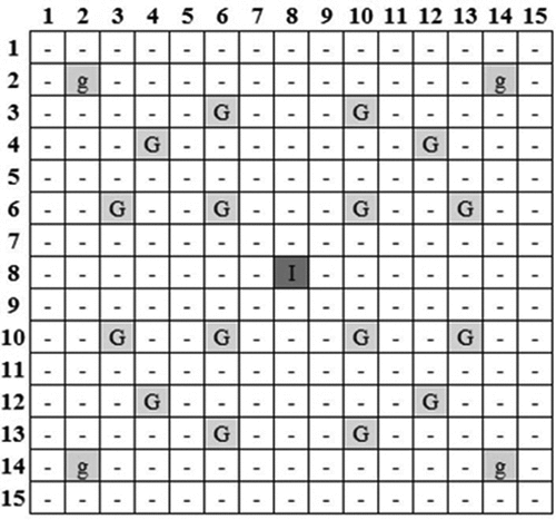
Exercise II-2a models the typical depletion calculation of a PWR fuel assembly using a TMI-1 15 × 15 pin assembly as the test case. The fuel assembly, as defined by the benchmark specifications,Citation2,Citation4 is shown in . The enrichment of the fuel pins is 4.12% 235U. The gadolinium poison pins (Gd) have the same enrichment as the fuel pins, but contain 2% Gd by weight. The depletion calculation is performed at nominal hot full-power (HFP) conditions, defined in , to a final burnup of 60 megawatt days per kilogram of uranium (MWd/kg).
TABLE I HFP Conditions for the TMI-1 Fuel Assembly Depletion Calculation*
Fig. 1. The 15 × 15 TMI-1 fuel assembly modeled in this work. Cells containing g represent fuel pins with poison, cells containing G are guide tubes, and the cell containing I is the instrumentation tube. All other cells are standard fuel pins.Citation4
In addition to propagating nuclear data uncertainties in the depletion calculation, a subset of manufacturing uncertainties defined in the UAM-LWR benchmark were considered (see ). The distribution of all manufacturing uncertainties was assumed to be normal.Citation4
TABLE II Manufacturing Uncertainties Considered in the TMI-1 Fuel Assembly Depletion Study
The TMI-1 fuel assembly was modeled in TRITON using the NEWT transport solver. The 15 × 15 assembly had a square pitch of 21.81 cm and was modeled with a 60 × 60 global mesh grid. Sensitivity analyses were performed on the mesh, and the grid size used provided sufficiently accurate results while still being computationally efficient. In this model, a single fuel material was used to track the composition of all fuel pins in the assembly simultaneously. Similarly, a single fuel-poison material was used to track the composition of all four poison pins. Additional work was performed to consider the impact of using pin-specific compositions, and the results are discussed in subsequent sections.
The PWR lattice considered in the benchmark study contained 225 pins (204 of which were fuel pins and an additional four which were fuel pins containing burnable poison). To accurately quantify the impact of manufacturing uncertainties on the lattice level calculation results, it was necessary to apply manufacturing uncertainties on a pin-by-pin basis. This approach is only possible if the pins are modeled within SCALE as separate entities, each requiring its own self-shielding and depletion calculations. To reduce the computational costs associated with this approach, a quarter-assembly model was considered with reflective boundary conditions on all sides. The quarter assembly was modeled using a 30 × 30 global grid, and mesh sensitivity studies demonstrated that the reduction in grid did not contribute significantly to the uncertainty calculations. The model had 49 complete pins and 15 partial pins modeled. Of these, 58 were regular fuel pins (including 14 of the partial pins), one was a fuel pin containing burnable poison, and the remaining pins were either guide tubes or the instrumentation tube. Manufacturing uncertainties were only applied to the fuel and fuel-burnable poison pins.
The assembly depletion studies were done with the full set of nuclear data perturbations available in SCALE (all 1000 perturbations for the cross sections, fission product yields, and radioactive decay constants) for both the full-assembly (with pin-averaged depletion) and the quarter-assembly model (with pin-specific depletion and self-shielding). The full-assembly model was simulated with the nuclear data uncertainties only since computational limits prevented the application of pin-by-pin depletion and manufacturing perturbations (i.e., only a single material was used to model the composition of the fuel pins, and thus depletion was tracked for the aggregate of the pins, rather than on a pin-by-pin basis). The quarter-assembly model was tested using both the nuclear data uncertainties alone and the combined nuclear data and manufacturing uncertainties. Additionally, the effect of using separate fuel materials for each pin (i.e., each pin was modeled with an individual, unique fuel material, which was depleted independent of the other fuel pins) was considered. The four key test cases are outlined . The approximate computational cost of each study is also shown. The depletion calculations were performed on a Dell XPS desktop PC with a 10 core 3.3-GHz Intel Xeon W-2155 CPU and 251 Gb of usable DDR4 RAM. Comparison tests were performed to confirm the equivalency of the different models.
TABLE III Description of Cases of Interest Studied for the TMI Assembly Depletion Case
II.B. Exercise II-2b Description
Exercise II-2b describes a kinetics-specific transient within a mini PWR core. The mini core contained nine fuel assemblies (identical to the assembly modeled in Exercise II-2a) surrounded by reflector assemblies. All nine fuel assemblies were assumed to be fresh fuel. The layout of the PWR mini core is shown in . The center fuel assembly contained a control rod cluster of length 3657.6 mm (the same as the active height of the core). Reflectors at the top and bottom of core with heights of 21.84 cm were modeled. The mini-core transient was simulated using homogenized data from the FA-SP-ND model, the QA-IP-ND model, and the QA-IP-ALL model. Though the same models were used, separate simulations were required to prepare the homogenized data as Exercise II-2a was performed with HFP conditions and Exercise II-2b was performed with hot zero-power (HZP) conditions, as defined in . The initial power of the PWR mini core was defined in the benchmark as 0.1409 MW(thermal).
TABLE IV HZP Conditions for the PWR Mini-Core Rod Movement Transient Study*
Fig. 2. The layout of the mini PWR core considered for the kinetics-only rod movement transient. The unrodded and rodded assemblies are denoted by U and R, respectively.Citation4

The transient studied in this case considered the movement of the central control assembly. The control rod, which extends the entire length of the active core, was fully inserted at t = 0. The rod was withdrawn at constant velocity over a period of 10 s by 438.912 mm, or 12% of the rod’s full length. The control rod was then fully reinserted at a constant velocity over a period of 20 s. An additional 20 s was simulated after the rod was fully reinserted.
The PWR mini core was modeled in PARCS using two and four calculation nodes per assembly (including reflector assemblies) in the x- and y-directions. It was found that transient pin power factors could not be calculated with more than two calculation nodes per assembly in the x- and y-directions, and thus the transient simulations were performed with both nodalizations to ensure the selected nodalization was sufficient. The z (axial) direction was modeled with 24 calculation nodes in the active height of the core, with an additional node for the top and bottom reflectors. Differences between the 2 × 2 calculation mesh per node and the 4 × 4 calculation mesh per node were found to be small.
III. ASSEMBLY DEPLETION STUDY RESULTS
Depletion studies were performed using each of the PWR assembly models from fresh conditions to the specified benchmark final burnup. These studies were performed using identical cycle data for each case. The following sections discuss key outputs of the lattice-level depletion calculations and how they were impacted by nuclear data perturbations, and in the case of the quarter-assembly model, manufacturing uncertainties.
III.A. keff
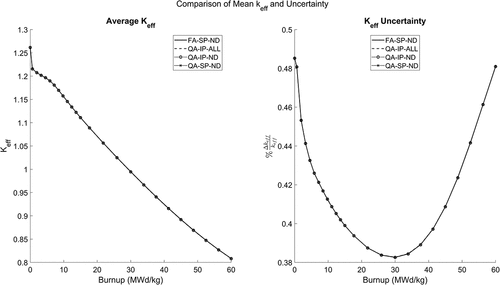
The average assembly neutron multiplication factor and its uncertainty are shown to agree closely across the sampled cases in . The similarity of the keff uncertainty curve for the quarter-assembly case with manufacturing uncertainties to the other cases implies the tested manufacturing uncertainties had little impact on the output uncertainty of keff. The relative uncertainty in keff was found to be about 0.49% for fresh fuel in all cases, decreasing to around 0.38% at the middle of the fuel’s irradiation, before increasing to around 0.48% at the highest observed burnup. The behavior of the uncertainty in keff with burnup was found to be similar to studies of other LWR assemblies, which provided context for possible drivers of this behaviorCitation8 (specifically, in CitationRef. 8). The observed means and standard deviations were found to agree to within approximately 0.1% across all cases.
Tests for normality were performed using the Anderson-Darling test. The null hypothesis of normality was not rejected at the 5% significance level for the keff distributions of the beginning of cycle (BOC) and end of cycle (EOC) fuel and at most calculation points during the fuel cycle. However, it was observed that for burnups between 13.7 and 30 MWd/kg (a total of six calculation steps), the null hypothesis was rejected at the 5% significance level in the nuclear data only cases. Similarly, for the quarter-assembly case with nuclear data and manufacturing uncertainties, the null hypothesis was rejected for burnups between 12.39 and 30 MWd/kg (this represented only one additional calculation step where the null hypothesis was rejected relative to the other cases). This indicates that as the uncertainty transitions toward the minimum, there is some deviation from normality in the output uncertainty distributions.
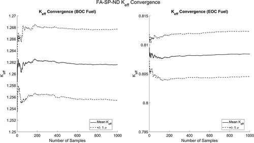
To ensure a sufficient number of samples were used, the convergence of the average keff value and its uncertainty was checked at BOC and EOC for the full-assembly case with nuclear data uncertainties and the quarter-assembly case, which included manufacturing uncertainties. The convergence of keff and its uncertainty for the full-assembly model is shown in . In all cases, it was found the absolute standard deviation of keff was lower for EOC fuel. Additionally, the mean keff value was found to vary less as a function of the number of samples for the EOC fuel than for the BOC fuel. In all four convergence tests, the results appear to be well converged after approximately 600 samples.
III.B. Homogenized Cross Sections
Homogenized cross sections are a critical output of lattice calculations as they are typically used as input for core behavior modeling in a diffusion code. The output uncertainties of these homogenized cross sections are thus essentially input uncertainties to the next stage of the reactor modeling process.
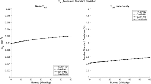
The mean of the fast absorption cross section and its uncertainty are shown in . Differences of up to 0.02% were observed between the mean values obtained using the full-assembly geometry compared to the quarter-assembly model. The application of manufacturing uncertainties was found to slightly increase the uncertainty in ∑A1 compared to nuclear data uncertainties alone, with the maximum relative difference between standard deviations found to be 2.8% between the quarter-assembly cases with and without manufacturing uncertainties (QA-IP-ALL and QA-IP-ND, respectively) at the second calculation step. The application of manufacturing uncertainties was also found to cause the ∑A1 distributions to reject normality at some calculation steps. For the case including manufacturing uncertainties, normality of the ∑A1 distribution was rejected at the 5% significance level at the calculation step corresponding to a burnup of 0.65 MWd/kg and for burnups at or above 37.6 MWd/kg (seven calculation steps).
Fig. 5. Mean and standard deviation in the fast group absorption homogenized cross section throughout fuel life.
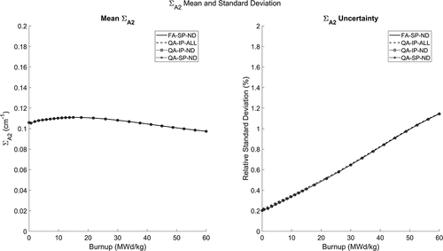
The thermal absorption cross section ∑A2 mean and uncertainty are shown in . The maximum variation in the mean between cases was 0.13% and occurred at 45 MWd/kg. The maximum relative difference in the standard deviations between cases was found to be about 9.0% and occurred at the first calculation step between the quarter-assembly case with manufacturing uncertainties (QA-IP-ALL) and the quarter-assembly case with a single fuel material (QA-SP-ND). It was found that the null hypothesis of normality was rejected at the 5% significance level for the first calculation step in the nuclear data cases. The null hypothesis was not rejected at any subsequent calculation steps, nor was it rejected for the first calculation step in the manufacturing uncertainty case.
Fig. 6. Mean and standard deviation in thermal group absorption homogenized cross section throughout the fuel life.
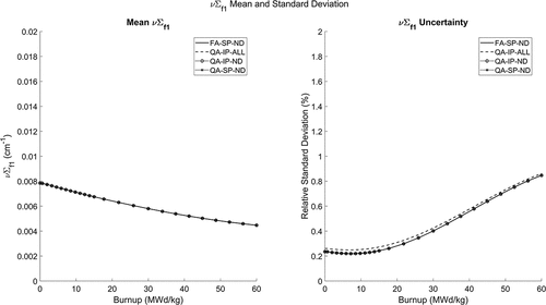
The average ν∑f1 cross sections are shown in and were found to agree closely across all cases (within 0.1%). The inclusion of manufacturing uncertainties was found to slightly increase the uncertainty in ν∑f1 throughout the fuel cycle, with a maximum relative difference of 13.6% observed between the standard deviations of the quarter-assembly cases with and without manufacturing uncertainties (QA-IP-ALL and QA-IP-ND) at approximately 10 MWd/kg, with similar magnitude discrepancies observed between the case with manufacturing uncertainties and the remaining cases. The null hypothesis of normality was not rejected for any calculation step across the four test cases.
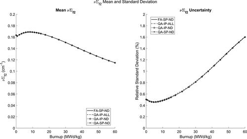
The mean and standard deviation of the thermal fission cross section, multiplied by ν, is shown in . The largest observed difference in the ν∑f2 cross section between cases was 0.21% at 45 MWd/kg. The largest relative difference in standard deviations was 2.66% at 8.48 MWd/kg between the quarter-assembly cases with and without manufacturing uncertainties (QA-IP-ALL and QA-IP-ND). The null hypothesis of normality was not rejected for any calculation step across the four test cases.
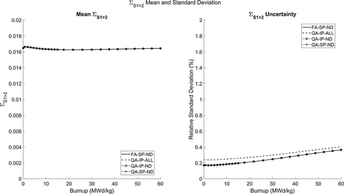
The mean and relative uncertainty in the fast to thermal downscatter cross section is shown in . The mean value agrees closely across all cases at BOC. The presence of manufacturing uncertainties was found to increase the uncertainty in the downscatter cross section, with a maximum relative difference in the standard deviation of about 40.1% observed early in the fuel cycle at around 1.95 MWd/kg. The null hypothesis of normality was rejected at the 5% significance level for burnups between 4.56 and 15 MWd/kg in the quarter-assembly case with the individual pin materials (QA-IP-ND) case and between 5.87 and 15 MWd/kg (one fewer calculation step) for the single material cases (FA-SP-ND and QA-SP-ND). The null hypothesis of normality was not rejected at the 5% significance level for the case including manufacturing uncertainties.
The value and uncertainty of D1 and D2 were not found to vary significantly with burnup. The mean values of D1 were found to agree to within 0.03% throughout the fuel cycle, while the presence of manufacturing uncertainties led to a maximum relative increase in the standard deviation of 32.4% at 7.17 MWd/kg. Normality was rejected at the 5% significance level for burnups between 30 and 60 MWd/kg in the nuclear data cases.
For the thermal diffusion coefficient, the mean values agreed to within 0.03% throughout the fuel cycle, and the incorporation of manufacturing uncertainties led to a maximum relative increase in the standard deviation of 3.65% at 9.78 MWd/kg. The null hypothesis of normality was not rejected at the 5% significance level for D2.
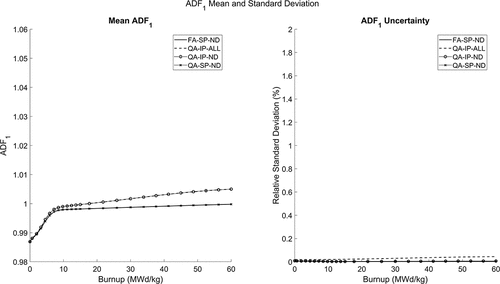
Last, the assembly discontinuity factors (ADFs) are considered in and . The mean value was found to be affected by the pin modeling (single or individual) used. A maximum difference in the ADF1 mean of 0.52% was observed at EOC. Large differences in the uncertainty were noted, primarily due to the inclusion of manufacturing uncertainties. This was expected since the ADFs are a local phenomenon primarily dependent on the adjacent pins. So, while global phenomena (e.g., keff) have the effect of manufacturing uncertainties canceled out by randomly generated perturbations offsetting each other when a large number of perturbations are applied, for local parameters such as ADFs or pin powers, the uncertainty is dependent on the specific properties of the pins in each local region of the assembly, and the number of pins is small so the variations do not completely cancel out. The standard deviation for the case including manufacturing uncertainties (QA-IP-ALL) was up to 13 times larger than the other cases, but it was noted the largest observed relative uncertainty across all cases and burnup steps was 0.05%, suggesting the large variation in standard deviations likely has little practical importance. Normality was not rejected at the 5% significance level for ADF1.
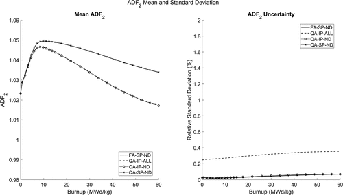
The impact of the pin modeling selections was once again apparent in ADF2. The maximum difference in mean values between the different cases was 1.6% and was observed at EOC. Like ADF1, a large relative difference in standard deviations was observed (up to nearly a factor of 12 difference in absolute standard deviations), but the maximum relative uncertainty in ADF2 was found to be below 0.4%, again suggesting the large relative change in standard deviations has only minor practical effects. The null hypothesis of normality was not rejected for any burnup step across the four cases.
III.B.1. Homogenized Cross-Section Correlations
For each calculation point, Pearson correlation coefficients were calculated for the homogenized data using MATLAB. The correlation coefficients at each burnup step were calculated independently of the correlation coefficients at all other burnup points. The correlation coefficients at select burnup steps are shown for select cases in and . The single pin material cases were found to agree closely, and thus only the full-assembly case is shown. The tracking of individual pin compositions mainly affected the correlations between ADFs and the remaining homogenized data. The BOC correlation coefficients were found to agree well between the nuclear data cases. The inclusion of manufacturing uncertainties significantly impacted the correlation between ADFs in the QA-IP-ALL case. The ADFs in the manufacturing uncertainty case at BOC were strongly negatively correlated, while in the remaining cases they were strongly positively correlated at BOC. The manufacturing uncertainties were found to have the most significant impact on correlations involving ADFs or diffusion coefficients.
Fig. 12. Correlation coefficients for the homogenized properties from the full-assembly case at select burnups.
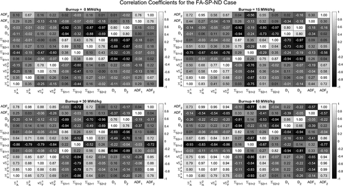
Fig. 13. Correlation coefficients for the homogenized properties from the quarter-assembly case with manufacturing uncertainties at select burnups.
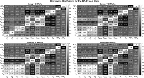
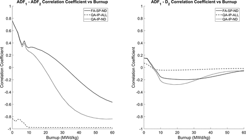
It was found that some correlation coefficients changed with burnup. Changes with burnup were typically observed for pairs of homogenized data that had relatively weak relationships at BOC. The correlations (or anticorrelations) were generally observed to grow stronger as burnup increased, although the rate of change was typically higher in the first half of the fuel cycle. Most correlation coefficients were observed to maintain the same sign throughout the fuel cycle, with the strength of the correlation (or anticorrelation) growing. However, some correlations, for example, the ADF1-∑A2, ADF1-ADF2, and ∑A1-ν∑f1 correlations, were found to change signs over the fuel cycle. The most significant changes were observed in the correlation between ADF1 and ADF2, shown in . Also shown is the ADF1-D2 correlation, which underwent a less significant change with burnup when manufacturing uncertainties were included. The ADF1-ADF2 correlation was found to be affected by both the use of individual pin material tracking and the inclusion of manufacturing uncertainties, but still underwent significant changes throughout the fuel cycle in the full-assembly model with a single pin material.
III.C. Isotope Concentrations
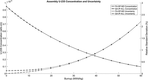
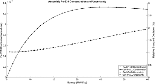
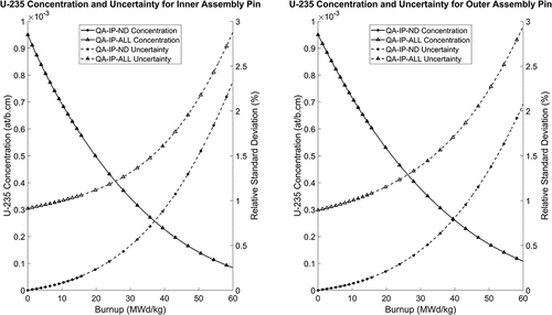
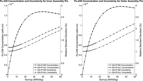
The concentration and uncertainty of isotopes within the fuel were tracked throughout the depletion cycle. For demonstration, the assemblywise concentrations of 235U and 239Pu are shown in and . In general, it was observed that the inclusion of manufacturing uncertainties did not significantly affect the uncertainty of the assembly isotopic compositions (again, the global effect of manufacturing uncertainties was being reduced by individual pin perturbations canceling each other out). However, some effect was observed in the uncertainties of the composition of individual pins, as shown in and . As expected, for isotopes in the specified composition of the fuel (such as 235U and 238U) there is no uncertainty at BOC except in the quarter-assembly case with manufacturing uncertainties. However, the uncertainty of 235U at the assembly level in the case including manufacturing uncertainties was found to converge toward the uncertainty of the remaining cases over the life of the fuel. The uncertainty in 238U in the manufacturing uncertainty case was found to be significantly higher than the remaining cases throughout the fuel cycle, but the overall magnitude of the uncertainty was small (reaching a maximum below 0.13% by EOC), and thus the increased uncertainty due to manufacturing uncertainties likely has few practical impacts. The concentration of 155Gd (from the burnable poison pins) was found to decrease to negligible levels around approximately 10 MWd/kg, with its uncertainty generally increasing with burnup to that point.
III.D. Pin Power Factors
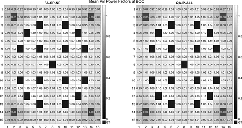
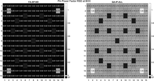
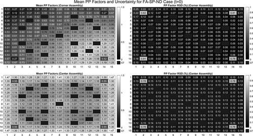
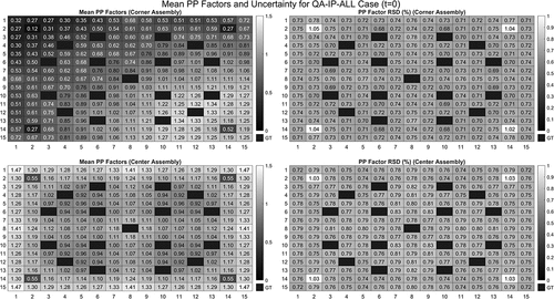
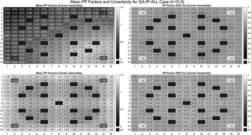
Assembly pin power factors were observed throughout the depletion of the fuel. For ease of comparison, the quarter-assembly model pin powers were reflected to generate 15 × 15 pin power maps, consistent with the full-assembly geometry. Mean pin power factors for select cases at BOC are shown in . No notable variations were observed between the four cases. The relative standard deviation (RSD) of the pin power factors at BOC is shown in . It was found that the introduction of manufacturing uncertainties significantly impacted the uncertainty in the pin power factors, as uncertainties on the order of 0.75% were observed in the fuel pins of the quarter-assembly case with manufacturing uncertainties compared to negligible uncertainty in the remaining cases. Similarly, the introduction of manufacturing uncertainties increased the uncertainty of the pin power factors in the burnable poison pins, rising from around 0.77% to around 1%.
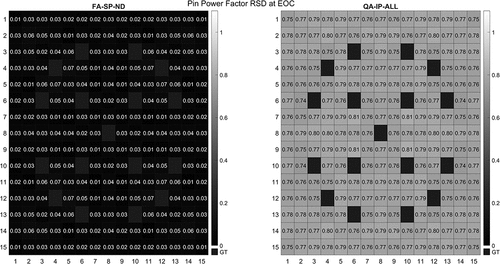
For EOC pin powers, slight differences were observed between the models. Small variations between the case with individual pin materials and a single pin material demonstrated the impact of tracking pin compositions individually rather than as a lumped material, but the impact of manufacturing uncertainties was found to be much more significant than that of individual pin materials. RSDs for the EOC pin power factors are shown in . In all cases, the uncertainty of the pin power factor in the pins containing burnable poison decreased to a level consistent with the fuel pins (as expected, as very little burnable poison remains in the pins).
IV. PWR MINI-CORE TRANSIENT RESULTS
The PWR mini-core transient from Exercise II-2b of the UAM-LWR benchmark study was completed with three sets of homogenized cross-section data corresponding to the full-assembly nuclear data case (FA-SP-ND), the quarter-assembly case with nuclear data uncertainties (QA-IP-ND), and the quarter-assembly case with manufacturing uncertainties (QA-IP-ALL). Note that while the geometry model, pin material modeling, and uncertainties selected were the same, the conditions of Exercise II-2b are at HZP, rather than the HFP conditions used in Exercise II-2a. The reference homogenized cross sections were computed for the unrodded assembly at HZP thermal-hydraulic conditions and a boron level of 900 ppm. Three additional branches were calculated, each with only a single change relative to the reference conditions: a rodded assembly, an assembly with a low boron level (5 ppm), and an assembly with a high boron level (1800 ppm).
The following sections summarize the key results of the mini-core rod movement transient and the effect of the uncertainties studied. It should be noted that while some uncertainty was observed in the kinetic parameters critical to the evolution of the transient (as a result of differences in the nuclear data), a more complete accounting of the kinetic parameter uncertainty, as described in other works,Citation9 was not able to be performed with the available tools, and thus future improvements to the results presented here may be required.Footnotea The results presented in this section were obtained with the 4 × 4 radial nodalization, with the exception of the pin power factors, which were obtained with the 2 × 2 radial nodalization.
IV.A. Initial Core State
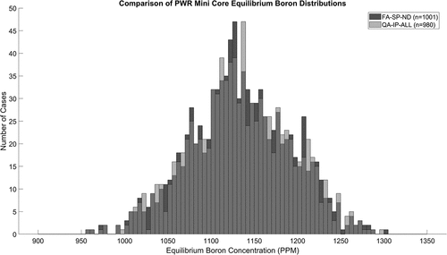
The application of nuclear data and manufacturing uncertainties caused variations in the initial (t = 0) core state. Before the rod withdrawal began, a critical boron search was performed for each trial to ensure each transient started from a critical state. The distribution of critical boron levels for the two test cases is shown in . The application of manufacturing uncertainties was not found to significantly change the observed results. The null hypothesis of normality was not rejected at the 5% significance level for either case. The mean and standard deviations of the equilibrium boron levels are shown in .
TABLE V Equilibrium Boron Levels for Each Case
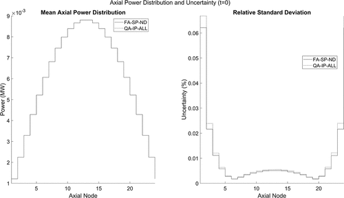
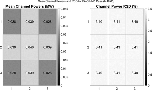
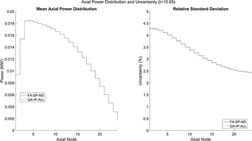
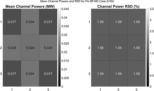
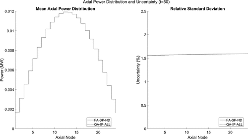
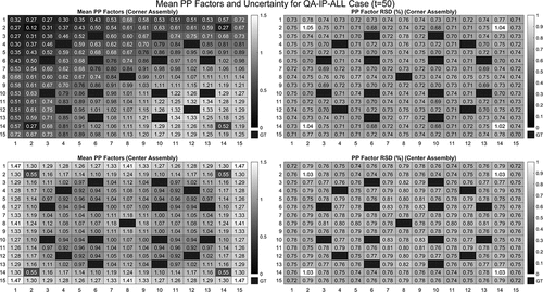
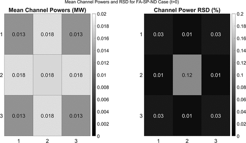
The initial mean radial assembly power distributions and RSDs for the 3 × 3 mini core are shown in for the full-assembly case. Differences between the nuclear data and manufacturing uncertainty cases were negligible. The initial axial power distribution and its uncertainty are shown for both cases in . Pin power factors and uncertainties for the corner and center assemblies are shown in and . The introduction of manufacturing uncertainties was not found to significantly affect the initial power distributions or uncertainties for the PWR mini core, but the increase in pin power uncertainties was found to be nonnegligible.
Fig. 23. Initial mean channel powers and RSDs for the PWR mini core modeled with homogenized data from the full-assembly model.
IV.B. Transient Evolution
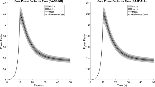
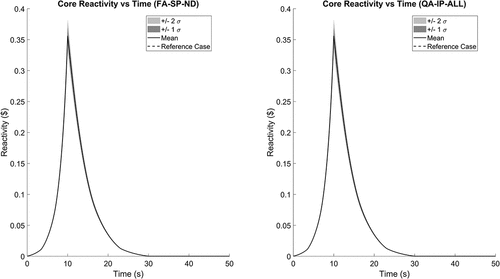
The PWR mini-core transient experienced an initial increase in reactivity as the center assembly control rod was withdrawn over the first 10 s, followed by a decrease in reactivity back to criticality as the control rod was reinserted over a period of 20 s. An additional 20 s were simulated following the complete reinsertion of the rod. The transient was simulated using time steps of 0.05 s. No thermal-hydraulic modeling was performed. The peak core power was observed at either 10.6 or 10.65 s for all samples across both models, with the majority of peak powers occurring at 10.65 s.
For the full-assembly case, a total of 893 of the 1001 samples reached the peak core power at 10.65 s. For the quarter-assembly case with manufacturing uncertainties, a total of 876 out of 980 samples reached the peak core power at 10.65 s. Testing of the mini-core transient with homogenized data from the quarter-assembly case with nuclear data only found 895 out of 1001 samples reached the peak core power at 10.65 s. The similarities between cases with and without manufacturing uncertainties was reasonable based on other works, which identified D1 and ∑A1 as the most significant contributors to the variance in results for similar transients.Citation10,Citation11 As discussed earlier in this work, the variability in D1 is small in all cases (incorporating manufacturing uncertainties had a minimal impact on the variability of D1) and the uncertainty in ∑A1 for fresh fuel was driven mostly by nuclear data uncertainties, which are the same between cases, rather than manufacturing uncertainties.
The mean and standard deviations of the mini-core power (normalized to the initial power) and reactivity (in dollars) are shown alongside the results for the reference case in and , respectively. The maximum uncertainty in the core power factor was found to be 3.4% and was observed at the time for which peak power was most common, 10.65 s. The maximum absolute uncertainty in reactivity was approximately 0.013 $ and was observed at 10 s in both cases. The average maximum core power factor and reactivity insertion for each case are shown in .
TABLE VI Average and RSD of Maximum Core Power Factor and Reactivity Insertion During the Rod Movement Transient
The distributions of maximum core power factor and maximum reactivity were found to reject the null hypothesis of normality at the 5% significance level for both cases.
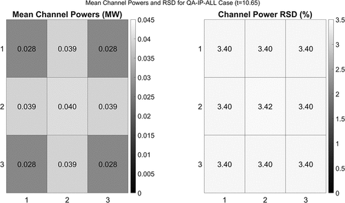
Radial power distributions at the most common peak power time step, 10.65 s, are shown for both cases in and . The effect of manufacturing uncertainties was found to be essentially nonexistent. The axial power distribution at this point is shown in for both cases, where again the impact of manufacturing uncertainties on the power distribution at the transient peak was found to be negligible compared to the impact of nuclear data uncertainties. Pin power factors for the corner and center assemblies are shown for the manufacturing uncertainty case in , where the effect of manufacturing uncertainties on the local pin power factors was again nonnegligible.
IV.C. Final Core State
The state of the PWR mini core was examined at 50 s, 20 s after the completion of control rod movements. The mean core power factor at the end of the simulated period was found to be approximately 1.36, with a RSD of about 1.6% in both cases. In both cases, the null hypothesis of normality was rejected at the 5% significance level.
The radial power distributions for the full-assembly nuclear data case at the end of the simulated period is shown in , with no significant differences observed for the manufacturing uncertainty case. The axial power distribution and its uncertainty are shown for both cases in . Pin power factors for the corner and center assemblies are shown in for the manufacturing uncertainty case. The impact of manufacturing uncertainties relative to nuclear data uncertainties was found to be small at the conclusion of the transient for global parameters, while the local pin power factors were found to be affected by the manufacturing uncertainties in a similar manner to the initial and peak points of the transient.
V. CONCLUSIONS
This work presented results for a subset of the PWR time-dependent neutronics exercises of the UAM-LWR benchmark study. The SCALE code system was used to perform lattice-level calculations of the benchmark PWR fuel assembly in Exercise II-2a, and the PARCS diffusion code was used to study the mini PWR core rod movement transient from Exercise II-2b. For both studies, the importance of both nuclear data uncertainties and manufacturing uncertainties was considered and different modeling approaches were compared.
In the depletion studies of the PWR lattice, it was found that global parameters, such as keff, homogenized cross sections, and the assembly isotopic composition, were more significantly affected by nuclear data uncertainties. Some local parameters, such as the ADFs, diffusion coefficients, and individual pin compositions, were affected by both nuclear data and manufacturing uncertainties. Finally, some local parameters, such as pin power factors, were predominantly affected by manufacturing uncertainties. The effect of tracking isotopic compositions of each pin individually was typically found to be small, with minor effects noted as burnup increased in the ADFs and pin powers.
Correlation coefficients for the homogenized group data were studied over the length of the fuel cycle for each of the cases considered. The most significant effects of manufacturing uncertainties on the correlation coefficients were observed for parameters involving either ADFs or diffusion coefficients. Since the majority of correlation coefficients considered were between global lattice parameters, it was expected that the effect of manufacturing uncertainties would be less prevalent than the effect of nuclear data uncertainties. It was also noted that some correlation coefficients vary significantly with burnup, typically going from having a very weak relationship at BOC to a moderately strong correlation (or anticorrelation) at EOC. Changes in the correlation coefficients were found to occur nonlinearly, with most of the change typically occurring over the first half of the fuel cycle before mostly leveling off over the second half.
Similar to the lattice-level studies, it was found in the mini-core transient studies that global parameters, such as core power, core reactivity, and the radial/axial power distributions, were primarily affected by nuclear data uncertainties. Local parameters, such as the corner and center assembly pin power factors, were found to be more significantly affected by manufacturing uncertainties. Only minor differences in assembly powers, core power, axial power distribution, and reactivity were observed between models at the initial, peak, and final points of the transient. Future work on the PWR transient is required to better account for uncertainty effects in the kinetics factors, such as the delayed neutron fractions and decay constants. Additionally, future work to incorporate the effects of thermal-hydraulic feedback on the PWR transient and to determine the significance of thermal-hydraulic uncertainties relative to nuclear data and manufacturing uncertainties is required.
The results presented in this work demonstrate that while both nuclear data and manufacturing uncertainties have measurable effects on uncertainty in PWR studies, the relative importance of the two depends on whether the parameter of interest is a global or local phenomenon. For most global parameters, nuclear data uncertainties are typically much more significant, while manufacturing uncertainties make only a negligible contribution. For local parameters, manufacturing uncertainties, applied on a pin-by-pin basis, were found to be significant contributors to uncertainty. The additional computational effort required to completely simulate the effect of manufacturing uncertainties was found to be significant, and thus future work should weigh the importance of manufacturing uncertainties on the figures of merit being considered when deciding how to proceed.
Nomenclature
| ADF1 | = | = fast group ADF |
| ADF2 | = | = thermal group ADF |
| D1 | = | = fast group diffusion coefficient |
| D2 | = | = thermal group diffusion coefficient |
| keff | = | = neutron multiplication factor |
Greek
| ∑A1 | = | = fast group absorption cross section |
| ∑A2 | = | = thermal group absorption cross section |
| ν∑f1 | = | = fast group fission cross section multiplied by average number of neutrons per fission |
| ν∑f2 | = | = fast group fission cross section multiplied by average number of neutrons per fission |
| ∑S 1->2 | = | = fast to thermal energy group scatter cross section (i.e., downscatter) |
Acronyms
| ADF | = | = assembly discontinuity factor |
| BOC | = | = beginning of cycle |
| EOC | = | = end of cycle |
| HFP | = | = hot full power |
| HZP | = | = hot zero power |
| LWR | = | = light water reactor |
| MWd/kg | = | = megawatt-days per kilogram of uranium |
| PWR | = | = pressurized water reactor |
| ppm | = | = parts per million |
| RSD | = | = relative standard deviation |
| UAM-LWR | = | = Uncertainty Analysis in Modelling for Light Water Reactors benchmark study |
Acknowledgments
This work was funded by the Natural Sciences and Engineering Research Council of Canada and the University Network of Excellence in Nuclear Engineering.
Disclosure Statement
No potential conflict of interest was reported by the authors.
Notes
a While the work performed in this paper includes some uncertainty in kinetics parameters, which results from differences in nuclear data between trials, the inclusion of uncertainties in the delayed neutron group fractions and precursor decay constants was not available in the official SCALE release at the time of this work.
References
- A. AURES et al., “Reactor Simulations with Nuclear Data Uncertainties,” Nucl. Eng. Des., 355, 110313 (2019); https://doi.org/10.1016/j.nucengdes.2019.110313.
- K. ZENG et al., “Uncertainty Quantification and Propagation of Multiphysics Simulation of the Pressurized Water Reactor Core,” Nucl. Technol., 205, 1618 (2019).
- K. IVANOV et al., “Benchmark for Uncertainty Analysis in Modelling (UAM) for Design, Operation and Safety Analysis of LWRs Volume I: Specification AND Support Data for the Neutronics Cases (Phase I),” Organisation for Economic Co-operation and Development Nuclear Energy Agency (2016).
- J. HOU et al., “Benchmark for Uncertainty Analysis in Modelling (UAM) for Design, Operation and Safety Analysis of LWRs—Volume II: Specifications and Support Data for the Core Cases (Phase II),” Organisation for Economic Co-operation and Development Energy Agency (2017).
- M. L. WILLIAMS et al., “SAMPLER: A Module for Statistical Uncertainty Analysis with SCALE Sequences,” SCALE Code System, pp. 1315–1372, Oak Ridge National Laboratory (2016).
- T. DOWNAR, Y. XU, and V. SEKER, “PARCS v3.0 U.S. NRC Core Neutronics Simulator User Manual,” University of Michigan, Ann Arbor (2013).
- A. WARD, Y. XU, and T. DOWNAR, “GenPMAXS—v6.2 Code for Generating the PARCS Cross Section Interface File PMAXS,” University of Michigan (2016).
- A. AURES et al., “Helios-2/XSUSA Sensitivity and Uncertainty Analyses with ENDF/B-VII.1 Covariance Data,” Ann. Nucl. Energy, 167, 108857 (2022); https://doi.org/10.1016/j.anucene.2021.108857.
- M. I. RADAIDEH, W. A. WIESELQUIST, and T. KOZLOWSKI, “A New Framework for Sampling-Based Uncertainty Quantification of the Six-Group Reactor Kinetic Parameters,” Ann. Nucl. Energy, 127, 1 (2019); https://doi.org/10.1016/j.anucene.2018.11.043.
- A. SARGENI et al., “Uncertainties Propagation in the UAM Numerical Rod Ejection Benchmark,” Ann. Nucl. Energy, 141, 107339 (2020); https://doi.org/10.1016/j.anucene.2020.107339.
- C. MESADO et al., “Uncertainty and Sensitivity of Neutron Kinetic Parameters in the Dynamic Response of a PWR Rod Ejection Accident Coupled Simulation,” Sci. Technol. Nucl. Ins., 2012, 1 (2012); https://doi.org/10.1155/2012/625878.

