
 ?Mathematical formulae have been encoded as MathML and are displayed in this HTML version using MathJax in order to improve their display. Uncheck the box to turn MathJax off. This feature requires Javascript. Click on a formula to zoom.
Abstract
Research on small modular reactors (SMRs) is gaining importance since they are key for addressing energy challenges in various sectors. These types of reactors integrate novel technologies that rely heavily on passive safety systems. Among the most developed light water reactors, SMR designs are SMART and NuScale. This work analyzes the academic boron-free Karlsruhe Small Modular Reactor (KSMR), which may fit in SMART, and a core design resembling NuScale. The research aims to explore the potential of new multiphysics tools under development to predict safety parameters of SMRs during normal operation and transients. For this purpose, the Purdue Advanced Reactor Core Simulator (PARCS) and TWOPORFLOW (TPF) codes have been coupled using the Interface for Code Coupling (ICoCo), orchestrating code execution through a C++ Supervisor program. In this work, a nodewise rod ejection accident (REA) has been analyzed for two different scenarios. The first is a hot-zero-power scenario for the KSMR core, and the second is initiated at 75% of nominal power for the NuScale core. Verification of results has been done though code-to-code comparison. Comparison of the PARCS/TPF results obtained for both KSMR and NuScale with reference cases shows acceptable differences. Key safety parameters predicted by the codes for the REA analysis of both cores have also been evaluated against the latest U.S. Nuclear Regulatory Commission regulation for reactivity initiated accidents showing that all parameters fulfill core coolability acceptance criteria and fuel rod cladding failure thresholds. The presented work highlights the transition from the coupling of PARCS with a mixture model code, such as SCF, to a coupling with a two-phase model code, such as TPF. These findings contribute to a better understanding of SMR phenomenology during accidental sequences and demonstrate the capabilities of the coupled codes.
I. INTRODUCTION
Over the last years, the development of small modular reactors (SMRs) has increased because of their enhanced safety characteristics that rely heavily on the usage of passive systems. In addition, their reduced power output is suitable for different electric grids. SMR designs under development use a variety of coolants and fuel forms with different technology and licensing characteristics.
Currently, there are more than 60 SMR concepts in various stages of development.[Citation1] While a significant portion of SMRs relies on well-established light water reactor (LWR) technology, their smaller cores compared to conventional LWRs present new challenges for core physics simulations. Traditional analysis tools, such as nodal diffusion solvers coupled with one-dimensional (1D) thermal-hydraulic (TH) codes, may not be fully suited to address these challenges.[Citation2,Citation3]
Researchers worldwide are actively investigating the applicability of high-order neutron physics codes and TH codes with increased space resolution to ensure accurate modeling of SMR phenomena.[Citation2] This exploration aims to enhance the understanding of and simulation capabilities for SMRs, acknowledging their unique characteristics and requirements. Multiphysics three-dimensional (3D) core simulations based on 3D nodal solvers and 3D TH methods such as subchannel codes make feasible the accurate prediction of local feedback between neutronic and TH phenomena and are of great importance in reactor design and safety.
Several code coupling approaches exist for 3D methodologies for the research community to utilize, e.g., reactivity initiated accident (RIA) analysis.[Citation4] One of the most flexible and modular methods for code coupling is based on the Interface for Code Coupling[Citation5] (ICoCo). Other methods are the Virtual Environment for Reactor Applications[Citation6] (VERA), the Multiphysics Object-Oriented Simulation Environment[Citation7] (MOOSE), and the Kraken[Citation8] framework based on socket communication. An external coupling approach allows modular independency and reusability. Contrary to it, coupling interfaces optimize the data transfer between the coupled codes, overcoming the previous need for disk read-write operations.
On the industry side, classical RIA analysis is based mainly on 1D methodologies. For example, Westinghouse Electric Company is using 1D kinetics (the TWINKLE code for neutronics and the FACTRAN code for a fuel rod), which is referred to as WCAP-7588.[Citation9] Later developments aim to use 3D methodologies.[Citation3] For example, in 2003, Westinghouse adopted a new methodology, WCAP-15807-NP-A,[Citation10] based on the SPONOVA 3D solver and the VIPRE subchannel code.
For the NuScale RIA analysis, the SIMULATE-3K code is used in connection with RELAP5 to simulate the integral plant behavior under transients. The departure from nucleate boiling ratio (DNBR) is predicted by the VIPRE-01 subchannel code using the NSP4 correlation with 1.284 as the safety limit (SL).[Citation11,Citation12] It is worth noting that in this methodology, fuel cladding failure is not allowed, so the cladding failure thresholds become acceptance criteria. This differs from Regulatory Guide 1.236 (RG 1.236),[Citation13] where cladding failure is allowed as long as the released dose meets the acceptance criteria.
On the other hand, Korea Atomic Energy Research Institute has developed the TASS/SMR-S code[Citation14–16] for the safety analysis of SMART100, where a 1D TH analysis of the core is done to predict the minimum DNBR and the cladding temperature.
In this research, the ICoCo framework has been employed to couple the reactor core Purdue Advanced Reactor Core Simulator (PARCS) and the porous-medium two-phase flow code TWOPORFLOW (TPF). This approach not only simplifies the integration process but also enhances the efficiency of data transfer between these codes, streamlining the research efforts.
The transient selected for analysis in this work is a rod ejection accident (REA), which is a design-basis RIA. The REA is initiated by failure of the housing in the upper head of the reactor vessel where the control rod (CR) drive mechanism attaches. The initial power level affects both the ejected rod worth and the Doppler feedback, two of the most critical parameters that determine the power evolution. The fast ejection of a CR causes a sharp increase in reactivity in the core, increasing core power peaking around the location of the ejected rod. This type of transient should be analyzed with a multiphysics tool because of the strong reactivity feedbacks between neutronics and thermal hydraulics. Moreover, since the rod ejection can occur at any CR position, it is desired to use 3D simulation tools that can identify the location of hot spots during the transient evolution. The power excursion may lead to failure of the first safety barrier, i.e., fuel cladding, and may release radioactive material to the coolant.
The present study analyzes a REA in two reactor cores designed to resemble well-established SMR designs, each representing a different approach to nuclear technology development.[Citation17,Citation18] The first reactor core model, the Karlsruhe Small Modular Reactor (KSMR), is an academic core developed at Karlsruhe Institute of Technology (KIT) for beginning-of-life (BOL) conditions that may fit in the SMART core.[Citation19] The second reactor core model, the NuScale core, for BOL conditions is based on publicly available information from the NuScale SMR, developed in the United States.[Citation20]
This paper is structured as follows. Section II provides an overview of the regulatory guidelines for RIA, and Sec. III presents the methodology applied in the study. This is followed in Sec. IV by a detailed description of the SMR core models studied. Section V defines the two REA transients analyzed. Selected results are then discussed in Sec. VI. Finally, Sec. VII provides the conclusions, summarizes the main findings, and provides future research directions.
II. REGULATION APPLIED TO RIA ANALYSIS
This section reviews the status of the U.S. Nuclear Regulatory Commission (NRC) regulations for RIA in pressurized water reactors (PWRs). The objective is to gain an understanding of the NRC acceptance criteria for REA accidents. Then, the results obtained with the PARCS/TPF multiphysics approach for REA analysis can be compared to the new acceptance criteria.
In Regulatory Guide 1.77,[Citation21] the NRC provided the first guidance for PWR RIA accidents. However, since its publication in 1974, there have been significant improvements in the comprehension of fuel rod behavior in the event of prompt power excursions. Therefore, this regulation has been updated over the years.
In 2007, the NRC stablished interim acceptance criteria and guidance in NUREG-0800, “Standard Review Plan,” Rev. 3, Sec. 15.4.8.[Citation22] The basis for the revision was provided in the NRC Memorandum, “Technical and Regulatory Basis for the Reactivity-Initiated Accident Interim Acceptance Criteria and Guidance.”[Citation23] Later, the status of knowledge, e.g., new empirical data and new analysis, changed so that the NRC identified further modifications to the RIA accident guidance in the NRC Memorandum, “Technical and Regulatory Basis for the Reactivity-Initiated Accident Acceptance Criteria and Guidance.”[Citation24]
Finally, in 2020, after a thorough reassessment of the conclusions drawn from new evaluations, experiments, and data, the NRC published a new version of the regulatory guide. There, the acceptance criteria for the PWR REA included in RG 1.236[Citation13] are related to reactor coolant system (RCS) pressure, core coolability, and the dose emitted by the RIA. The limits set for these acceptance criteria are summarized as follows:
Core coolability: To ensure that any time the geometry of the core does not block the coolant flow, the peak radial average enthalpy cannot exceed 230 cal/g. It is also stated as an acceptance criterion that a maximum of 10% of the total volume of the melting fuel can be present.
RCS pressure: The RCS pressure cannot exceed 120% of the design pressure. This is the limit value to prevent the stresses from surpassing the emergency condition (Service Level C).
Radiological consequences: The radiological consequences are included in Regulatory Guide 1.183[Citation25] and Regulatory Guide 1.195.[Citation26]
The radiological consequences are directly related to the fission product released due to the cladding failure. Therefore, the fuel rod cladding failure thresholds are considered in the RIA analysis. To know the total number of failed fuel rods and to ensure that the radioactive dose does not exceed the limits, RG 1.236 establishes the following thresholds for the different cladding failure modes:
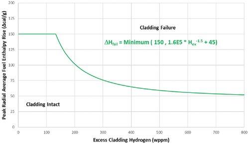
High temperature: Two different criteria apply depending on the reactivity value associated to the CR ejection. If the reactivity exceeds 1 $, it is considered to be a prompt-critical excursion. For this case, the peak radial average enthalpy limit is a function of the fuel cladding differential pressure; see . Otherwise, for non-prompt-critical excursion, the fuel is assumed to fail if the DNBR limits are exceeded in PWRs [or the critical power ratio limit in boiling water reactors (BWRs)].
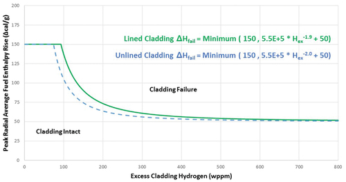
Pellet-cladding mechanical interaction (PCMI): This criterion is a function of the excess cladding hydrogen content. Different functions are provided depending on whether the cladding is stress-relieved anneal (SRA) or recrystallization anneal (RXA), as well as on whether the cladding temperature is above or below 260°C; see through .
Molten fuel: If the fuel temperature exceeds the fuel melting temperature at any location of the pellet, fuel cladding failure is assumed.
Fig. 1. High-temperature cladding failure (reactivity > 1 $).
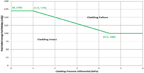
Fig. 2. PCMI cladding failure (RXA cladding and Tcladding > 260°C).
A summary of the NRC guidance evolution for RIA is provided in . It is noteworthy that the nuclear regulatory bodies in different countries set different values for the acceptance criteria and fuel rod cladding failure thresholds listed in this section, or even set different parameters such as the average burnup limit per fuel assembly (FA).[Citation3,Citation27,Citation28] On the other hand, design companies also set their own limits and acceptance criteria for RIA-related safety analysis. Sometimes, the industry limits are more restrictive than the regulatory ones, as is the case for Westinghouse (WCAP-7588 in 1975 and WCAP-15807-NP-A in 2003)[Citation9,10] and NuScale (TR-0716-50350 in 2020, updated in 2023).[Citation11,Citation12,Citation29]
TABLE I Evolution of the NRC Guidance for PWR RIA
Fig. 3. PCMI cladding failure (SRA cladding and Tcladding > 260°C).
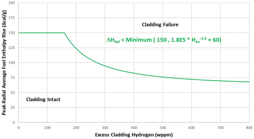
Fig. 4. PCMI cladding failure (RXA cladding and Tcladding < 260°C).
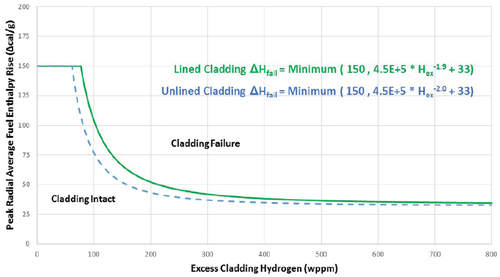
Fig. 5. PCMI cladding failure (SRA cladding and Tcladding < 260°C).
III. EXTERNAL COUPLING METHODOLOGY
At KIT, extensive experience has been accumulated in utilizing the ICoCo framework for the development of both multiphysics and multiscale couplings. Notable couplings achieved under the ICoCo framework include
Serpent2/SCF/TRANSURANUS[30]
TRACE/SCF[Citation31]
PARCS/SCF.[Citation32]
The following sections describe the PARCS code, the TPF code, and the interface and coupling scheme used in the analysis.
III.A. Nodal Neutron Diffusion Code PARCS
PARCS is a 3D reactor core simulator, which solves the steady-state and time-dependent multigroup neutron diffusion or low-order neutron transport equations in Cartesian or hexagonal fuel geometries. PARCS, as a stand-alone code, includes both a simple single-phase TH fluid model, which may be adequate for PWR analysis, and a two-phase TH model called PARCS Advanced TH Solver (PATHS), which may be appropriate for BWR analysis. For models that require more sophisticated modeling of the TH system behavior, PARCS can be coupled with an external TH system analysis code.[Citation33]
III.B. Thermal-Hydraulic, Porous-Medium, Two-Phase Flow TPF Code
TWOPORLOW is a TH simulation code currently under development at KIT. It has the capability to simulate single- and two-phase flow in a porous medium using a 3D Cartesian geometry. The code represents solid structures, such as fuel rods, like blocking volumes and areas. Face and volume porosities are used to calculate convection and diffusion of momentum by applying the Fractional Area Volume Obstacle Representation (FAVOR) technique.[Citation34] A velocity vector related to the porosity is defined as
where subscripts = Cartesian coordinates;
= fluid phase. Equations containing this information are analogous to the equations for flow in porous media.
TPF calculates the steady-state and transient solution of the mass, momentum, and energy conservation equations for each fluid phase with a semi-implicit numerical procedure based on the implicit continuous Eulerian approach.[Citation35,Citation36]
To predict heat transfer on the fuel rod surface, the Gnielinski[Citation37] correlation is employed while the Westinghouse-3 (W-3) correlation is used for predicting the critical heat flux. TPF uses internal material correlations and properties, including conductivity, specific heat, density, emissivity, and thermal expansion.
III.C. Interface for Code Coupling
ICoCo is written in C++ and defines mother classes that control each code. ICoCo defines methods for a common mother class named “Problem,” which facilitate initialization, time advancement, saving and restoring, and field exchange.[Citation5] presents the ICoCo methods implemented in PARCS and TPF.
TABLE II ICoCo Methods Implemented in PARCS and TPF
To implement ICoCo in a code, two major requirements must be complied with. The first one is a high modularization of the code, and the second is a compulsory MED format mesh. Data field interpolation is performed using MEDCoupling library functions. A C++ Supervisor program carries out the execution of codes and data manipulation.[Citation30]
III.D. PARCS/TPF Coupling Scheme
In a two-way coupling scheme, the neutronics code PARCS and the TH code TPF collaborate synergistically to enhance the accuracy and fidelity of reactor simulations. This coupling is essential for capturing the close relation between neutronics and TH phenomena within the reactor core.
In this scheme, PARCS takes on the role of providing a detailed 3D power distribution map. Unlike stand-alone TH traditional approaches that rely on simplified radial and axial power profiles, PARCS offers a more precise and spatially resolved power distribution. This enhanced power distribution serves as input to the TPF code.
On the other hand, TPF computes 3D distributions of key parameters, including fuel temperature, coolant temperature, and coolant density for each phase. These distributions play a crucial role in predicting local safety parameters such as DNBR, fuel enthalpy, fuel centerline temperature, cladding outer surface temperature, and coolant temperature.
The exchange of data between PARCS and TPF is achieved through a domain overlapping nodewise feedback mechanism. This mechanism allows for seamless communication between the two codes, ensuring that the most up-to-date information is utilized during each iteration of the simulation. A visual representation of the iterative process that underlies the PARCS/TPF coupled calculations is shown in .
Fig. 6. PARCS/TPF coupling iterative scheme.
IV. DEVELOPED SMR CORE MODELS FOR THE RIA ANALYSIS
In this section, a short description of two SMR core designs selected for the RIA analysis, i.e., KSMR and NuScale, is provided. Subsequently, the models developed for the neutronic (PARCS) and TH (TPF) analysis are described.
IV.A. Boron-Free KSMR Core
The boron-free KSMR core is an academic core design for BOL that fits into the SMART reactor.[Citation19] The core’s basic FA design follows standard PWR technology with a 17×17 fuel rod array, 24 guide tubes, and a central instrumentation tube. To address its boron-free concept, FAs are designed with fixed burnable poison (BP) rods (20 or 24) to manage excess reactivity at BOL using Al2O3 mixed with B4C. Fuel rods contain UO2 enriched with less than 5% and SRA Zircaloy-4 claddings.[Citation38]
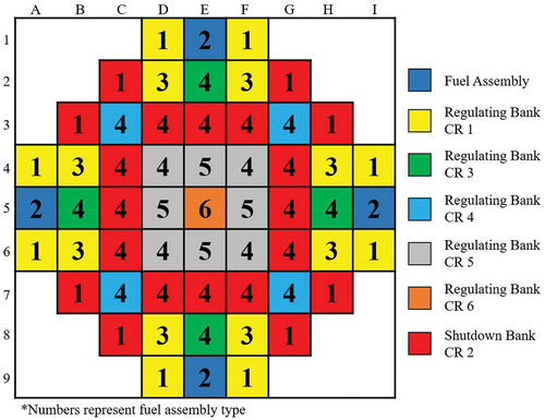
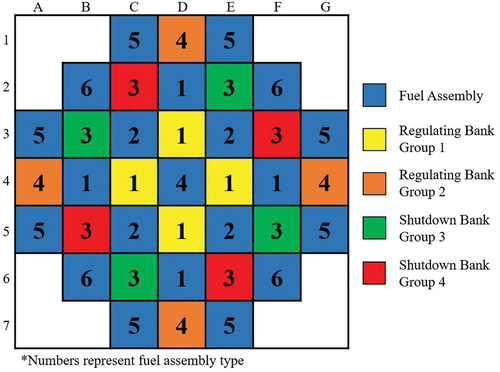
The KSMR core comprises 57 FAs of six types, featuring radial and axial enrichment and BP variations, shown in . The core includes 53 rodded FAs, organized into regulating banks (RBs) and a safety shutdown bank (SB). The RBs consist of 33 CRs with 16 Ag-In-Cd (AIC) and 17 hybrid CRs. The SB consists of 20 CRs made of B4C. The FA types and CR positions are shown in while the nominal operating conditions are given in .
TABLE III KSMR Fuel Assembly Enrichment
TABLE IV KSMR Nominal Operation Core Parameters
Fig. 7. KSMR FAs and CR layout.
IV.A.1. Neutronic PARCS Model of the KSMR Core
The PARCS neutronic model for the KMSR core was adopted from previous studies conducted in the framework of the McSAFER project,[Citation2] where the hybrid nodal kernel was used. As presented by Alzaben[Citation19] and Mercatali et al.,[Citation32] for the fresh core, in total, 32 different material compositions are used for FAs and reflectors in the KSMR core. For each material composition, two-group nodal cross sections (energy cut set at 0.625 eV) were generated using the Serpent2 code. These cross sections consider a range of temperatures, from 26.85°C to 1826.85°C for fuel temperature, and from 26.85°C to 341.85°C for coolant temperature. Group constants were generated for both rodded and unrodded cases.
The KSMR core geometry is represented in PARCS with an 11×11 radial grid, 9×9 representing the active part, and 22 axial levels. Among these levels, 20 represent the active core while 1 is dedicated to each of the lower and upper reflectors. A PARCS homogenized cell model mesh for one FA can be seen in . The mesh cell size measures 21.5 × 21.5 × 10.0 cm, with an active length of 2.0 m. The bottom reflector has a length of 36.31 cm, and the top reflector extends to 49.92 cm.
Fig. 8. KSMR FA spatial homogenization in PARCS code.
IV.A.2. Thermal-Hydraulic TPF Model of the KSMR Core
The TH core model for the KSMR design utilizes data from Alzaben[Citation19] to create representations for both FAs and coolant within the porous-medium code. The core is discretized into a 9×9 radial mesh grid with 20 axial levels, matching the PARCS neutronic model. Mesh cells measure 21.5 × 21.5 × 10.0 cm, with an active length of 2.0 m. Each FA is represented using a 3D Cartesian mesh, considering all 289 rods through a representative rod-centered subchannel, as shown in .
Fig. 9. KSMR assembly-wise fuel centered channel representation in TPF code.
TPF requires data for each 3D cell, including porosity and key geometric parameters essential for TH calculations, such as hydraulic diameter. These values, calculated based on the geometric data of 264 fuel rods and 25 guide tubes, are summarized in .
TABLE V KSMR FA Geometrical Parameters for TPF
For the heat conduction solver, representative fuel rods are divided radially into nine concentric zones: six zones within the pellet with radii of 0.0, 7.8436E-04, 1.5687E-03, 2.3530E-03, 3.1374E-03, and 3.9218E-03 m; one zone for the gap with external radius of 3.9987E-03 m; and two zones within the cladding with radii of 4.2844E-03 and 4.5702E-03 m. Porosities in the X and Y directions were calculated using 12 fuel rods and 5 guide tubes, while the Z-direction porosity was calculated with 264 fuel rods and 25 guide tubes.
IV.B. NuScale Core
The NuScale[Citation20] SMR is an integral PWR design with natural circulation and passive safety systems for efficient heat removal from the core. The NuScale core in this study was based on publicly available information from NuScale[Citation18] and the benchmark definitions by Fridman et al.[Citation39]
The NuScale FA is a 17×17 design, half the length of conventional PWR fuel, with UO2 fuel rods enriched with less than 5% and RXA M5 cladding material.[Citation38,Citation40] As shows, the core comprises 37 FAs, including 16 assemblies hosting CRs organized into RBs and SBs, each with 8 rodded FAs. The core has six types of FAs, featuring enrichment variations, shown in . The CRs use a combination of AIC and B4C as absorber materials. outlines the nominal operational conditions for the NuScale reactor.
TABLE VI NuScale Fuel Assembly Enrichment
TABLE VII NuScale Nominal Operation Core Parameters
Fig. 10. NuScale FAs and CR layout.
IV.B.1. Neutronic PARCS Model of the NuScale Core
The PARCS neutronic model for NuScale was developed in collaboration with the Universidad Politécnica de Madrid research group, a partner in the McSAFER project,[Citation41] where the hybrid nodal kernel was used. The VTT research group, also within McSAFER, generated cross sections with the Serpent2 code using the library ENDF/B-VII.1, following Fridman et al. benchmark definitions.[Citation39]
This effort resulted in 14 different material compositions for FAs and reflectors in the NuScale core. For each composition, two-group nodal cross sections were generated, with the two-group energy cut being 0.625 eV. Considering a range of conditions, fuel temperature was from 773.15°C to 2073.15°C, coolant density was from 0.3 to 0.9 g/cm3, and coolant poison concentration was from 0 to 2000 ppm. Group constants were calculated for rodded and unrodded cases.
In PARCS, the NuScale core is represented with a 9×9 radial grid, 7×7 representing the active part, and 22 axial levels. Of these, 20 represent the active core, with one each for the lower and upper reflectors. As shows, the PARCS homogenized cell model mesh for a FA has a cell size of 21.5 × 21.5 × 10.0 cm and an active length of 2.0 m. The bottom reflector extends to 11.62 cm while the top reflector reaches 27.13 cm.
Fig. 11. NuScale FA spatial homogenization in PARCS code.

IV.B.2. Thermal-Hydraulic TPF Model of the NuScale Core
The TH core model for the NuScale design incorporates data from Fridman et al.[Citation39] for both FAs and coolant, within the porous-medium code. The core is discretized into a 7×7 radial mesh grid with 20 axial levels, matching the dimensions of the PARCS neutronic model. Mesh cells have dimensions of 21.5 × 21.5 × 10.0 cm, with an active length of 2.0 m. Each FA is represented using a 3D Cartesian mesh, encompassing all 289 rods through a representative rod-centered subchannel; see . For the heat conduction solver, representative fuel rods are divided radially into nine concentric zones: six zones within the pellet with radii of 0.0, 8.1153-04, 1.6230E-03, 2.4345E-03, 3.2461E-03, and 4.0576E-03 m; one zone for the gap with external radius of 4.1402E-03 m; and two zones within the cladding with radii of 4.445E-03 and 4.7498E-03 m. Key TH data for each 3D cell are summarized in , derived from geometric data for 264 fuel rods, 24 guide tubes, and 1 instrumentation tube. Porosities in the X and Y directions were calculated using 12 fuel rods and 5 guide tubes, while the Z-direction porosity was calculated with 264 fuel rods and 25 guide tubes.
TABLE VIII NuScale FA Geometrical Parameters for TPF
Fig. 12. NuScale assembly-wise fuel centered channel representation in TPF code.
V. REA TRANSIENT DEFINITION
Following the description of the cores of the two SMRs (KSMR and NuScale) in the previous section, the aim of Sec. V is to describe the key parameters of the REA transient scenarios. The boundary and initial conditions are also given.
V.A. KSMR REA
The key parameters for the KSMR core REA transient are summarized in , and the initial and boundary conditions are summarized in . The analysis starts from the hot-zero-power (HZP) state, which represents the most challenging scenario.[Citation42] In the initial CR configuration for criticality, all RBs are fully inserted while SB is fully extracted. The CR with the highest worth is at position D8 (see ). This analysis assumes no SCRAM, but in case it would, a CR insertion time is approximately 2 s, which significantly exceeds the power excursion duration.
TABLE IX Calculation Parameters for KSMR REA
TABLE X Initial and Boundary Conditions for KSMR REA
The acceptance criteria of RG 1.236 to be applied, which are independent of the RIA parameters, are the following:
Peak radial average fuel enthalpy < 230 cal/g.
Maximum of 10% of the fuel can reach the melting temperature.
RCS pressure does not exceed 120%.
The fuel rod cladding failure thresholds in RG 1.236 due to high cladding temperature depend on the reactivity due to REA. As the highest CR worth is 1.4839 $, greater than 139 $, the thresholds to be considered correspond to those shown in (minimum value 100 cal/g). Besides, the fuel failure by PCMI depends on the cladding type and its initial temperature. Since the cladding type for the KSMR fuel is SRA and its initial temperature is higher than 260°C, the thresholds to be evaluated are those shown in (minimum value 70 cal/g).
V.B. NuScale REA
The NuScale REA parameters and initial conditions are summarized in and . The selected scenario considers ejection of a single regulating CR at 75% of nominal power. This scenario has been selected based on the results of the REA analysis in the NuScale Design Certification Application (DCA), Chap. 15, where it can be observed that the maximum radial average fuel enthalpy occurs when the NuScale initial power is between 70% and 80%.[Citation11] The CR position that leads to a critical state at the selected conditions is with all CRs fully extracted, except for RB2, which is 56% withdrawn.[Citation20]
TABLE XI Calculation Parameters for NuScale REA
TABLE XII Initial and Boundary Conditions for NuScale REA
The sequence of events in this transient is as follows:
At t ≤ 0.0 s, the system is made critical at the core state and power level specified for the transient scenario.
At 0.0 s ≤ t ≤ 0.1 s, the CR at position A4 (see ) is ejected from the core at constant speed within 0.1 s.
At 0.1 s ≤ t ≤ 2.0 s, transient evolution without external changes is applied to the system, pure reactivity feedback interaction.
At s ≤ t ≤ 3.0 s, the CRs are inserted at constant speed within 1.0 s, and all rods are inserted except for A4 (ejected) and B5 (stuck).
At s ≤ t ≤ 4.0s, transient evolution without external changes is applied to the system.
Since they are independent of the RIA parameters, the RG 1.236 acceptance criteria to be applied are those commented for KSMR.With regard to the fuel rod cladding failure threshold, the highest CR worth is less than 1 $, so the parameter to consider for high cladding temperature failure is the departure from nucleate boiling (DNB) limit. On the other hand, the cladding type for NuScale fuel is RXA, and the initial cladding temperature distribution is higher than 260°C at any radial and axial location because the coolant inlet temperature is 262°C. Therefore, the thresholds to be met for the maximum fuel enthalpy rise are shown in (the minimum threshold value is 50 cal/g).
VI. RESULTS AND DISCUSSION
In this section, the selected results from the REA transient analysis, conducted for the first time with PARCS/TPF, are compared with those calculated by PARCS/SCF[Citation32,Citation42] for the KSMR core and with ANTS/SCF[Citation43,Citation44] for the NuScale core. The comparison includes maximum values for power, reactivity insertion, fuel temperature, cladding temperature, and the minimum DNBR to verify the results obtained with PARCS/TPF. In each of , and , both coupling results, the reference ones and those obtained in the analysis, are shown.
Fig. 13. KSMR REA global power evolution.
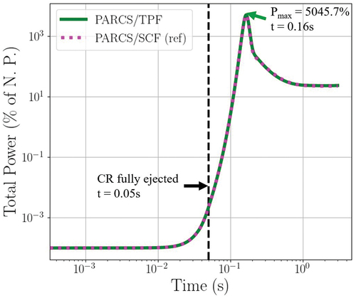
Fig. 14. KSMR REA total reactivity evolution.
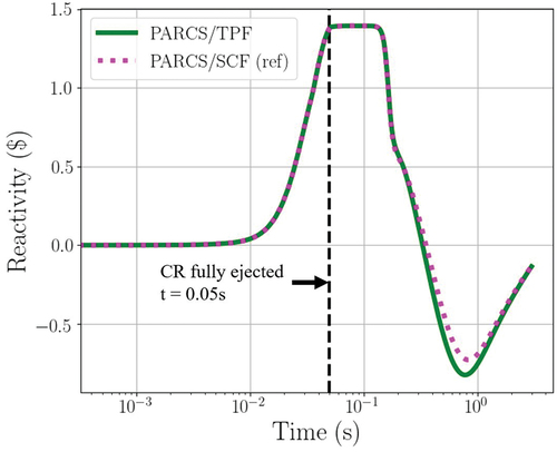
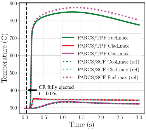
Fig. 15. KSMR REA maximum temperature evolution.
VI.A. KSMR REA Analysis
For the KSMR core, the global power evolution and total reactivity during the transient were obtained. A peaking value of 5045% of nominal power was reached at 0.16 s. This power excursion lasted less than 0.2 s (see ) because of a fast insertion of −2.2 $, led by the Doppler reactivity feedback (see ) until reaching about 20% of the nominal power at the end of the transient calculation. Maximum fuel, cladding, and coolant temperatures were also analyzed; see . A fast increase of 550°C in the maximum fuel temperature can be seen; also, the maximum cladding temperature has a fast increase of 55°C, and the maximum coolant temperature has a slow increase of 38°C.
It should be noted that the system is not initially critical; therefore, PARCS normalized the fission source at the beginning of the transient calculations. In consequence, the reactivity at the beginning of the transient is zero. The difference in total reactivity, observed in , is due to a different moderator density reactivity feedback. This reactivity effect is driven by the different mass flow distribution predicted by each code.
On the other hand, the code-to-code comparison of the evolution of global parameters, e.g., total power and reactivity predicted by PARCS/TPF and PARCS/SCF, indicates good agreement. presents selected parameters, revealing that all values exhibit a relative difference of less than 10%, and only small differences are found in the fuel and cladding temperatures.
TABLE XIII KSMR REA Compared Results
An evaluation of the core damage coolability acceptance criteria established by RG 1.236 has been done; see . The RCS pressure and dose rate evaluation are beyond the scope of this work since different kinds of simulations are needed. The radial average hfuel (see dashed line in ) reaches a peak value of 50.39 cal/g, which is well below 230 cal/g; the maximum occurs just after the maximum power is reached at 0.16 s. No fuel melting is predicted during the transient, meeting the acceptance criteria of <10% fuel volume. Therefore, it can be stated that the values obtained fulfill the core damage coolability acceptance criteria.
TABLE XIV KSMR RIA Acceptance Criteria, Cladding Failure Thresholds, and PARCS/TPF Results
Fig. 16. KSMR safety parameters followed during the REA (left) and 3D maximum power distribution (right).
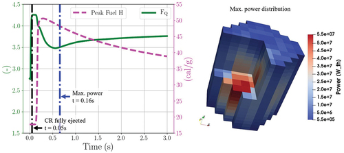
Then, the fuel rod cladding thresholds are evaluated. Since this is a prompt-critical excursion (reactivity > 139 $), RG 1.263 establishes a minimum value of 100 cal/g for the radial average hfuel, which is well met by PARCS/TPF calculations; see dashed line in . Moreover, RG 1.263 establishes a minimum value for the maximum hfuel rise of 70 cal/g for SRA fuel at temperature above 260°C. The maximum hfuel rise calculated with PARCS/TPF is about 49 cal/g.
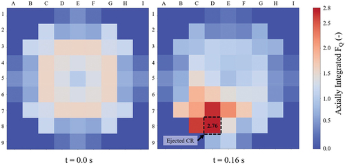
Last, the power peaking is displayed in the solid line of , which shows that 3D approaches are able to calculate a time-dependent FQ, as opposed to 1D methodologies where the FQ is fixed. Additionally, shows the axially integrated radial power peaking factor at the beginning of the transient and at the time where the peak power is observed. It must be noted that the applied coupled codes using 3D nodal diffusion solvers and subchannel thermal hydraulics are able to predict the peak power at the ejected CR position, as expected.
Fig. 17. KSMR axially integrated radial power peaking factor at beginning of the transient (left) and at the power peak (right).
VI.B. NuScale REA Analysis
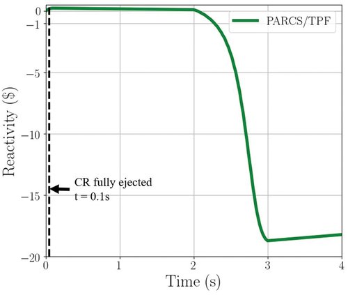
Similar to the KSMR case, the global power was followed along the transient. The reactivity insertion due to the rod ejection is 167.69 pcm, which is less than 1 $, so a slow power increase of 30% is driven, reaching maximum power at 0.66 s. The power is reduced up to 100% of the nominal power by Doppler reactivity feedback. Afterward, SCRAM occurs 2 s after the beginning of the REA, so that after 3 s, the power is reduced to less than 5% of the nominal power. The power and reactivity evolution are shown in and , respectively.
Fig. 18. NuScale REA global power evolution.
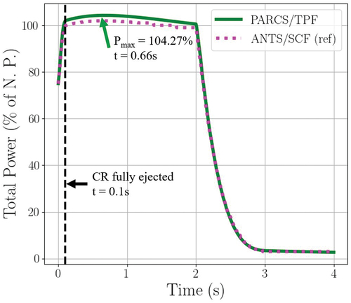
Fig. 19. NuScale REA total reactivity evolution.
Selected parameters of the transient predicted by PARCS/TPF are compared with the ones predicted by ANTS/SCF within the McSAFER project. presents selected maximum and minimum parameter values, revealing that the relative differences between them are less than 5%. The observed discrepancy in the initial critical boron concentration could be related to the differences in the energy groups used for generating nuclear cross sections. It should be noted that the solution from PARCS/TPF is node-averaged without pin-power reconstruction whereas the solution from ANTS/SCF is pin-wise with pin-power reconstruction. Therefore, a comparison of local maximum fuel temperatures is not presented. Nevertheless, displays the maximum fuel and cladding temperature evolution obtained with PARCS/TPF.
TABLE XV NuScale REA Compared Results
Fig. 20. NuScale REA maximum temperature evolution.
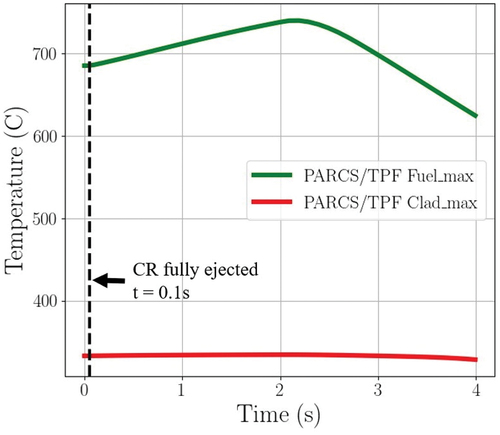
Since the present analysis focuses on RIA core behavior, the results obtained from PARCS-TPF can be compared with the core damage coolability acceptance criteria to determine whether it meets them. To know whether the RIA meets the RCS pressure or the dose acceptance criteria, it would be necessary to involve other types of simulation codes. The radial average hfuel reaches a maximum value of 39.66 cal/g, just after SCRAM, well below 230 cal/g; see dashed line in . Regarding the fuel temperature, the maximum fuel temperature obtained is 740.13°C, which is also well below the melting temperature. Therefore, it can be stated that the values obtained fulfill the core damage coolability acceptance criteria.
Fig. 21. NuScale safety parameters followed during the REA (left) and 3D maximum power distribution (right).
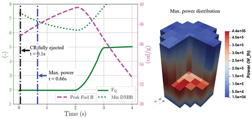
In addition, it has also been analyzed whether the fuel rod cladding failure thresholds are excessive. The value obtained for the radial average hfuel rise, about 2.5 cal/g, is far from the minimum value established by RG 1.236 for RXA fuel at a temperature above 260°C, 50 cal/g, . On the other hand, the minimum DNBR is 6.16, which is significantly below the limit value of 1.3 (W-3); see dotted line in . It should be noted that the DNBR limit applied in the NuScale approach corresponds to the NSP4 correlation, which is not publicly available. As a conclusion, it can be said that according to the results obtained with PARCS/TPF, there is no fuel cladding failure.
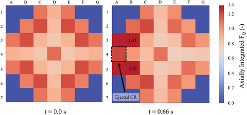
Moreover, the power peaking FQ, which is also time dependent as in the KSMR analysis, has been obtained; see the solid line in . Complementarily, shows the axially integrated radial power peaking factor at the beginning of the transient and at the time where the peak power is observed. It must be noted that the coupled codes based on the 3D nodal diffusion solvers used in this analysis are able to predict strong local perturbations of the power caused, e.g., by the ejection of a CR and shifting the peak value around the ejected CR.
Fig. 22. NuScale axially integrated radial power peaking factor at beginning of the transient (left) and at the power peak (right).
On the other hand, the values obtained in the RIA analysis in the NuScale DCA[Citation11] are shown in column 5, . It is important to note that deterministic safety analyses are bounding analyses with a high degree of conservatism, both in the hypotheses adopted and in the methodologies used. On the other hand, the analysis performed with the TPF/PARCS codes is a best estimate analysis; therefore, significant differences and larger safety margins are obtained.
TABLE XVI NuScale RIA Acceptance Criteria, Cladding Failure Thresholds, and PARCS/TPF Results
VI.C. Computational Loads
An important aspect for industrial use of coupled codes with 3D solvers and subchannel thermal hydraulics is the needed computational effort for RIA analysis. compares the simulations done with PARCS/TPF for both cases and the reference PARCS/SCF simulation. For the KSMR REA transient, the run time is shorter for PARCS/TPF, and the memory usage is the same. Having a better TH modeling does not translate into a more expensive simulation using this coupled system. The speed efficiency of PARCS/TPF is demonstrated to be a fast-running tool. The improvement of the PARCS/TPF calculation time could be related to the fact that SCF needs two MED meshes for data transfer, one for the coolant and one for the fuel. Contrarily, TPF needs just one. The data management among these meshes contributes to the improvement of the overall calculation time for PARCS/TPF. Both KSMR coupled calculations were simulated in a server with an AMD EPYC 7542 CPU; the execution of the coupled code was serial.
TABLE XVII Code Performance Comparison (KSMR Case)
VII. CONCLUSIONS AND OUTLOOK
The PARCS/TPF multiphysics coupling system has been successfully developed at KIT. In this work, a REA analysis has been performed for two SMR designs: KSMR and NuScale. The following conclusions can be drawn from this work:
The presented work highlights the transition from the coupling of PARCS with a mixture model code, such as SCF, to coupling with a two-phase model code, such as TPF. This transition allows a better TH description.
The accuracy and reliability of the PARCS/TPF code have been verified by means of extensive code-to-code comparisons. The results revealed good agreement of the PARCS/TPF predictions compared with those of the reference solutions.
The TPF competitiveness in CPU time paves the way for further applications of this code, e.g., exploration of pin/subchannel level analysis of SMR cores for which purpose TPF will be coupled to a transport solver under development at KIT, named “PARAFISH.” This improvement will allow the prediction of local safety parameters with greater accuracy for SMR.
In this work, the first verification steps for PARCS/TPF results were presented. In the future, a validation procedure for this new tool will be conducted. Subsequent analyses could incorporate calculations with uncertainties in both neutronic and TH parameters, although such analyses were beyond the scope of this work. As presented, the couple code PARCS/TPF is currently developed only for LWRs. One interesting topic for further development involves analyzing reactor technologies other than LWRs, given that TPF has the potential to simulate different working fluids.
Acknowledgments
The authors thank the HGF Program NUSAFE and the BMBF Innovation Pool SMR Initiative for financial support.
The McSAFER project has received funding from the Euratom research and training programme 2019–2020 under the grant agreement number 945063. The content of this paper reflects only the authors views, and the European Commission is not responsible for any use that may be made of the information it contains.
The authors also appreciate the technical collaboration of VTT Technical Research Centre of Finland.
Disclosure Statement
The author(s) reported no potential conflict of interest.
Additional information
Funding
References
- “Small Modular Reactors: Challenges and Opportunities,” Organisation for Economic Co-operation and Development, Nuclear Energy Agency (2021).
- V. SANCHEZ-ESPINOZA et al., “The H2020 McSAFER Project: Main Goals, Technical Work Program, and Status,” Energies, 14, 6348 (2021); http://dx.doi.org/10.3390/en14196348.
- “State-of-the-Art Report on Nuclear Fuel Behaviour Under Reactivity-Initiated Accident Conditions,” NEA No. 7575, Organisation for Economic Co-operation and Development, Nuclear Energy Agency (2022).
- K. L. ZHANG, “The Multiscale Thermal-Hydraulic Simulation for Nuclear Reactors: A Classification of the Coupling Approaches and a Review of the Coupled Codes,” Int. J. Energy Res. (2020); http://dx.doi.org/10.1002/er.5111.
- E. DEVILLE and F. PERDU, “Documentation of the Interface of Code Coupling: ICoCo,” DEN/DANS/DM2S/STMF/LMES/RT/12-029/A, CEA (2012).
- J. A. TURNER et al., “The Virtual Environment for Reactor Applications (VERA): Design and Architecture,” J. Comput. Phys., 26, 544 (Dec. 1, 2016); http://dx.doi.org/10.1016/j.jcp.2016.09.003.
- E. SHEMON et al., “MOOSE Framework Meshing Enhancements to Support Reactor Analysis,” ANL/NSE-21/43, Argonne National Laboratory (2021); https://www.osti.gov/biblio/1821454.
- J. LEPPÄNEN et al., “Current Status and On-Going Development of VTT’s Kraken Core Physics Computational Framework,” Energies, 15, 3, 876 (2022); http://dx.doi.org/10.3390/en15030876.
- D. H. RISHER, “An Evaluation of the Rod Ejection Accident in Westinghouse Pressurized Water Reactors Using Spatial Kinetics Methods,” WCAP-7588, Rev. 1A, Westinghouse Electric Company ( Jan. 1975).
- “Westinghouse Control Rod Ejection Accident Analysis Methodology Using Multi-Dimensional Kinetics,” WCAP-15807-NP-A, Rev. 0, Westinghouse Electric Company (2003).
- “NuScale Standard Plant Design Certification Application. Transient and Accident Analyses,” Chap. 15, Rev. 5, NuScale Power (2020).
- “Rod Ejection Methodology,” TR-0716-50350-P, Rev. 1, NuScale Power LLC (2020).
- “Pressurized-Water Reactor Control Rod Ejection and Boiling-Water Reactor Control Rod Drop Accidents,” Regulatory Guide 1.236, U.S. Nuclear Regulatory Comission (2020).
- Y. J. CHUNG et al., “Development and Assessment of System Analysis Code, TASS/SMR for Integral Reactor, SMART,” Nucl. Eng. Des., 244, 52 (2012); http://dx.doi.org/10.1016/j.nucengdes.2011.12.013.
- K. HWAN BAE et al., “Enhanced Safety Characteristics of SMART100 Adopting Passive Safety Systems,” Nucl. Eng. Des., 379 (2021).
- A. KHALID-ALASSAF, S. WON-LIM, and K. HWAN BAE, “Evaluation of Rod Ejection Accident for an Advanced Integral Reactor, SMART,” Transactions of the Korean Nuclear Society Autumn Meeting, Yeosu, Korea, 2018.
- C. Y. PAIK and D. I. KIM, “Construction Strategy of SMART Nuclear Power Plants in Saudi Arabia,” presented at Korean Nuclear Society Spring Meeting, Jeju, Korea, May 23–24, 2019.
- “Licensing Activities: NuScale,” U.S. Nuclear Regulatory Commission; https://www.nrc.gov/reactors/new-reactors/smr/licensing-activities/nuscale/review-schedule.html ( access Sep. 2023).
- Y. ALZABEN, “Neutronics and Thermal-Hydraulics Safety Related Investigations of an Innovative Boron-Free Core Integrated Within a Generic Small Modular Reactor,” PhD Thesis, Karlsruhe Institute of Technology, Institute for Neutron Physics and Reactor Technology (2018).
- “NuScale Standard Plant Design Certification Application Chapter Four: Reactor,” NuScale Power (2020).
- “Assumptions Used for Evaluating a Control Rod Ejection Accident for Presssurized Water Reactors,” Regulatory Guide 1.77, U.S. Nuclear Regulatory Commission (1974).
- “Standard Review Plan for the Review of Safety Analysis Reports for Nuclear Power Plants: LWR Edition,” NUREG-0800, Rev. 3, Sec. 15.4.8, “Spectrum of Rod Ejection Accidents (PWR),” U.S. Nuclear Regulatory Commission (2007).
- R. LANDRY, Memorandum to T. MARTIN, “Technical and Regulatory Basis for the Reactivity-Initiated Accident Interim Acceptance Criteria and Guidance,” U.S. Nuclear Regulatory Commission, Office of Nuclear Reactor Regulation ( Jan. 19, 2007).
- P. M. CLIFFORD, Memorandum to T. J. MCGINTY, “Technical and Regulatory Basis for the Reactivity-Initiated Accident Acceptance Criteria and Guidance,” Rev. 1, U.S. Nuclear Regulatory Commission, Office of Nuclear Reactor Regulation ( Mar. 16, 2015).
- “Alternative Radiological Source Terms for Evaluating Design Basis Accidents at Nuclear Power Reactors,” Regulatory Guide 1.183, U.S. Nuclear Regulatory Commission (2000).
- “Methods and Assumptions for Evaluating Radiological Consequences of Design Basis Accidents at Light-Water Nuclear Power Reactors,” Regulatory Guide 1.195, U.S. Nuclear Regulatory Commission (2003).
- G. KHVOSTOV and A. GORZEL, “FALCON Code-Based Analysis of PWR Fuel Rod Behaviour During RIA Transients Versus New U.S. NRC and Current Swiss Failure Limits,” Nucl. Eng. Technol., 53, 3741 (2021); http://dx.doi.org/10.1016/j.net.2021.06.001.
- “Safety Review Guidelines for Light Water Reactors,” KINS/GE-N001, Rev. 6, Korea Institute of Nuclear Safety (2014).
- “Rod Ejection Methodology,” TR-0716-50350-P, Rev. 3, NuScale Power (2023).
- M. GARCIA et al., “A Serpent2-SUBCHANFLOW-TRANSURANUS Coupling for Pin-by-Pin Depletion Calculations in Light Water Reactors,” Ann. Nucl. Energy, 139 (2020); http://dx.doi.org/10.1016/j.anucene.2019.107213.
- K. ZHANG, A. CAMPOS-MUÑOZ, and V. H. SANCHEZ-ESPINOZA, “Development and Verification of the Coupled Thermal-Hydraulic Code—TRACE/SCF Based on the ICoCo Interface and the SALOME Platform,” Ann. Nucl. Energy, 155, 108169 (2021); http://dx.doi.org/10.1016/j.anucene.2021.108169.
- L. MERCATALI, G. HUACCHO, and V. SANCHEZ-ESPINOZA, “Multiphysics Modeling of a Reactivity Insertion Transient at Different Fidelity Levels in Support to the Safety Assessment of a SMART-Like Small Modular Reactor,” Front. Energy Res., 11, 1130554 (2023); http://dx.doi.org/10.3389/fenrg.2023.1130554.
- D. LEE et al., “PARCS v2.6 U.S. NRC Core Neutronics Simulator,” Purdue University (2004).
- C. W. HIRT, “Volume-Fraction Techniques: Powerful Tools for Wind Engineering,” J. Wind Eng. Ind. Aerodyn., 46–47, 327 (1993); http://dx.doi.org/10.1016/0167-6105(93)90298-3.
- V. JAUREGUI-CHAVEZ, U. IMKE, and V. SANCHEZ-ESPINOZA, “TWOPORFLOW: A Two-Phase Flow Porous Media Code, Main Features and Validation with BWR-Relevant Bundle Experiments,” Nucl. Eng. Des., 338, 181 (2018); http://dx.doi.org/10.1016/j.nucengdes.2018.08.009.
- W. FENG et al., “Validation of the TWOPORFLOW Code for the Core Analysis of Liquid Metal-Cooled Reactor with Selected Experiments,” Nucl. Eng. Des., 390, 111708 (2022); http://dx.doi.org/10.1016/j.nucengdes.2022.111708.
- V. GNIELINSKI, “On Heat Transfer in Tubes,” Int. J. Heat Mass Transfer, 63, 134 (2013); http://dx.doi.org/10.1016/j.ijheatmasstransfer.2013.04.015.
- P. M. CLIFFORD, Memorandum to M. GAVRILAS, “DG-1327 Comment Resolution Table,” U.S. Nuclear Regulatory Commission (2018).
- E. FRIDMAN, Y. BILODID, and V. VALTAVIRTA, “Definition of the Neutronics Benchmark of the NuScale-Like Core,” Nucl. Eng. Technol., 55, 10, 3639 (2023); http://dx.doi.org/10.1016/j.net.2023.06.029.
- A. KECEK et al., “Development of M5 Cladding Material Correlations in the TRANSURANUS Code,” Publications Office of the European Union (2016).
- E. REDONDO-VALERO et al., “Analysis of a Main Steam Line Break Accident in the NuScale Reactor by Means of the Coupled Codes TRACE and PARCS,” presented at International Youth Nuclear Congress, Japan, 2022.
- Y. ALZABEN, V. H. SANCHEZ-ESPINOZA, and R. STIEGLITZ, “Analysis of a Control Rod Ejection Accident in a Boron-Free Small Modular Reactor with Coupled Neutronics/Thermal-Hydraulics Code,” Ann. Nucl. Energy, 134, 114 (2019); http://dx.doi.org/10.1016/j.anucene.2019.06.009.
- V. VALTAVIRTA, U. LAURANTO, and A. RINTALA, “Evaluating the X2 Initial Core Zero Power Physics Tests with Serpent–Ants,” Proc. Int. Conf. Physics of Reactors, Pittsburgh, Pennsylvania, May 15–20, 2022, American Nuclear Society (2022).
- R. TUOMINEN and V. VALTAVIRTA, “BEAVRS Pin-By-Pin Calculations with Ants-SUBCHANFLOW-SuperFINIX Code System,” Ann. Nucl. Energy, 180, 109447 (2023); http://dx.doi.org/10.1016/j.anucene.2022.109447.