
 ?Mathematical formulae have been encoded as MathML and are displayed in this HTML version using MathJax in order to improve their display. Uncheck the box to turn MathJax off. This feature requires Javascript. Click on a formula to zoom.
ABSTRACT
Material Extrusion Additive Manufacturing (MEAM) is mainly used for the production of polymeric components. Using feedstocks similar to those of powder injection moulding, MEAM of ceramic components is possible. MEAM with filaments is also called Fused Filament Fabrication. Feedstocks are used as filaments; this imposes new requirements such as flexibility for spooling, stiffness to avoid buckling and constant diameter to ensure a consistent mass flow. Additionally, the binder should be removed without damaging the shaped part. In this paper, the debinding behaviour of MEAM feedstocks with zirconia was investigated. It was observed that higher temperature increases the debinding rate, but cracks occurred; the addition of a surfactant speeds up the debinding rate and reduces cracks; and a mixture of 10% isopropanol and 90% cyclohexane initially decreases swelling during debinding, but the debinding rate and the appearance of cracks is unaffected.
Introduction
Fused Filament Fabrication (FFF) is a popular Material Extrusion Additive Manufacturing (MEAM) technique. The main reasons for its popularity are its safe and simple fabrication process, low cost and the availability of a great variety of building materials. In FFF, a thermoplastic filament is extruded through a nozzle by the action of two counter-rotating feeding wheels and deposited on a plate one layer at a time. The printing chamber and bed are kept at temperatures below the polymer melting point but higher than room temperature to promote adhesion to the printing bed and to reduce thermally induced stresses [Citation1,Citation2].
FFF can be used for the production of metallic or ceramic parts with complex shape, in a process called Shaping, Debinding and Sintering (SDS) [Citation3] or fused deposition of metals (FDMet) [Citation4,Citation5] or ceramics (FDC) [Citation6–8]. Feedstocks used in SDS consist of a polymeric binder and a high load of sinterable powder. After shaping, the binder is removed via solvent extraction and/or thermochemical decomposition. Finally, the powder is sintered together to obtain a solid part. Therefore the content of powders in the feedstock should be equal or higher than 50 vol.-% to reduce shrinkage and defects during the sintering process. In addition to the requirements of a highly filled system, the processing by FFF imposes further demands on the feedstocks. To be spooled as a filament, high flexibility and strength is required for the feedstock. Since the solid filament must transmit the force from the feeding wheels to the molten feedstock, sufficient stiffness is required to avoid its buckling during the material extrusion process. Furthermore, a low viscosity is necessary to reduce the flow resistance, and a good adhesion is necessary between the already extruded and deposited layers as well as to the building platform. In order to achieve all these properties in a feedstock, multicomponent binder systems are required and the right proportion of the components is needed [Citation7,Citation9].
Our research group developed a binder system consisting of a thermoplastic elastomer for flexibility and a grafted polyolefin for stiffness and tackiness. This relatively simple formulation has been demonstrated to produce filaments processable by FFF with various metallic and ceramic powders such as stainless steel 316L (d50 = 6.05 µm)[Citation10], titanium alloy Ti6Al4V (d50 = 14.97 µm)[Citation11], neodymium alloy NdFeB (d50 = 28.29 µm) [Citation11], strontium ferrite SrFe12O19 (d50 = 1.35 µm)[Citation11,Citation12] and yttria stabilised zirconia YSZ (d50 = 0.6 µm) [Citation11]. In , the mechanical properties of filaments made out of feedstocks containing the developed binder system and 55 vol.-% of solid content (except for the zirconia feedstock, with a solid content of 50 vol.-%) are depicted.
Figure 1. Strain-stress (ε – σ) curves for filaments containing stainless steel (316L), titanium alloy (Ti6Al4V), neodymium alloy (NdFeB), strontium ferrite (SrFe12O19) and yttria stabilised zirconia (YSZ) [Citation11].
![Figure 1. Strain-stress (ε – σ) curves for filaments containing stainless steel (316L), titanium alloy (Ti6Al4V), neodymium alloy (NdFeB), strontium ferrite (SrFe12O19) and yttria stabilised zirconia (YSZ) [Citation11].](/cms/asset/a8b656b7-cb31-4a31-a553-2bfa5beff261/ypom_a_1616139_f0001_oc.jpg)
As can be seen in , the mechanical properties of the filaments are greatly affected by the powder used. For those filaments containing 316L powder a yield stress point followed by strain hardening could be observed. The highest elongation at break (∼41%) and maximum stress (∼12%) values were measured for this material. Filaments with titanium have a shorter elongation at break (∼10%) and no maximum after the onset of plastic deformation. The curve for neodymium alloy filaments has a much shorter elongation at break (∼3%) and the stress continuously decays after reaching a maximum. Finally, filaments containing ceramic powders (strontium ferrite and zirconia) have very low elongation at break with high stress values, i.e. very brittle filaments were obtained for the feedstocks with these powders. Despite the big difference in the tensile properties, all filaments were processable by FFF with a Hage3D-140L FFF machine (Hage Sondermaschinenbau GmbH & Co KG, Obdach Austria). Examples of the printed parts are shown in .
Figure 2. Examples of parts build by FFF with 5 powder types: stainless steel (316L), titanium alloy (Ti6Al4V), neodymium alloy (NdFeB), strontium ferrite (SrFe12O19) and yttria stabilised zirconia (YSZ) [Citation11].
![Figure 2. Examples of parts build by FFF with 5 powder types: stainless steel (316L), titanium alloy (Ti6Al4V), neodymium alloy (NdFeB), strontium ferrite (SrFe12O19) and yttria stabilised zirconia (YSZ) [Citation11].](/cms/asset/634a526c-d8f1-46bb-9349-ca523af6a03f/ypom_a_1616139_f0002_oc.jpg)
A two-step debinding process combining solvent and thermal debinding can be conducted for the developed binder. Therefore the solvent debinding behaviour of the feedstock materials was also investigated. In (a), the amount of soluble binder removed in cyclohexane at 60°C at times up to 12 h is plotted for the different feedstocks. The highest binder loss was obtained for 316L feedstock. For short times (3 and 6 h) a higher debinding rate was obtained for NdFeB than for Ti6Al4V, nevertheless similar values were obtained at 9 and 12 h. The feedstocks with the two ceramic powders showed the lowest values for the leached soluble binders. (b) shows that the filler used in the feedstock not only affect the debinding rate, but also can lead to defects during debinding. All the metal-filled feedstocks could be debound without defects, but the ceramic ones developed cracks [Citation11]. The small particle size of the ceramic powder is most likely responsible for these differences. In general, feedstocks with small particles have smaller pores between the particles and a higher number of contact points between those particles [Citation13,Citation14]. This creates an intricate network through which the dissolved polymers must be evacuated. In addition, the particles have a high tendency to agglomerate [Citation15], which generates defects during the debinding and sintering steps.
Figure 3. (a) Mass loss of soluble binder component for feedstocks with stainless steel (316L), titanium alloy (Ti6Al4V), neodymium alloy (NdFeB), strontium ferrite (SrFe12O19) and yttria stabilised zirconia (YSZ); (b) specimens after debinding in cyclohexane at 60°C at different times [Citation11].
![Figure 3. (a) Mass loss of soluble binder component for feedstocks with stainless steel (316L), titanium alloy (Ti6Al4V), neodymium alloy (NdFeB), strontium ferrite (SrFe12O19) and yttria stabilised zirconia (YSZ); (b) specimens after debinding in cyclohexane at 60°C at different times [Citation11].](/cms/asset/3d882fb8-b119-456c-8775-5f3e6008707d/ypom_a_1616139_f0003_ob.jpg)
Since zirconia is an important material for industrial and dental applications, it was decided to make a more detailed investigation on the solvent debinding behaviour of zirconia-filled feedstocks. Three main variables were investigated: (i) solvent debinding temperature, (ii) addition of a surfactant (stearic acid) to the binder system and (iii) the incorporation of a swelling inhibitor (isopropanol) into the solvent to reduce defects.
The solvent temperature is a major parameter affecting solvent debinding. Three major phenomena occur during the debinding: the diffusion of the solvent into the organic components, the dissolution of the soluble binder and the diffusion of the dissolved polymers from the inner regions to the surface [Citation16]. A temperature raise speeds up these phenomena and thus the overall debinding rate. Nevertheless, it could also result in defects and dimensional changes [Citation13].
One reason for adding surfactants to the binder system is the increase of the dispersion of the filler particles ensuring that individual particles are surrounded by binder [Citation17]. Also the surfactant will be removed easily from the binder at the same time as the soluble component, since it has a low melting point, leaving space for more binder to leave without damaging the part.
To conduct the solvent debinding process, a non-polar binder is coupled with a non-polar solvent, which in principle should ensure the dissolution of the main binder component. However, the solvent could also interact easily with the non-polar polyolefin employed as a backbone, producing its swelling [Citation18]. One way to reduce swelling is the incorporation of a swelling inhibitor with higher polarity as observed by Fan et al [Citation19]. According to these authors, a significant swelling reduction and defect occurrence is attained while reducing only slightly the debinding rate [Citation19].
Experimental procedure
Tetragonal zirconia powder used to prepare feedstocks in this investigation was TZ-3YS-E grade supplied by the Tosoh Corporation (Tokyo, Japan). The powder is supplied as spray dried granules with a primary particle size of d50 = 0.6 µm and a BET (Brunauer–Emmett–Teller) specific surface area of 7 ± 2 m2 g–1.
Feedstocks with a 50 vol.-% of powder fraction were produced with two types of binders. The first binder investigated consisted of a thermoplastic elastomer TPE (Kraiburg TPE GmbH & Co.KG, Waldkraiburg, Germany) and a grafted polyolefin (Byk Chemie GmbH, Wesel, Germany). To investigate the influence of a surfactant, 5 vol.-% of the TPE was substituted by stearic acid SA (Merck, KGaA, Darmstadt, Germany). Feedstocks without and with SA will be denoted as feedstock A and B, respectively.
Before compounding, the powder was pre-dried at 180°C for 12 h in order to remove the moisture and reduce its tendency to agglomerate as it is known from the ceramic injection moulding process [Citation15]. Then the material was compounded in an internal mixer Brabender Plasticorder PL 2000 (Brabender GmbH & Co.KG) at 180°C and 60 rev min–1. The compounding started with the filling of the binder (including the SA in the compounds in which it was included), followed by the powder, which was introduced in 5 times every 5 min. A total compounding time of 90 min was employed. After compounding the feedstocks were granulated in a cutting mill having a sieve with square orifices of 2 mm.
Cylinders with a diameter of 8 mm and a length 10 mm were produced by compression moulding in a vacuum press (P200 PV, Dr. Collin GmbH, Ebersberg, Germany). This approach enables the study of the solvent debinding behaviour of small quantities of material on a fast and efficient way. In the compression moulding parameters can be found. After the specimens were prepared their mass was recorded.
Table 1. Parameters employed for the production of specimens by compression moulding.
Cyclohexane (Carl Roth GmbH + Co, KG, Karlsruhe, Germany) was the selected non-polar solvent for the dissolution of the main binder component. Isopropanol (Carl Roth GmbH + Co, KG, Karlsruhe, Germany) was used as a polar solvent and thus swelling inhibitor. A fixed ratio of 20 mL of solvent per gram of feedstock was used. The solvent and specimens were placed in a desiccator DN100 and a recirculating oil bath with heat controllers (Lauda Thermosthat, Delran NJ, USA) was employed to control the temperature. A Dimroth condenser was attached to the desiccator lid in order to reflux the solvent and prevent its evaporation. The tests were conducted at temperatures of 50, 60 and 70°C and times of 1, 3.5 and 6 h. Right after extraction from the solvent, the length of the parts was measured and later the specimens were dried in a vacuum oven (Binder GmbH, Tuttlingen, Germany) at 80°C for 1 h. The mass loss and defect appearance were studied after the parts were dried.
Using the measured mass loss of the specimens, the loss of soluble binder () was estimated as shown in Equation (1):
(1)
(1) where
is the initial mass of the specimen after compression moulding,
is the final mass of the specimen after being in the solvent for either 1, 3.5 or 6 h and after drying for 1 h at 80°C and
is the mass fraction of soluble binder in the feedstock, which is confidential.
Results and discussion
The loss of soluble binder, length change and appearance of defects during debinding was investigated as function of: (i) the debinding temperature (ii) the addition of SA to the binder and (iii) the use of isopropanol as swelling inhibitor.
Effect of the solvent debinding temperature
In the defects observed after the immersion tests at different temperatures are shown. All the specimens had large cracks, independently of the solvent temperature. The cracks can be attributed to the binder softening and swelling, which occur during the solvent debinding process [Citation20,Citation21]. When the specimens are immersed in the hot solvent, a sharp expansion is produced due to the heat [Citation13]. Then the solvent penetrates into the specimens and diffuses between the polymer molecules, producing the swelling of the non-soluble and soluble components. Once the dissolution of the second group occurs, the solved products are evacuated out of the specimens by capillary forces [Citation13]. As the time progresses, a more soluble binder is extracted and the solvent penetrates further into the specimens, causing the increase of the cracks size ().
Figure 4. Defects observed in solvent debound specimens at different times and temperatures for feedstock A.
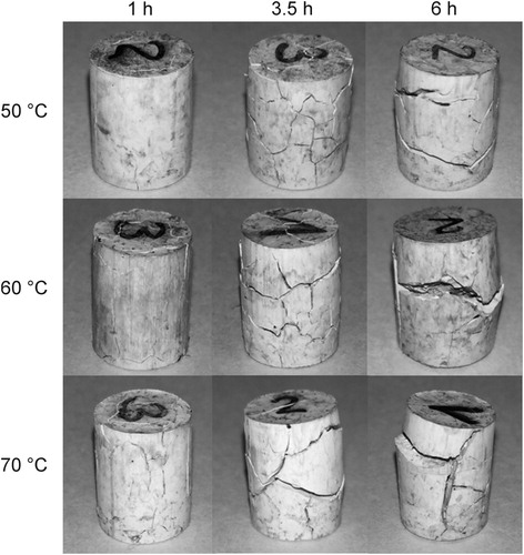
In (a) the loss of soluble binder at different times and temperatures can be observed. The increase in temperature clearly increases the debinding rate. An increase in temperature not only produces an increase in the solubility of the binder, but also facilitates the diffusion of the solvent into the specimen and of the dissolved polymers out to the components [Citation22]. Nevertheless, these results must be evaluated together with the dimensional variation and defects observed in the parts, since these values are also expected to increase with the temperature increase [Citation13].
Figure 5. (a) Loss of soluble binder and (b) length change over time at different temperatures for feedstock A.
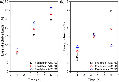
The maximum length change values at the different evaluated conditions are plotted in (b). A larger dimensional variation occurs when debinding at a higher temperature at 1 h, but the opposite trend occurs after 6 h. According to previous studies, a peak of swelling is observed due to the expansion of the soluble components prior to their diffusion out of the specimen [Citation13,Citation23]. Observing , it can be stated that the swelling peak is observed at 3.5 h for 70°C, not being observed for the other temperatures and times. In addition, the highest swelling value at 6 h is obtained at 50°C, since a smaller amount of binder could be leached compared to the other temperatures. The improvement of the diffusion rate of the dissolved TPE seems to reduce the dimensional variation.
Incorporation of SA into binder formulation
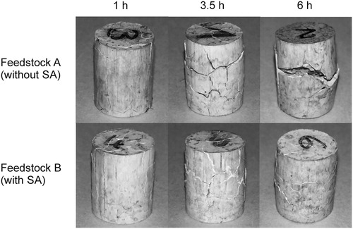
In , the defects observed in the feedstocks without (Feedstock A) and with SA (Feedstock B) at different times and at 60°C can be observed. The incorporation of SA into the binder formulation resulted in a reduction of the cracks size, especially at longer debinding times. Nevertheless, it did not solve the appearance of cracks. In order to quantify the effect of the stearic acid incorporation, the loss of soluble binder and the length change were determined for both feedstocks.
Figure 6. Defects observed in solvent debound specimens for feedstocks without (feedstock A) and with SA (feedstock B).
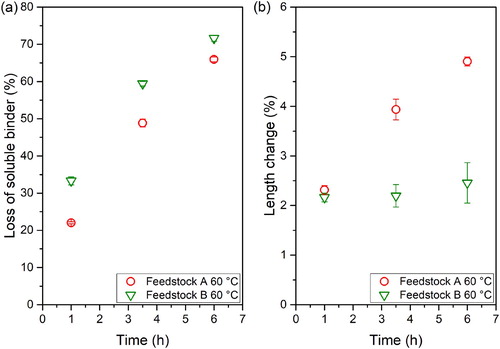
(a) shows the loss of soluble binder for the tested feedstocks at different times and at 60°C. The fraction of removed binder after the incorporation of SA increases at all measured times. Two phenomena might explain this improvement. First, the stearic acid has a lower molecular weight and a lower melting temperature than the thermoplastic elastomer in the binder, thus enhancing the dissolution and mobility of the dissolved polymer [Citation24,Citation25]. Additionally, the dissolution process might be facilitated by the improvement in the dispersion of the powder, which has been reported for ceramic oxide feedstocks containing SA [Citation26]. The length change of specimens was compared to determine the influence of the surfactant in the dimensional variation. It was observed that the use of SA clearly reduces the length of samples after immersion in cyclohexane ((b)), which results in smaller defects (). The small molecular weight of SA not only improves the mobility and dissolution, but results also in less swelling [Citation24,Citation25]. Additionally, the improvement of the powder dispersion in the specimens contributes to a further reduction in defects, since the reduced swelling caused by the solvent penetration into the specimen is also homogeneous in the part.
Figure 7. (a) Loss of soluble binder and (b) length change over time at 60°C for feedstocks without (feedstock A) and with SA (feedstock B).
Incorporation of isopropanol as swelling inhibitor
shows specimens after the immersion at different times in cyclohexane without and with 10 vol.-% of isopropanol. No significant changes in the cracks could be observed at any of the immersion times evaluated. Therefore, the use of isopropanol as inhibitor could not be considered as an effective solution for the large defects observed in the tested system.
Figure 8. Defects observed in solvent debound specimens after debinding in different solvents at 1, 3.5 and 6 h.
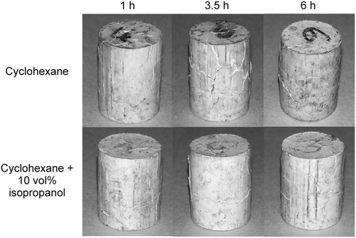
In (a), the loss of soluble binder () over time for the different solvents is plotted. Only a small binder fraction (around 10% of binder) could be leached out of the specimens with isopropanol. For the tests combining cyclohexane with 10 vol.-% of isopropanol no significant changes were observed compared to those using only cyclohexane as solvent. The high concentration of solvent per mass of part and the partial solubility of some of the components of the thermoplastic elastomer in isopropanol might explain why no difference was observed.
Figure 9. (a) Mass loss of soluble binder and (b) length change over time in different solvents.
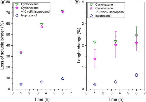
A different trend was observed by Fan et al. [Citation19] for paraffin wax Powder Injection Moulding (PIM) feedstocks, where a clear reduction in the dissolved fraction was measured when incorporating the swelling inhibitors. The feedstock used in our investigation contains a commercial TPE as soluble component; commercial TPEs are multicomponent compounds. As it can be observed in , 10% of the TPE is soluble in isopropanol, which might be enough to compensate for the replacement of 10 vol.-% of cyclohexane. (b) shows the change in length with time for different solvents at a temperature of 60°C. For pure isopropanol, a small length change was measured. The immersion of the specimen into a polar solvent results in a small dimensional variation due to the poor interaction with the binder as observed in the mass loss values. Incorporating 10 vol.-% of isopropanol only reduced the length change at short times. For the rest of the tested times, the incorporation of the second solvent did not have a significant effect reducing swelling and cracks still developed in all the specimens tested (). The partial solubility of the binder in isopropanol can be the reason of the ineffectiveness of this substance as swelling inhibitor. Fan et al. [Citation19] showed that alcohols could be used as swelling inhibitors, while using substances that are able to partially dissolve the binder had no significant effect reducing swelling. In addition, paraffin wax employed by Fan et al.[Citation19] has a smaller molecular weight than TPE and thus less swelling is expected. This might explain the discrepancies observed here.
Conclusions and outlook
A new binder system has been developed, which allows processing of highly filled filaments by FFF with metal and ceramic particles that later on can be solvent debound and sintered for the production of metal and ceramic parts. Unlike its metallic counterparts, feedstocks containing zirconia experience crack formation during solvent debinding [Citation11]; this has been attributed to the smaller particle size and the use of a binder with a large swelling. Despite the debinding rate could be increased at high temperatures, the large cracks observed in the specimens occurred at all temperatures investigated. The incorporation of SA to the binder in the melt mixing process could improve the debinding rate and contribute to the reduction of defects, but it did not completely eliminate cracks. Incorporating isopropanol as a swelling inhibitor has been also studied here, observing no significant changes in the debinding rate and defects.
For further reduction of the dimensional variation and defects, the modification of other parameters will be studied in further steps. For instance, the improvement of the particle dispersion by using compounding equipment with an increased shear and dispersive mixing, such as co-rotating twin screw extruders and the modification of the binder formulation to reduce swelling and increase the debinding rate.
Disclosure statement
No potential conflict of interest was reported by the authors.
Notes on contributors
Christian Kukla is an expert in polymer engineering and the polymer-related processes in powder metallurgy MIM and Additive Manufacturing-AM/Material Extrusion. He is working in the field of MIM since 1995 and in the field of AM since 2012. His current position is at the Industrial Liaison Department of the Montanuniversitaet Leoben, where he is responsible for R&D projects together with the industry.
Santiago Cano received the M. Sc. degree in Industrial Engineering from the University of Castilla-La Mancha in 2016. After the completion of his studies, he started working at the Institute of Polymer Processing of the Montanuniversitaet Leoben, where he is currently pursuing his PhD degree. His research interests include the production of ceramics and metals by powder injection moulding and fused filament fabrication, with focus on the development of binder formulations.
Dario Kaylani received the B.Sc. degree in Polymer Engineering and Science from theMontanuniversitaet Leoben in 2017. Currently he is pursuing his M.Sc. degree at the Institute of Polymer Processing of the Montanuniversitaet Leoben. His research interests are the processing and characterization of polymer composites, including feedstocks for powder injection moulding.
Stephan Schuschnigg received his M.Sc. Degree in polymer engineering at the Montanuniversitaet Leoben. His PhD deals with the solid conveying zone of single screw extruders. Currently he is the work group leader for Additive Manufacturing and Extrusion at the Institute of Polymer Processing in the Department of Polymer Engineering and Science. His main research is material extrusion and the use of highly filled systems.
Prof. Clemens Holzer received his PhD in Polymer Engineering and Science at Montanuniversitaet Leoben. After seven years in the industry at Huber+Suhner, Switzerland as research engineer, head of production and finally head of research and development in a business unit he was deputy head of the Institute of Polymer Nanotechnology INKA and associate professor at FHNW, Switzerland. Since 2009 head of Polymer Processing at the Department of Polymer Engineering and Science and full professor at Montanuniversitaet Leoben. His main research themes are injection moulding, extrusion, compounding, recycling, additive manufacturing, simulation and determination of material data.
Joamin Gonzalez-Gutierrez received the PhD degree in Mechanical Engineering from the University of Ljubljana, Slovenia in 2014. Currently he is a postdoctoral researcher at the Institute of Polymer Processing, Montauniversitaet Leoben, Austria. His research interest includes powder injection moulding, additive manufacturing, and development and characterisation of highly filled polymeric systems.
ORCID
Christian Kukla http://orcid.org/0000-0002-2233-009X
Santiago Cano http://orcid.org/0000-0001-6361-6185
Stephan Schuschnigg http://orcid.org/0000-0002-2601-967X
Clemens Holzer http://orcid.org/0000-0001-5149-7895
Joamin Gonzalez-Gutierrez http://orcid.org/0000-0003-4737-9823
Additional information
Funding
References
- Boschetto A, Bottini L, Veniali F. Finishing of fused deposition modeling parts by CNC machining. Robot Comput Integr Manuf. 2016;41:92–101. DOI:10.1016/j.rcim.2016.03.004.
- Spoerk M, Gonzalez-Gutierrez J, Sapkota J, et al. Effect of the printing bed temperature on the adhesion of parts produced by fused filament fabrication. Plast, Rubber Compos. 2018;47(1):17–24. DOI:10.1080/14658011.2017.1399531.
- Gonzalez-Gutierrez J, Cano S, Schuschnigg S, et al. Additive manufacturing of metallic and ceramic components by the material extrusion of highly-filled polymers: A review and future perspectives. Materials (Basel). 2018;11(5), DOI:10.3390/ma11050840.
- Wu G, Langrana NA, Rangarajan S, et al. Fabrication of metal components using FDMet: fused deposition of metals. Solid Freeform Fabrication Symposium; 9–11 August; Austin, Texas, 775–782.
- Cruz N, Santos L, Vasco J, et al. Binder system for fused deposition of metals. Euro PM2013 Congress & Exhibition; 15–18 September; Gothenburg, Sweden. EPMA, 79–84.
- Agarwala MK, Jamalabad VR, Langrana NA, et al. Danforth: ‘structural quality of parts processed by fused deposition’. Rapid Prototyp J. 1996;2(4):4–19. DOI:10.1108/13552549610732034.
- McNulty TF, Mohammadi F, Bandyopadhyay A, et al. Development of a binder formulation for fused deposition of ceramics. Rapid Prototyp J. 1998;4(4):144–150. DOI:10.1108/13552549810239012.
- Pistor CM. Thermal properties of green parts for fused deposition of ceramics (FDC). Adv Eng Mater 2001;3(6):418–423. DOI:10.1002/1527-2648(200106)3:6<418::AID-ADEM418>3.0.CO;2-Q.
- Agarwala MK, van Weeren R, Bandyopadhyay A, et al. Filament feed materials for fused deposition processing of ceramics and metals’. solid Freeform fabrication Symposium. Austin (TX): University of Texas.
- Gonzalez-Gutierrez J, Godec D, Kukla C, et al. Shaping, debinding and sintering of steel components via fused filament fabrication. 16th International Scientific Conference on Production Engineering; 8 –10 June; Zadar, Croatia. Croatian Association of Production Engineering, 99–104.
- Kukla C, Gonzalez-Gutierrez J, Cano S, et al. Fused filament fabrication (FFF) of PIM feedstocks. VI Congreso Nacional de Pulvimetalurgia y I Congreso Iberoamericano de Pulvimetalurgia; Ciudad Real, Castilla La Mancha, Spain. Comité Español de Pulvimetalurgia, 1–6.
- Gonzalez-Gutierrez J, Duretek I, Holzer C, et al. Filler content and properties of highly filled filaments for fused filament fabrication of magnets. ANTEC, Anaheim, CA, USA, 8–10 May. Society of Plastics Engineers, 1–4.
- Westcot EJ, Binet Andrandall C, German RM. In situ dimensional change, mass loss and mechanisms for solvent debinding of powder injection moulded components. Powder Metall. 2003;46(1):61–67. DOI:10.1179/003258903225010442.
- Contreras JM, Jiménez-Morales A, Torralba JM. Fabrication of bronze components by metal injection moulding using powders with different particle characteristics. J Mater Process Technol. 2009;209(15–16):5618–5625. DOI:10.1016/j.jmatprotec.2009.05.021.
- Mutsuddy BC, Ford RG. Ceramic injection moulding. London: Chapman & Hall; 1995.
- Hwang K-S, Lin HK, Lee SC. Thermal, solvent, and vacuum debinding mechanisms of PIM Compacts. Mater Manuf Processes. 1997;12(4):593–608. DOI:10.1080/10426919708935169.
- Liu W, Xie Z, Yang X, et al. Surface modification mechanism of stearic acid to zirconia powders induced by ball milling for water-based injection molding. J Am Ceram Soc. 2011;94(5):1327–1330. DOI:10.1111/j.1551-2916.2011.04475.x.
- Brydson JA. Plastics materials. 7th edn. Boston (MA): Butterworth-Heinemann; 1999.
- Fan YL, Hwang K-S, Su SC. Improvement of the dimensional stability of powder injection molded compacts by adding swelling inhibitor into the debinding solvent. Metall and Mat Trans A. 2008;39(2):395–401. DOI:10.1007/s11661-007-9351-y.
- Lin ST, German, RM. Extraction debinding of injection molded parts by condensed solvent. Int J Powder Metall. 1989;21(5):19–24.
- Lin H-K, Hwang K-S. In situ dimensional changes of powder injection-molded compacts during solvent debinding. Acta Mater. 1998;46(12):4303–4309. DOI:10.1016/S1359-6454(98)00093-7.
- Tsai D-S, Chen W-W. Solvent debinding kinetics of alumina green bodies by powder injection molding. Ceram Int. 1995;21(4):257–264. DOI:10.1016/0272-8842(95)99791-9.
- Hu SC, Hwang K-S. Length change and deformation of powder injection-molded compacts during solvent debinding. Metall and Mat Trans A. 2000;31(5):1473–1478. DOI:10.1007/s11661-000-0265-1.
- Park MS, Kim JK, Ahn S, et al. Water-soluble binder of cellulose acetate butyrate/poly(ethylene glycol) blend for powder injection molding. J Mater Sci. 2001;36:5531–5536. doi: 10.1023/A:1012579010171
- Hayat MD, Wen G, Zulkifli MF, et al. Effect of PEG molecular weight on rheological properties of Ti-MIM feedstocks and water debinding behaviour. Powder Technol. 2015;270:296–301. DOI:10.1016/j.powtec.2014.10.035.
- Lin ST, German RM. Interaction between binder and powder in injection moulding of alumina. J Mater Sci. 1994;29(19):5207–5212. DOI:10.1007/BF01151118.