
 ?Mathematical formulae have been encoded as MathML and are displayed in this HTML version using MathJax in order to improve their display. Uncheck the box to turn MathJax off. This feature requires Javascript. Click on a formula to zoom.
ABSTRACT
In modern AC technologies, improving the power efficiency of soft magnetic core materials is a key factor. Powder metallurgy offers a promising alternative for these applications: Soft Magnetic Composites are compacted iron-based powders, each iron particle being electrically insulated from its neighbours by a superficial layer. Accordingly, the thermal stability of the insulating layers used plays an essential role, because the stresses and defects introduced by pressing must be relieved by heat treatment. The thermal stability of FePO4, which is a common insulating barrier, is limited. In the present study, the degrading mechanism was investigated using a mixture of high purity iron powder and FePO4·2H2O. The samples were characterised using a wide variety of analytical methods (DTA/TG, ATR-IR, XRD and XPS). The results show that a ferrothermal reduction takes place, the base material of SMCs – metallic Fe – acting as a reducing agent.
1. Introduction
Soft magnetic powder metallurgical materials (e.g. Fe–P, Fe–Si, Fe–Ni, Fe–Co) are well known, especially for the applications in DC and low frequency AC ranges [Citation1–5]. In the applications for higher frequencies (AC motors, transformers, generators, etc.), high resistivity plays an important role due to the increasing relevance of eddy current losses. Therefore, in such applications traditional powder metallurgical materials cannot compete with commercially available ferrites – which are non-conductive – or with laminated steel sheets which significantly reduce the radii of the eddy currents due to the layered structure [Citation6–8]. However, powder metallurgy also offers a promising alternative for higher frequencies: the so-called soft magnetic composites (SMCs) are compacted iron-based powders, each Fe-particle in this compact being electrically separated from its neighbour by an insulating surface layer (see ). SMCs have raised much interest in the late 1990s and early 2000s [Citation9–22]; with the trend to electrification in automotive transport, renewed research activities are being recorded in recent years.
Figure 1. Structure of SMC particles [Citation23].
![Figure 1. Structure of SMC particles [Citation23].](/cms/asset/7e3674f9-3c81-4b9c-9ab3-276b22f01841/ypom_a_1909211_f0001_oc.jpg)
Since SMC components are manufactured using the powder metallurgical route, there is a very broad spectrum of relevant process parameters, which enables accordingly a wide range of properties to be covered. It is precisely this fact that makes the development of new types of SMC materials so attractive. In general, the processing route of SMC powders can be classified into three areas: (1) powder selection, (2) pressing, (3) heat treatment [Citation9,Citation12,Citation13]. Above all, the recovery annealing of the SMC is an essential process, since the stresses and defects introduced into the ferrous lattice by the pressing must be relieved to reduce the hysteresis losses. However, excessive damage to the insulating layer, which microstructural feature is the key factor in this technology to reduce the eddy current radii, must be prevented.
The use of FePO4 layers has been practised for a long time, and this is one of the most popular powder coating variants due to the excellent insulation properties and simple coating process [Citation12,Citation13]. However, the limited thermal stability of FePO4, especially at temperatures around 600°C, is well known [Citation24,Citation25]. Thus, when using FePO4 layers, a complete recovery of the crystal lattice with a simultaneous maximum effectiveness of the insulating layer cannot be achieved, and a compromise between minimising the hysteresis losses and the eddy current losses, respectively, is required. Therefore, the mechanisms that lead to the thermal degradation of FePO4 at this temperature range are of supreme interest and will be investigated in this work.
2. Theory
The main characteristic of soft magnetic core materials for AC applications, such as soft magnetic composites, is the so-called core loss [Citation9,Citation12–14]. The core loss corresponds to the heat output that is generated when a ferromagnetic core material is polarised back and forth at a given frequency and magnetic flux density. The amount of heat generated must be minimised for optimal performance efficiency of the corresponding units. Mathematically, the core loss is represented by the following equation (neglecting the anormal loss PA due to its low technical importance in SMCs) [Citation26]:
where Pc, PH and PEC correspond to the core, hysteresis, and eddy current losses in W m–³ and W kg–1. CH and CEC are flux density-dependent material parameters (hysteresis and eddy current parameters). In addition, f describes the magnetisation frequency. The equation shows that the eddy current losses increase with the frequency as a square function, while the hysteresis losses have a linear dependence, whereby the eddy current losses are becoming increasingly important in the higher frequency range. Since the thermal stability of FePO4 in phosphatised SMCs is strongly limited, especially at temperatures above 600°C, annealing the SMCs at those temperatures leads to lower PH but on the other hand to an accelerated increase of CEC and thus eddy current loss PEC. Moreover, in high frequency applications the above-mentioned degradation of the insulating layer has a particularly negative effect regarding the square dependence of the eddy current losses on the frequency. Nevertheless, as stated above, FePO4 is a popular insulating layer in SMCs [Citation12,Citation13,Citation25], so the underlying mechanism that leads to thermal degradation is highly relevant in industrial application.
3. Experimental details
In order to generate signals with a sufficiently high intensity, the degradation of FePO4 in contact with Fe was not carried out using original phosphatised SMC powders – the overall phosphate content being very low there – but instead a commercial pure iron powder grade – ABC 100.30 from Höganäs AB, Sweden – was mixed with fine powdered FePO4·2H2O from Sigma-Aldrich, Germany, in a tumbling mixer with steel balls and spiral for 10 min. This mixture should simulate the structure of phosphatised SMC powders (metallic Fe + FePO4, e.g. the Somaloy types from Höganäs, Sweden). In addition, pure FePO4·2H2O was used in the following investigations as a reference to differentiate between decomposition reactions of the plain phosphate and those reactions occurring in the Fe–FePO4·2H2O mixture through interaction between Fe and FePO4. First, DTA/TG measurements were carried out in Ar atmosphere (purity: 99.999%) within a temperature range of 25–1000°C and with a heating and cooling rate of 20 K min–1 using a Netzsch STA449C (Jupiter) device. The DTA/TG graphs obtained were evaluated using the Proteus Thermal Analysis software from Netzsch, Germany, the respective signals being compared with an empty crucible.
In parallel, powder samples were annealed in an electrically heated pusher furnace with Kanthal heating elements and a gas-tight heat-resistant steel muffle (1.4841) using the push-in-push-out method and applying annealing temperatures between 400°C and 800°C. Annealing time was set for 20 min in N2-atmosphere (purity: 99,999%, gas flow: 2 L min–1). N2 was used here since it is the most common inert atmosphere in ferrous powder metallurgy.
The annealed samples were subsequently characterised using Attenuated Total Reflection Infrared Spectrometry (ATR-IR), X-ray diffraction (XRD) and X-ray photoelectron spectrometry (XPS). An FT-IR Spectrometer ‘Spectrum 65’ from PerkinElmer, USA, was used for the ATR-IR measurements. The X-ray diffractograms were recorded on a standard Bragg–Brentano diffractometer in vertical θ–θ geometry (PANalyical XPert) with a line detector using Cu Kα radiation. The fluorescence which occurs in the presence of iron did not negatively affect the evaluation of the diffractograms. The samples were put on a Si single crystal carrier with the {711} plane on the surface, and a sample area of 4 × 10 mm² was illuminated during the measurements. The measuring range recorded by the detector was 5–120° 2θ. A Ni-filter was used to eliminate parts of the Cu Kβ radiation. The ‘HighScore’ program from PANalytical was used to evaluate the X-ray diffraction patterns.
The XPS measurements were carried out on a SPECS XPS spectrometer with Al Kα radiation and a hemispherical WAL-150 analyser (µFocus 350). The powder samples used for the measurement were first placed on Indium foils and pushed through a three-stage lock system into the measuring chamber, where a pressure of 1 × 10⁻⁹ mbar was set. During the measurements, a beam power of 70 W was used, whereby an area of 400 × 400 µm² was illuminated. Monochromatising the emitted X-rays took place via specially heated Si plates which exactly fulfilled the Bragg conditions for the characteristic Al Kα radiation (1486.6 eV). The emitted electrons were recorded using a Concentric Hemispherical Analyzer (CHA). To improve the signal–noise ratio, five measurements were carried out at different angles (27°, 39°, 51°, 63°, 75°) from the sample table to the entrance slit of the CHA, with 10 individual measurements being recorded at each of these angles. The recorded spectra were evaluated using the CASA XPS software. The signals were calibrated by correcting the C1s signal to a value for the binding energy of 284.8 eV.
4. Results
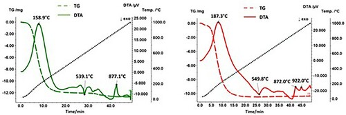
shows the DTA/TG results both for the mixture Fe + FePO4·2H2O and for the pure compound FePO4·2H2O. Thus, the DTA/TG measurements clearly show that an interaction between metallic Fe and FePO4·2H2O occurs during the heat treatment. While the course of the DTA curve has stabilised at approx. 380°C (outgassing of H2O) when measuring pure FePO4·2H2O after the end of the dehydration reaction, the curve of Fe + FePO4·2H2O drifts into the exothermic range, and a peak was detected at approx. 550°C. The characteristic signals observed with the Fe + FePO4·2H2O sample at 760°C and 930°C can be assigned to the Curie temperature and to the ferrite-austenite transformation, respectively.
Figure 2. DTA/TG curves of FePO4·2H2O (left) and Fe + FePO4·2H2O (right) at a heating and cooling rate of 20 K min–1 in Ar. Solid line: DTA; broken line: TG.
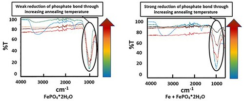
In parallel the powder samples were annealed in the pusher furnace at different temperatures. shows that the colour development of the different powder samples is fundamentally different. While the colour of the pure FePO4·2H2O changes from light yellow to brown, in Fe + FePO4·2H2O a black powder is formed. The ATR-IR spectra in show that the presence of the Fe powder lowered the intensity of the phosphate band located at 1100 cm−1, the more the higher the temperature was. The decreasing intensity of the phosphate band is caused by the thermally induced degradation of the phosphate, which has already been proven in earlier work in phosphatised SMCs [Citation24,Citation25]. To enable a detailed consideration, which describes the responsible mechanism leading to the degradation of FePO4, the samples annealed at 600°C and 800°C were further characterised using XRD und XPS. Especially the results for of 600°C are of high interest because it is well known that this temperature is a critical threshold for the stability of FePO4 in SMCs. Furthermore, the investigations at 800°C were also examined to assess whether a change in the present mechanism occurs when the temperature is increased.
Figure 3. Colour of the annealed samples caused by annealing at different temperatures in inert atmosphere.
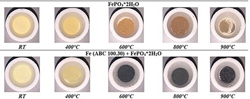
Figure 4. Evolution of the phosphate bands in the ATR-IR spectra caused by annealing at different temperatures in inert atmosphere.
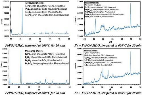
The XR diffraction patterns of both systems differ fundamentally. While in pure FePO4·2H2O the formation of Fe2O3 and P2O5 was detected, the X-ray diffraction patterns of the Fe + FePO4·2H2O sample primarily show the formation of Fe3(PO4)2, indicating a reduction of the Fe in the phosphate from oxidation state 3+ to 2+. In addition, the formation of intermediate phosphates (mean oxidation state of Fe: 2–3+) was also detected in the Fe-containing sample (the peak at 45° indicates bcc Fe). By recording the XPS spectra, the characteristic binding energies of the emitted electrons enabled the chemical surroundings of the elements to be determined. Thus, the corresponding compounds were identified. While in the iron-phosphate mix P is only present in the form of phosphate in the initial state, the formation of P2O5 at 600°C (P2p: binding energy: 135.5 eV) and the formation of Fe3P at 800°C (P2p: binding energy: 128.7 eV) were detected ( and ).
Figure 5. XPS measurements after heat treatment at 600°C and 800°C in high purity N2.
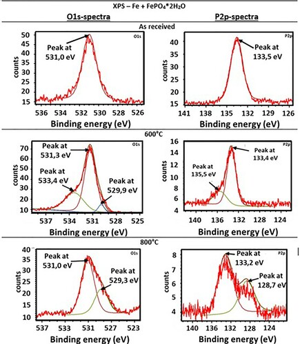
Table 1 . Binding energies of the detected P2p and O1s states of the Fe + FePO4·2H2O samples, including comparison with database values [Citation27,Citation28].
5. Discussion
The results above (DTA/TG, colour development of the powder, ATR-IR) have already shown that the presence of Fe has a decisive influence on the stability of iron phosphate at elevated temperatures. The ATR-IR studies proved that metallic Fe, as it is also present in SMCs as substrate, accelerates the thermal degradation of FePO4. In the following explanations, the proposed reaction mechanisms during the heat treatment of the powder samples are discussed.
5.1. FePO4·2H2O
The XRD measurements in indicate that annealing of the pure phosphate FePO4·2H2O at 600°C and 800°C resulted in formation of P2O5 and Fe2O3. The following decomposition reaction is the most likely option:
(1)
(1) whereby the formation of Fe3PO7 according to the following reaction was proven by the XRD measurements:
(2)
(2)
Figure 6. XRD and XPS measurements after heat treatment at 600°C and 800°C in high purity N2.
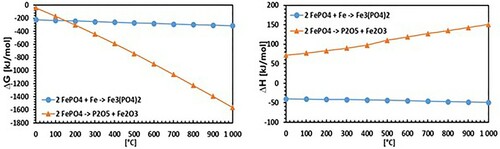
Through thermodynamic simulations using HSC chemistry software () it was also checked if the assumed reaction (1) can theoretically take place. This evaluation can be assessed as affirmative regarding the negative Gibbs free energy.
Figure 7. Calculation of ΔG (left) and ΔH (right) through thermodynamic simulations using HSC chemistry 4.0 software.
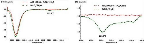
Accordingly, the heat treatment of pure FePO4 results in the formation of P2O5, which has a relatively high vapour pressure at the annealing temperatures used. In this regard, a corresponding signal could also be detected in the TG measurements (), with a mass loss occurring from a temperature of approx. 710°C, which can be attributed to the evaporation of the volatile P2O5. The fact that the registered signal is rather weak also agrees well with the ATR-IR spectra of plain FePO4·2H2O which indicate that reaction (1) is only implemented very slowly. In addition, shows that in the case of the Fe + FePO4·2H2O mixture, no such mass loss signal was detected that would indicate the removal of P2O5, although the formation of this compound was detected at annealing temperatures of 600°C. Possible causes are described in 5.2.
Figure 8. DTG (left and enlarged section right) results on the FePO4·2H2O and Fe + FePO4·2H2O samples, heating/cooling rate: 20 K min–1.
5.2. Fe + FePO4·2H2O
In contrast to the pure FePO4·2H2O, fundamentally different results were obtained in the mixture of Fe and FePO4·2H2O. First, with increasing annealing temperatures, a progressively lower intensity of the phosphate band was detected, which was also often observed in phosphatised SMCs. This relationship is due to the thermal degradation of the phosphate, which obviously is strongly accelerated by the presence of metallic Fe (see ; comparison between FePO4·2H2O and Fe + FePO4·2H2O). In previous works it was shown that especially temperatures ≥600°C are detrimental for the stability of the phosphate. In these temperature ranges the X-ray diffractograms in indicate that a ferrothermal reduction of the FePO4 takes place, with a progressive reduction of the mean oxidation state of iron. The participation of metallic Fe in the cited reaction is evident because the heat treatment of pure FePO4·2H2O did not lead to the formation of Fe2+. In addition, a reducing agent is essential here, with no other option than metallic Fe being present.
(3)
(3) The single reactions above could not be simulated by the thermodynamic database-software HSC chemistry, because the ‘intermediate’ phosphates have no entry in the database used. However, the formation of these compounds is clearly indicated by XRD. In addition, total reaction (3) is possible in principle due to the negative free Gibbs energy obtained by the thermodynamic simulations. The listed reactions show that in fact a ferrothermal reduction of FePO4 occurs, whereby the base material of SMCs – metallic Fe – acts as a reducing agent. The ATR-IR spectra show that the formation of Fe3(PO4)2 is an intermediate state, as the mechanism mentioned does not include the degradation of the phosphate band observed in the ATR-IR spectra. Correspondingly, a subsequent reaction leads to the degradation of Fe3(PO4)2, with the XPS P2p and O1s spectra in demonstrating the formation of P2O5 at 600°C. In addition, the XPS measurements show that at high heat treatment temperatures (800°C) Fe3P is formed.
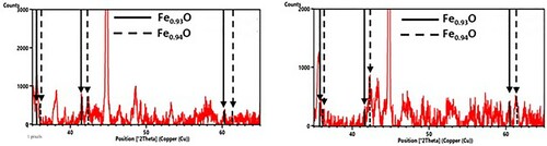
Owing to the oxygen presence, the formation of an O-rich byproduct is essential in these reactions. The XRD measurements in were able to detect the formation of Fe1−xO (wustite), which is plausible due to the Fe2+ which was already formed in the previous reaction (3). The detection of Fe1−xO is clearly indicated through the peaks at 2θ = 60.351 and 61.342°, which could not be assigned to any other phase containing the elements present here. In addition, the O1s spectra of the XPS measurements also indicate the formation of metal oxides such as wustite.
Figure 9. Fe1−x O peaks in diffractograms from ABC 100.30 + FePO4·2H2O samples, 600°C for 20 min (left) and 800°C for 20 min (right).
As already mentioned in 5.1, the DTG did not detect any signal in the Fe + FePO4·2H2O mixture that would indicate the removal of P2O5. First, this could be caused by the thermal instability of P2O5 in the presence of Fe at temperatures >600°C (e.g. formation of Fe3P, see 5.2. proposed reaction at 800°C). Second, the formation of P2O5 could be ‘overrun’ at a heating rate of 20 K min–1, since the formation of P2O5 (in the presence of Fe) is apparently coupled with the formation of Fe1−x.O. As Fe1−xO is known to be thermodynamically stable only at temperatures above 580°C, the higher heating rates used could shift the degradation of Fe3(PO4)2 to the temperature range where Fe3P is already preferentially formed.
Therefore, the following reaction mechanisms are proposed for the thermal degradation of FePO4; the present mechanism is a ferrothermal reduction, whereby metallic Fe acts as a reducing agent.
Table
6. Conclusions
In the present work, the thermal degradation of FePO4 insulating layers, as they occur in phosphatised SMC particles, was investigated. Especially the mechanism presented at 600°C was studied, because earlier works have shown that at this temperature range the breakdown of the FePO4 insulating layer is accelerated. To ensure a sufficient intensity of signals, the structure of such SMC particles was simulated by mixing a pure iron powder (ABC 100.30) with powdered FePO4·2H2O. In addition, all investigations were also carried out on pure FePO4·2H2O as a reference to be able to clearly identify possible interactions between Fe and FePO4. These samples were annealed at different temperatures and characterised using a wide variety of methods (DTA/TG, ATR-IR, XRD, XPS).
The results showed that the presence of metallic Fe leads to accelerated degradation of FePO4. The cause is a ferrothermal reduction, whereby metallic Fe – the basic material of SMCs – acts as a reducing agent. In a first partial reaction FePO4 is reduced by metallic Fe to Fe3(PO4)2. Subsequently, at 600°C the Fe3(PO4)2 formed decomposes to P2O5 and Fe1−xO. It was also found that at 800°C the formed Fe3(PO4)2 decomposes to Fe3P and Fe1−xO (wustite).
Acknowledgement
We acknowledge the financial support and the provision of the powder materials from Miba Sinter Austria GmbH, Vorchdorf, Austria. We would also like to thank the Fachbereich Röntgenzentrum [grant number E057-04] and the Analytical Instrumentation Center [grant number E057-05] of the TU Wien for carrying out the XRD and XPS measurements.
Disclosure statement
No potential conflict of interest was reported by the author(s).
Additional information
Notes on contributors
K. Ouda
K. Ouda studied Technical Chemistry at Technische Universität Wien (Vienna University of Technology), Vienna Austria. Hehas been investigating magnetic components since 2016. From 2017 - 2020 he was project assistant at the Powder Metallurgy Research Group, TU Wien: Institute of Chemical Technologies and Analytics. He received the PhD degree from TU Wien in September 2020.
H. Danninger
H. Danninger is full professor of Chemical Technology of Inorganic Materials at Technische Universität Wien (Vienna University of Technology), Vienna, Austria. From 2011 to 2019 he was also Dean of the Faculty of Technical Chemistry. He has been active in powder metallurgy for more than 40 years and is author/co-author of 500+ publications as well as several books and book chapters. From 2009 to 2020 he was chairman of the“Gemeinschaftsausschuss Pulvermetallurgie”, the PM association of the German-speaking countries. He holds honorary doctoral degrees of Technical University Cluj-Napoca (Romania), Universidad Carlos III de Madrid (Spain) and Universitatea din Craiova (Romania) and is Fellow of APMI and EPMA. In 2020 he was awarded the “Ivor Jenkins Medal” of IOM3.
C. Gierl-Mayer
C. Gierl-Mayer was born in Styria, Austria, in1969. He studied Technical Chemistry at TU Wien, got his Master in 1996 and his PhD in 2000 from TU Wien. After 3 years in private research institute (ofi-Austrian Research Institute of Chemistry and Technology) he re-joined the powder metallurgy group of Prof. Herbert Danninger assenior researcher. He got his habilitation in 2019 for “Thermoanalytical Investigation of Interactions between Powder Metallurgy Steels and the Atmosphere during Sintering”, and became Associate Professor in 2019. He is currently leading the research group Powder Metallurgy at TU Wien, Institute of Chemical Technologies and Analytics. His publication record is about 260 publications in journals and conference proceedings, 4 book chapters and 7 patents.
R. Hellein
R. Hellein Studied Technical Chemistry at Vienna University of Technology with PhD in the field of “Co-sintering ofcemented carbides” (Institute of Chemical Technologies and Analytics). 2016 he joined Miba Sinter Austria GmbH as R&D Engineer Materials & Processing Technology. From 2018 he has been Team leader for Material Development, R&D Sinter Group.
A. Müller
A. Müller He studied MechanicalEngineering and Economics at Vienna University of Technology with a PhD thesis in the field of RFID Technology. In 2006 he started at Miba SinterAustria GmbH as Development engineer; from 2008 he was teamleader in the area of R&D. In 2013 he became Manager R&D: AdvancedEngineering, and since 2016 he has been Head of R&D Miba Sinter Group.
References
- Dougan, MJ. High Performance sintered soft magnetic materials. Proceedings of the PM World Congress PM2010; 2010; Florence, Italy. Shrewsbury UK: EPMA; vol. 5. p. 229–236.
- Moyer KH, McDermott MJ, Topolski MJ, et al. Magnetic properties of iron alloys. Powder Technol. 1981;30:51–71.
- Moyer KH, Ryan JB. Enhanced properties of emerging powders for magnetic components. Met Powder Rep. 1990;45:202–207.
- Dougan MJ. Powder metallurgical materials and processes for soft magnetic applications. Workshop on SRM drives an alternative for E-traction, Barcelona, Spain [cited 2020 Aug 9]. Available from: webside:upcommons.upc.edu/bitstream/handle/2117/116155/01_powder_metallurgical_materials_processes_soft_magnetic_applications.pdf?sequence=1&isAllowed = y.
- Capus JM. PM soft magnets in new applications. Met Powder Rep. 2002;57:20–21.
- Cheng Z, Takahashi N, Forghani B, et al. Analysis and measurements of iron loss and flux inside silicon steel laminations. IEEE Trans Magn. 2009;45:1222–1225.
- Atallah K, Howe D. Calculation of the rotational power loss in electrical steel laminations from measured H and B. IEEE Trans Magn. 1993;29:3547–3549.
- Brauer JR, Cendes ZJ, Beihoff BC, et al. Laminated steel eddy current loss versus frequency computed using finite elements. IEEE Trans Magn. 2000;36:1132–1137.
- Janghorban K, Shokrollahi H. Soft magnetic composite materials (SMCs). J Mater Process Technol. 2007;189:1–12.
- Janghorban K, Shokrollahi H. Effect of warm compaction on the magnetic and electrical properties of Fe-based soft magnetic composites. J Magn Magn Mater. 2007;313:182–186.
- Janghorban K, Shokrollahi H. Different annealing treatments for improvement of magnetic and electrical properties of soft magnetic composites. J Mag Mater. 2006;317:61–67.
- Oikonomou C. On surface characteristics and microstructural development of soft magnetic composite powder and components [doctoral thesis]. Gothenburg (Sweden): Chalmers University of Technology; 2015.
- Oikonomou C. Surface characterization of soft magnetic composite powder and compacts [master thesis]. Gothenburg (Sweden): Chalmers University of Technology; 2014.
- Taghvaei AH, Shokrollahi H, Janghorban K, et al. Eddy current and total power loss separation in the iron-phosphate-polyepoxy soft magnetic composites. Proceedings of the Euro PM2000 Conference Soft Magnetic Materials Workshop; 2000; Munich, Germany. Shrewsbury, UK: EPMA; p. 9–14.
- Krögen Ö, Jack AG. Insulated iron powder (SMC) used as Soft Magnetic Material in a rotating electrical machine. In: Kosuge K, Nagai H, editors. Proceedings of the PM World Congress PM2000; 2000; Kyoto, Japan: Tokyo: JPMA; p. 1368–1371.
- Hemmati I, Hosseini HRM, Miraghaei S. Effect of processing parameters on electrical, mechanical and magnetic properties of iron-resin soft magnetic composite. Powder Metall. 2007;50:86–90.
- Pelletier S, Lefebvre LP, Thomas Y. Influence of grain size on the properties of soft magnetic iron-resin composites. Proceedings of the PM World Congress PM98 Granada; 1998; Spain. Shrewsbury, UK: EPMA; Vol. 5, p. 514–519.
- Bas JA, Morató J, Calero JA, et al. Applications for encapsulated powder materials in electric motors. Proceedings of PM2000 World Congress Soft Magnetic Material Workshop; 2000 Munich, Germany. Shrewsbury, UK: EPMA; p. 1344–1347.
- Krögen Ö, Granberg P. Soft magnetic composites: materials with tuneable magnetic properties. Proceedings of PM2000 Congress Soft Magnetic Material Workshop; 2000; Munich, Germany. Shrewsbury, UK: EPMA; p. 1352–1355.
- Rodrigues D, Emura M, Landgraf FJG, et al. Insulated iron powders: process and magnetic properties. Proceedings of the Euro PM2000 Congress Magnetic Material Workshop; 2000; Munich, Germany. Shrewsbury, UK: EPMA; p. 1360–1363.
- Hamill JA, Narasimhan S, Miller DJ. Soft magnetic iron composite – new application developments. Proceedings of the Euro PM2001 Congress Magnetic Material Workshop; 2001; Nice, France. Shrewsbury, UK: EPMA; Vol. 2, p. 257–261.
- Jansson P. Soft magnetic composites – a rapidly expanding materials group. Adv Powder Metall Part Mater. 1998;3:3–9.
- Nikas D. Characterization of electrically insulating coatings for soft magnetic composite materials by means of surface sensitive analytical techniques [master thesis]. Gothenburg (Sweden): Chalmers University of Technology; 2013.
- Huang M, Wu C, Jiang Y, et al. Evolution of phosphate coatings during high-temperature annealing and its influence on the Fe and FeSiAl soft magnetic composites. J Alloys Compd. 2015;644:124–130.
- Taghvaei AH, Shokrollahi H, Janghorban K, et al. Properties of iron-based soft magnetic composite with iron phosphate–silane insulation coating. J Alloys Compd. 2009;481:681–686.
- Kliman GBN, Lee SBS, Mallic JADS, et al. Methods or apparatus specially adapted for manufacturing, assembling, maintaining or repairing of dynamo-electric machines of stator or rotor bodies. Patent, registration: DE60319885T2; 2008 Apr. 30.
- http://www.xpsfitting.com/ [cited 2018 Jul 15].
- https://xpssimplified.com/. [cited 2018 Jul 15].
- Oikonomou C, de Oro Calderon R, Hryha E, et al. Effect of heat treatment in air on surface composition of iron-phosphate based soft magnetic composite components. Mater Sci Eng B. 2014;189:90–99.