
ABSTRACT
This study reports the variability of the fatigue strength of specimens manufactured by the laser powder bed fusion process with respect to their location on the build plate. Specimens from the right-hand and left-hand halves of the build plate were tested under high cycle fatigue. Comparison of the fatigue data suggests that the specimens manufactured on the right-hand half of the build plate have a higher fatigue strength than those manufactured on the left-hand half. One reason for the observed discrepancy in fatigue strength was the higher accumulation of spattered powder particles on the left-hand side as compared to the right-hand side of the build plate. These spattered particles are oxidised, and form defects such as inclusions within the specimen.
Introduction
Variation of the mechanical properties of parts produced by the laser powder bed fusion (LPBF) process have not yet been thoroughly investigated. A review by Dowling et al. [Citation1] indicates that the key parameters influencing repeatability/reproducibility are: powder properties, laser characteristics, scan pattern, and post processing. The powder properties affect the powder bed density which in turn, influence the thermal conductivity [Citation2] and the optical penetration depth [Citation3–5] of the powder bed. The thermal conductivity and the optical penetration depth of the bed change the melt pool characteristics, which consequently, influence the mechanical properties [Citation6–8]. Abd-Elghany and Bourell [Citation9] conclude that the ultimate tensile strength increases with the increase of the powder bed density. In addition, other factors such as build orientation [Citation10–12], layer thickness [Citation13], process parameters [Citation14], and even the type of LPBF machine can cause variation in the mechanical properties. For example, in LPBF machines where the powder is spread with a raking blade and unidirectionally, the properties of the part vary significantly depending on whether they are located near the start of the recoating stroke or the end [Citation15]. However, in machines in which powder recoating is bidirectional, the spreading direction is not expected to cause variations in mechanical properties. The aim of this study is to investigate the variability of the fatigue strength of parts manufactured by the LPBF process in relation to their location on the build plate.
Materials and methods
The current research is based on gas atomised 316 L stainless steel powder. The material was produced by Höganäs AB (Höganäs, Sweden), and the chemical composition is presented in . According to the material’s specification document the powder had an apparent density of 4.09 g cm–3 and a flowrate (Hall) equal to 16 s/50 g. Gas adsorption analysis based on the BET principle was carried out to measure the specific surface area of the powder particles. For this analysis, a Gemini VII apparatus from Micrometrics (Norcross, Georgia, USA) was used and the powder exhibited a surface area of 0.030 m2 g–1.
Table 1 . Chemical composition (in wt-%) of 316 L stainless steel as stated in the material specification.
Powder particle size was analysed by laser diffraction. The analysis was performed using a Mastersizer 3000 equipment from Malvern (Malvern, UK). The particle size was determined at the 10 (i.e. D10), 50 (i.e. D50) and 90 (i.e. D90) per cent on the cumulative size distribution curve. The equivalent diameter for D10, D50 and D90 was equal to 30.9, 45.4 and 65.9 µm, respectively.
A SLM 125 HL system from SLM Solutions GmbH (Lübeck, Germany) was used to manufacture the fatigue specimens. This machine is equipped with a single 400 W fibre laser and has a build envelope of 125 × 125 × 125 mm3 (reduced by substrate plate thickness). Fatigue specimens were manufactured directly on the build plate and without the use of support structures. The build direction was parallel to the longitudinal axis of the specimens, and the specimens were manufactured with 50 µm lowering steps of the build plate. It should be noted that in the SLM 125 HL system, powder recoating is performed bidirectionally with a rubber lip.
The powder was first, dried at 60°C (for a minimum of 24 h), then sieved, and finally loaded into the LPBF machine. The sieving was carried out in an argon atmosphere with a PSM 100 unit (manufactured by SLM Solutions GmbH) and a 75 μm mesh. During the LPBF processing, argon 4.8 premium gas from Linde (Lidingö, Sweden) was used in order to prevent excessive oxidation. Furthermore, to limit the distortion of the specimens the build plate was kept at 200°C during the entire LPBF process. At the end of the process, the specimens were removed from the build plate using wire electrical discharge machining. The parts were not heat treated.
The specimens were machined to the final dimension. The post machining operation ensured that the effect of surface roughness on fatigue was similar for all specimens. In order to remove machining marks or scratches on the surface, the machining procedure was turning by lathe followed by manual polishing in the longitudinal direction of the specimen. The final geometry of the fatigue specimens was in accordance with ISO 1099.
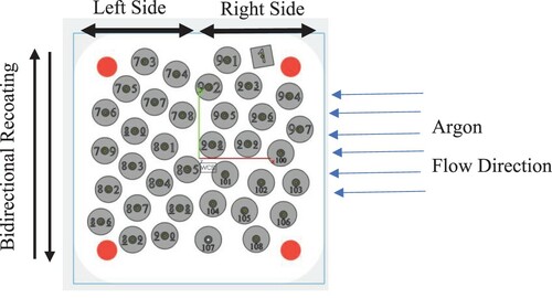
In total, 36 specimens were manufactured on the build plate. The build plate was virtually divided into two halves, and the specimens were divided into two batches: the right-hand side and the left-hand side, see . The fatigue properties of the specimens located on the right-hand side were compared with those placed on the left-hand side. In this study, specimens from the right-hand and the left-hand side were extracted from two identical but subsequent LPBF runs.
Figure 1 . Top view of the layout of the fatigue specimens on the build plate.
In order to see whether there is a correlation between the oxygen content of the specimens and their location on the build plate, two specimens from the utmost right-hand side and two from the utmost left-hand side of the build plate were analysed for oxygen content according to ASTM E1019. The measurement error for this analytical technique is ∼ 0.001 wt-%. In addition, the number of defects within the specimens has been measured with light optical microscopy at 100x magnification and by means of an image analysis software (from Leica Microsystems). For this analysis, two specimens located on the utmost right- and two specimens on the left-hand side of the build plate were selected. From each specimen, in total four cross sections were examined. Two cross sections were extracted from the gage section and parallel to the build direction, and two cross sections were extracted from the top grip head and perpendicular to the build direction.
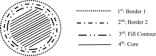
The LPBF process parameters used in this investigation (i.e. 316L_SLM_MBP3.0_50_CE1_400W_Stripes_V1.1) were specifically developed for 316 L stainless steel and were provided by the supplier of the LPBF machine. With this parameter setting the laser spot size was 65 µm, and each layer of the specimens was composed of two borders, one fill contour and the core. First, the two borders were created. Next, the fill contour and, finally, the core of the layer was formed with a stripe laser pattern. The sequence is shown schematically in .
Figure 2. The sequence of the laser path for shaping each layer of a given component.
All fatigue tests were performed with a sinusoidal force function and frequency of 20 Hz at room temperature. The tests were carried out at a stress ratio of R = 0.1, and 2 × 10⁶ cycles were considered as run-out. A minimum of 14 samples for each batch of specimens were tested. A servo-hydraulic material testing machine from MTS (Eden Prairie, Minnesota, USA) was used for the tests. The machine was equipped with hydraulic collet grips and a 100 kN load cell. The fatigue tests were force controlled by means of FlexTest GT controller and MTS MultiPurpose TestWare software. Machine alignment was carried out according to ISO 23788:2012 [Citation16].
Results
The results of the fatigue tests are shown in . The test results suggest a higher fatigue strength for specimens printed on the right-hand side of the build plate as compared to those printed on the left-hand side. For reference, fatigue data for the as-printed condition is also plotted in . The fatigue data for the as-printed specimens is based on a previous investigation which has been performed with the same LPBF system, process parameters and powder [Citation13]. The surface roughness of the as-printed and machined specimens has been reported previously [Citation13]. The arithmetic mean height (i.e. Sa) of the as-printed specimens is 15 µm, while after machining Sa value of 0.5 µm is measured [Citation13]. In addition, the oxygen content of specimens fabricated in different locations on the build plate is shown in .
Figure 3. Fatigue data for 316 L stainless steel material manufactured with 50 µm layer thickness. Data labels show the number of run-outs and the stress amplitude.
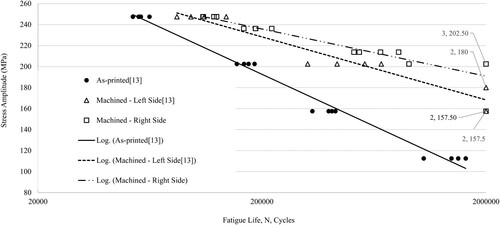
Table 2. Oxygen analysis of specimens from the utmost right- and left-hand side of the build plate.
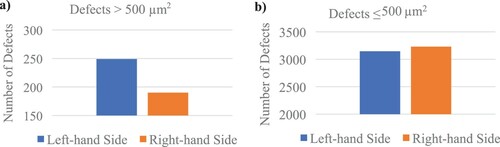
The results of the defect measurements by optical microscopy and image analysis are plotted in . With respect to defects larger than 500 µm2, the measurements show that the specimens manufactured on the left-hand side of the build plate contain a significantly higher number of defects than those on the right-hand side, see (a). Regarding defects smaller than or equal to 500 µm2, the difference between specimens from the left- and right-hand side of the build plate is much smaller, see (b).
Figure 4. Total number of defects (a) larger than 500 µm2 and (b) smaller than 500 µm2 found in specimens manufactured on the left-hand side and right-hand side of the build plate.
Discussion
One reason for the observed discrepancy in fatigue strength (as shown in ) is the higher accumulation of spattered powder particles on the left-hand side as compared to the right-hand side of the build plate. The effect of spattered particles on the tensile strength has been previously reported [Citation18]. Liu et al. [Citation18] showed that the strength of specimens which were manufactured solely with spattered powder was considerably inferior to those manufactured with virgin powder. The degradation of the tensile strength was attributed to the higher content of oxide inclusions which remain in the material and act as fracture initiation sites during tensile testing [Citation18].
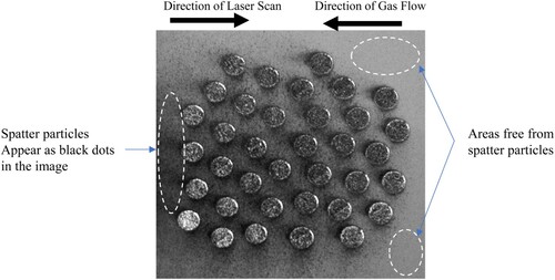
When multiple components are to be manufactured, the laser scan direction is from the left- to the right-hand side of the build plate. In addition, the laser scan direction is opposite to the direction of the gas flow, see . Hence, the accumulation of spattered powder particles on the left-hand side of the build plate is inevitable. The images of the powder bed after laser exposure confirm the above phenomenon and reveal a higher amount of spattered powder particles on the left-hand side of the build plate as compared to the right-hand side, see .
Figure 5. The laser scan sequence and path when multiple components are being manufactured on the build plate.
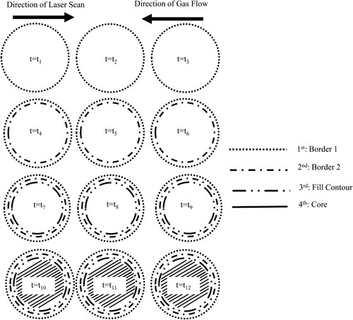
Figure 6. Top view image of the powder bed and the fatigue specimens. Spatter particles appear as black dots in the image and are more frequently found in the centre and towards the left-hand side of the build plate.
Spattered particles are more oxidised and significantly larger than the original virgin powder. Selective oxidation of Si and Mn has been observed on the surface of the spattered particles of 316 L stainless steel material [Citation17]. Although, a firm conclusion cannot be drawn from the results in , the data suggests that on average the specimens located on the utmost left-hand side of the build plate have a slightly higher oxygen content than those on the utmost right-hand side. This finding agrees with observations by Simonelli et al. [Citation17] and Liu et al. [Citation18].
The results of the defect analysis (plotted in ) clearly show a higher number of larger defects (i.e. > 500 µm2) in specimens fabricated on the left-hand side as compared to those on the right-hand side of the build plate. Although it is not possible to differentiate between oxide inclusions and porosity by image analysis, the result in (a) suggests that the spattered particles have a negative impact on fatigue strength.
Conclusions
The current study shows that the fatigue strength of parts manufactured by LPBF can vary depending on their location on the build plate. Examination of the laser scan path and sequence with respect to the direction of the gas flow reveals that the spattered particles are inevitably more accumulated on the left-hand side of the build plate. Spattered particles are more oxidised and consequently, specimens manufactured on the left-hand side have a slightly higher oxygen content and contain a higher number of large defects (i.e. defects larger than 500 µm2) as compared to those manufactured on the opposite side. Hence, as reported in this investigation, the specimens manufactured on the left-hand side of the build plate exhibit a lower fatigue strength as compared to those on the right-hand side.
Acknowledgements
Mr Anton Dahl-Jendelin is acknowledged for performing the examination of defects by image analysis.
Disclosure statement
No potential conflict of interest was reported by the author.
Additional information
Funding
Notes on contributors
Sepehr Hatami
Sepehr Hatami completed his MSc degree in materials processing at the Royal Institute of Technology (in Stockholm Sweden), and obtained his PhD degree in 2010 in the field of powder metallurgy from Chalmers University of Technology (Gothenburg, Sweden). After his PhD studies, Sepehr joined SKF, and worked in R&D as a welding process specialist. Since 2015, he has been part of the additive manufacturing group at RISE IVF (a Swedish research institute). Currently, his research is focused on the laser powder bed fusion process, and he is active in numerous nationally funded research projects both as a researcher and project manager.
References
- Dowling L, Kennedy J, O’Shaughnessy S, et al. A review of critical repeatability and reproducibility issues in powder bed fusion. Mater Des. 2020;186:1–17.
- Presley MA, Christensen PR. Thermal conductivity measurements of particulate materials: 5. Effect of bulk density and particle shape. J Geophys Res. 2010;115:1–13.
- Wang X, Kruth JP. Energy absorption and penetration in selective laser sintering: a ray tracing model. International Conference on Mathematical Modelling and Simulation of Metal Technologies; 2000, Nov 13–15; Ariel, Israel. p. 673–682.
- Fischer P, Romano V, Weber HP, et al. Sintering of commercially pure titanium powder with a Nd:YAG laser source. Acta Mater. 2003;51(6):1651–1662.
- Fischer P, Karapatis N, Romano V, et al. A model for the interaction of near-infrared laser pulses with metal powders in selective laser sintering. Appl Phys A. 2002;74:467–474.
- Qiu C, Panwisawas C, Ward M, et al. On the role of melt flow into the surface structure and porosity development during selective laser melting. Acta Mater. 2015;96:72–79.
- Khairallah SA, Anderson AT, Rubenchik A, et al. Laser powder-bed fusion additive manufacturing: physics of complex melt flow and formation mechanisms of pores, spatter, and denudation zones. Acta Mater. 2016;108:36–45.
- Gong H, Rafi K, Gu H, et al. Analysis of defect generation in Ti–6Al–4V parts made using powder bedfusion additive manufacturing processes. Addit Manuf. 2014;1:87–98.
- Abd-Elghany K, Bourell DL. Property evaluation of 304L stainless steel fabricated by selective laser melting. Rapid Prototyp J. 2012;18:420–428.
- Mower TM, Long MJ. Mechanical behavior of additive manufactured, powder-bed laser-fused materials. Mater Sci Eng A. 2016;651:198–213.
- Blinn B, Klein M, Gläßner C, et al. An investigation of the microstructure and fatigue behavior of additively manufactured AISI 316L stainless steel with regard to the influence of heat treatment. Metals. 2018;8(220):1–23.
- Shrestha R, Simsiriwong J, Shamsaei N, et al. Effect of build orientation on the fatigue behavior of stainless steel 316L manufactured via a laser powder bed fusion process. 27th Annual International Solid Freeform Fabrication Symposium – An Additive Manufacturing Conference; 2016, Aug 8–10; Austin, TX. p. 605–616.
- Hatami S, Ma T, Vuoristo T, et al. Fatigue strength of 316 L stainless steel manufactured by selective laser melting. J Mater Eng Perform. 2020;29:3183–3194.
- Zhang M, Sun C-N, Zhang X, et al. Predictive models for fatigue property of laser powder bed fusion stainless steel 316L. Mater Des. 2018;145:42–54.
- Pal S, Gubeljak N, Bončina T, et al. The effects of locations on the build tray on the quality of specimens in powder bed additive manufacturing. Int J Adv Manuf Technol. 2021;112:1159–1170.
- International Organization for Standardization (ISO). Metallic materials – verification of the alignment of fatigue testing machines, 2012. Standard No. ISO 23788.
- Simonelli M, Tuck C, Aboulkhair NT, et al. A study on the laser spatter and the oxidation reactions during selective laser melting of 316L stainless steel, Al-Si10-Mg, and Ti-6Al-4V. Metall Mater Trans A. 2015;46:3842–3851.
- Liu Y, Yang Y, Mai S, et al. Investigation into spatter behavior during selective laser melting of AISI 316L stainless steel powder. Mater Des. 2015;87:797–806.