
ABSTRACT
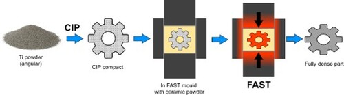
A novel, two-step, solid-state method to produce complex geometry titanium parts was investigated by combining Cold Isostatic Pressing (CIP) with Field Assisted Sintering Technology (FAST). Hydride-dehydride powders of commercially pure titanium and Ti-6Al-4V were CIP’ed into shaped compacts using silicone moulds, then further consolidated using FAST, with ZrO2 powder as a secondary pressing media. The final parts retained the complex features from the CIP moulds but were compressed in the pressing axis. Densities >99% were achieved, with optimised FAST processing parameters required for the different alloys. High hardness and fine equiaxed microstructures were observed at the edges of the parts, suggesting oxygen transfer from the ZrO2 pressing media had occurred, with more investigation needed to better understand and prevent this. Despite this, the CIP-FAST process route has been demonstrated to be a fast, low-cost and material-efficient option to produce a wide variety of complex titanium parts.
GRAPHICAL ABSTRACT
Introduction
Powder metallurgy (PM) techniques have proven to be incredibly valuable and versatile for the manufacturing of complex geometry parts from a wide range of alloys, with low material wastage. PM has been used to produce near net shape titanium parts for several decades, but has been restricted to niche, low-volume applications [Citation1].
Limited adoption is a result of both the high cost of Ti powders relative to other metals and limitations on the types of PM technologies which can be used effectively. PM components often exhibit inferior mechanical properties when compared to conventionally processed material. This can be due to a variety of factors, including undesirable microstructures and texture, as well as the presence of porosity. For example, parts made by additive manufacturing (AM) techniques often contain porosity and anisotropic mechanical behaviour resulting from the formation of elongated columnar grains in the build direction, both of which can cause reduced ductility and fatigue strength [Citation2]. Although these issues can be prevented by altering printing parameters, there are challenges in finding processing parameters for consistent results across different geometries. Pressureless sintering techniques require relatively high temperatures and long sintering times to achieve high relative densities for Ti alloys. This causes significant grain growth to occur, leading to the formation of coarse lamellar microstructures in α+β alloys such as Ti-6Al-4V, resulting in poor fatigue performance which is unsuitable for many aerospace applications [Citation3,Citation4]. One way to mitigate this is by using very fine powders, as smaller particle sizes are easier to sinter. In metal injection moulding (MIM), <45 µm spherical powders are typically used for Ti, however these are more expensive and finer powders tend to have higher oxygen content due to larger surface area [Citation5]. Despite the use of fine powders, MIM parts often still contain some porosity, and so further processing by shot peening or hot isostatic pressing (HIP) is required if the parts are to be used in applications where fatigue resistance is important [Citation5,Citation6]. Additional HIP processing of AM or MIM parts further increases their cost, limiting their parts for use in high-value sectors only.
Field Assisted Sintering Technology (FAST) is a solid-state PM technique which is capable of effectively consolidating a wide range of materials, including Ti alloys [Citation7]. FAST has several benefits over other PM technologies, including:
High relative densities achievable through simultaneous application heat and pressure
High heating rates and short processing times, preventing excessive grain growth and retaining fine microstructures
Energy efficiency due to direct heating of the tooling and/or sample, rather than using external heating elements as in hot pressing and HIP
Flexibility with regard to powder particle size and morphology, allowing for use of cheaper sources of powder, or even machining swarf [Citation8].
Despite these benefits, there are limitations on the geometries which can be produced directly. FAST is typically done by placing powder into a graphite ring mould, resulting in discs or cylinders of consolidated material. Although graphite is a very suitable material for FAST, due to its high-temperature capabilities (up to 2400°C) and electrical conductivity, it is prone to brittle failure if high forces are applied. This makes use of shaped graphite moulds challenging as stress concentrations can lead to premature mould failure, whereas a standard circular circumference allows for even distribution of the applied force, mitigating this. Discs and cylinders are acceptable for some purposes, such as small-scale assessments of new materials, or to make plates for ballistic testing; however, are not generally useful directly in their as-FAST form. Subsequent processes, such as cutting, machining and forging, are required to produce tessellating tiles or final components. This inevitably results in higher costs and wasted material, which is undesirable.
Several approaches to direct production of shaped parts from powder using FAST have previously been demonstrated. One approach is to use shaped tooling to produce parts with two parallel surfaces, such as flat dog-bone specimens for tensile testing [Citation9]. More complex parts have also been produced using customised graphite tooling, for example, a near-net shape TiAl turbine blade was made using an assembly of graphite parts [Citation10]. This approach inevitably leads to different regions of the part experiencing different temperatures and/or pressures, likely resulting in leading to heterogeneous part density and microstructure. ‘Sacrificial’ powders which only partially densify relative to the material being processed have been investigated to solve this issue [Citation11]. Another approach was developed, termed the ‘deformed interface method’, which uses a layer of another material to separate the powder into regions with a defined shape. For example, graphite foil can be placed within the powder inside a standard mould in such a way as to create two different parts which together make up the volume of the mould [Citation12,Citation13].
French company Norimat has patented a technique for the production of complex components by first using 3D printing to create a precursor green part, then surrounding it with a sacrificial powder before FAST processing [Citation14]. Green parts are produced using a technique such as binder jetting, followed by debinding to produce a low-density brown part. The brown part is then placed into a standard graphite mould along with the sacrificial powder. FAST processing within the sacrificial powder causes the brown part to sinter and while retaining its shape, although it is slightly compressed in the pressing direction due to non-isostatic pressure. The final part is then demoulded from the sacrificial powder. This process is more versatile than the others because 3D printing allows for easy part design, even accounting for the compression during FAST, and no custom FAST tooling is required.
In this study, we investigate CIP-FAST, a similar method to that developed by Norimat, but the precursor part is produced by cold isostatic pressing (CIP) of powders, rather than by using a 3D printing process. This has a few benefits, such as reduced number of processing steps, being able to use cheaper sources of powder such as from the hydride dehydride (HDH) process [Citation15] rather than fine spherical powders used in processes like binder jetting [Citation16], and no use of binder.
Although part geometry is more limited using CIP compared to 3D printing, relatively complex shapes can be produced and then sintered to high density, with minimal machining required [Citation17]. CIP has been successfully combined with hot isostatic pressing (HIP) before to create near net shape Ti components, as demonstrated by Dynamet’s CHIP (Cold-Hot isostatic pressing) process [Citation18]. HDH Ti powders are compacted into shapes using reusable elastomeric tooling, then vacuum sintered to achieve a density where there is no longer any interconnected porosity. The material is then HIP’ed to full density, without requiring encapsulation [Citation19]. Replacing the vacuum sintering and HIP steps with FAST not only reduces the number of processing steps, but also the processing time and energy consumption, due to higher heating rates and direct heating of the tooling instead of external induction heating.
CIP has previously been combined with FAST to process Al2O3 and WC-Co powders, however this involved presintering and laser machining a CIP cylinder prior to FAST processing [Citation20]. In CIP-FAST, a shaped mould is used during CIP to generate a complex geometry compact, which is then directly processed using FAST.
An important consideration for CIP-FAST is the choice of surrounding powder, acting as a secondary pressing media during FAST processing. The material ideally should not react with the Ti and only partially sinter so that it can easily be broken away from the part after processing. Ceramic powders usually require high sintering temperatures, well above those typically used for Ti alloys. For example, one study showed that when processing ZrO2 powder with FAST using a temperature of 1000°C and a pressure of 100 MPa for 15 min, a relative density of around 75% was reached [Citation21]. Meanwhile, these conditions would be expected to consolidate Ti alloy powders to full density [Citation7]. Norimat discuss the use of various ZrO2 and Al2O3 based powders for their process [Citation14]. These materials are favourable when one considers their Gibbs free energy of formation (ΔGf) relative to TiO2. shows that the formation of both ZrO2 and Al2O3 have a more negative Gibbs free energy than TiO2, meaning that they have higher stability and greater affinity for oxygen. Therefore, oxygen pickup by Ti is expected to be limited when using these ceramic powders. SiO2 is unsuitable due to more positive ΔGf values than TiO2, and the higher cost of Y2O3 makes it less appealing to use, despite having the most negative ΔGf values. Therefore, ZrO2 was chosen for this study for its balance of relative stability and low cost.
Figure 1. Ellingham diagram showing temperature dependant Gibbs free energy of formation (ΔGf) for various metal oxides over temperature range typically used for FAST processing of Ti powders. Calculated using data from [Citation22,Citation23].
![Figure 1. Ellingham diagram showing temperature dependant Gibbs free energy of formation (ΔGf) for various metal oxides over temperature range typically used for FAST processing of Ti powders. Calculated using data from [Citation22,Citation23].](/cms/asset/e6f4638a-9716-4202-bca8-da35fe667fe4/ypom_a_2236907_f0001_ob.jpg)
Materials and methods
Commercially pure (CP) titanium (Grade 1) and Ti-6Al-4V (Grade 5) hydride-dehydride (HDH) powders (Phelly Materials Inc., U.S.A.), with nominal particle size ranges of 45–150 µm were used. The chemical composition of the powders provided by the supplier, is listed in . (c) shows a particle size range of approximately 50–250 µm, as measured by laser diffraction using a Malvern Mastersizer 3000, with a mean average of 10 measurements taken. The CP-Ti powder particles were smaller on average, despite being labelled as the same size fraction, possibly due to being more easily broken up when in hydride form. also displays the angular particle morphologies resulting from milling during the HDH process.
Figure 2. Secondary electron micrographs of (a) CP-Ti powder and (b) Ti-6Al-4V powder, (c) measured particle size distribution of both powders.
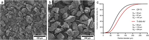
Table 1. Chemical composition of CP-Ti and Ti-6Al-4V powders used in this study.
To produce complex-shaped parts, a mass of 50 g of powder was poured into off-the-shelf silicone moulds and sealed with a sheet of silicone. The moulds were then placed into rubber bags and the air was evacuated using a vacuum pump. The bags were placed into the pressure chamber of an AIP CP360 CIP and the chamber closed. Processing conditions were based on previous research with similar HDH Ti powders [Citation20]. The wet bag method was used, with the pressure ramped up to a maximum of 350 MPa, where it was held for 2 min, then slowly released back to atmospheric pressure. The bags were then removed from the chamber and the resulting compacts were extracted from the moulds.
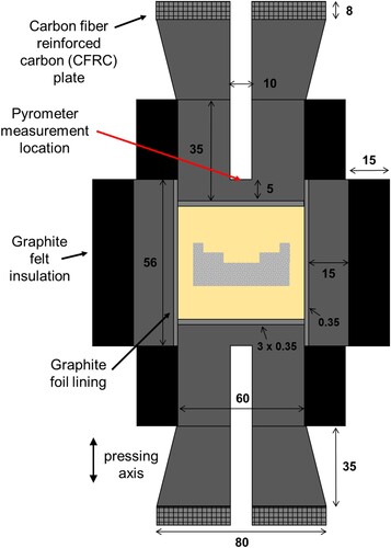
The compacts were placed into a 60 mm internal diameter graphite mould along with 170 g of calcined ZrO2 powder (>99%, Alfa Aesar, D50 = 1.5 µm). shows the tooling setup, with the compact being fully covered with ZrO2 and located centrally within the mould, preventing any contact with the graphite tooling during processing. The tooling was pressed at 5 MPa in a benchtop hydraulic press before being placed in the FAST vessel. Graphite felt and carbon fibre reinforced carbon plates were added to improve power efficiency and improve temperature homogeneity [Citation24,Citation25]. FAST processing was done using an FCT Systeme GmbH type HP D 25 furnace. Heating was programmed in two stages, first using a 100°C min−1 heating rate to 900°C, followed by a rate of 25°C min−1 up to 980°C to reduce temperature overshoot. The temperature was measured by a vertically mounted optical pyrometer, focussed on a location 5 mm away from the surface of the material, made possible through a hole machined in the graphite tooling (as seen in ). A low pressure of 5 MPa (14 kN) was applied during the first heating stage to prevent damage of the fragile CIP compacts, before being increased to 35 MPa (99 kN) during the second stage. These conditions were then held for the desired dwell time, after which the current was stopped, allowing free cooling to room temperature. After removal from the tooling, the partially sintered ZrO2 surrounding the Ti part was broken away using a hammer, and any residual ZrO2 present on the surfaces was removed by abrasive grit blasting.
Figure 3. Cross-sectional diagram of CIP compact within graphite FAST tooling setup. Dimensions in mm.
The parts were sectioned to reveal a cross section from the edge to the centre, followed by metallographic preparation using SiC grit papers and 0.06 µm colloidal silica suspension. A Nikon Eclipse LV150 light microscope was used with polarising filters to collect micrographs for microstructural analysis. A FEI Inspect F50 scanning electron microscope (SEM) was used for further microscopy in backscattered and secondary electron modes, along with an Oxford Instruments attachment for chemistry analysis by energy dispersive X-ray spectroscopy (X-EDS).
Densities of both the CIP compacts and final parts were measured using the Archimedes principle with a Mettler Toledo density meter. Image analysis using thresholding in ImageJ to isolate the porosity was used on three micrographs per CIP sample, with the mean average relative density reported.
Vickers hardness was measured on the polished surfaces using a ZwickRoell Durascan-80. A force of 1 kg (HV1) was applied for 15 s per indent. Indents were done at the edges of the parts, diagonally at a 22.5° angle relative to the edge, with each indents spaced 0.4 mm across and 0.2 mm down.
Results and discussion
The effect of alloy composition and powder morphology during the CIP stage
The CIP conditions caused the powder particles in both CP-Ti and Ti-6Al-4V to bond together sufficiently to create compacts which remained intact and easy to handle for further processing after removal from the moulds. shows the significant void volume remaining in both compacts, with the density values in use of CP-Ti resulting in a higher relative density than Ti-6Al-4V. Image analysis of several micrographs, including those in , confirmed accuracy of the Archimedes densities. The lower strength of CP-Ti compared to Ti-6Al-4V caused greater particle deformation to occur during CIP, resulting in a higher relative density being achieved. The CP-Ti particles deformed around each other and become more rounded, whereas the Ti-6Al-4V particles remained angular with sharp edges.
Figure 4. Light micrographs of CIP compact cross section, (a) CP-Ti, (b) Ti-6Al-4V.
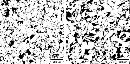
Table 2. Measured Archimedes density and calculated relative density of parts after different processing.
Additional trials using spherical Ti-6Al-4V powders produced by electrode induction gas atomisation were unsuccessful, with no compaction occurring. This was unsurprising, due to poor packing density and minimal surface contact of spherical particles, although using blends of spherical and angular powders may allow production of compacts which can be further processed.
shows the CIP compacts after removal from the moulds, with the greater deformation of the CP-Ti powder resulting in better definition of the mould features compared to the Ti-6Al-4V compact. This suggests that a higher applied pressure during CIP may be required to improve the detail retained in higher-strength alloys. It was also noticeable that the silicone mould used for Ti-6Al-4V was slightly damaged on removal of the compact, and small amounts of silicone had been caught by the powder particles. Alternative CIP mould material is therefore required for higher strength alloys, both to allow for mould reuse and prevent contamination of the parts.
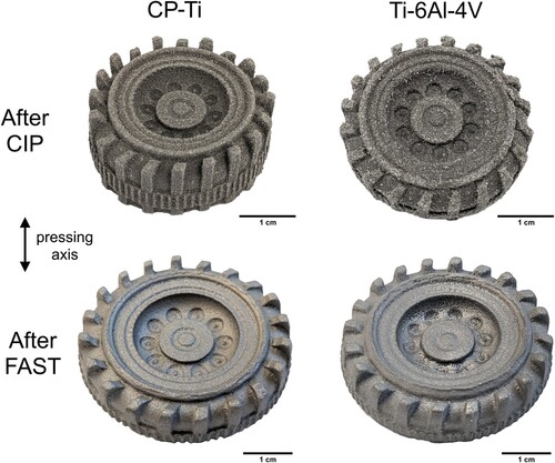
Figure 5. Photographs of CP-Ti and Ti-6Al-4V CIP-FAST parts before and after FAST processing at 980°C for 10 min.
Microstructure evolution during the FAST process
FAST processing caused the parts to be compressed in the pressing axis and stretched uniformly normal to the pressing axis (). The largest measured diameter increased by 7% for CP-Ti and 8% for Ti-6Al-4V parts, whereas the height decreased by 38% for CP-Ti and 42% for Ti-6Al-4V. This nonuniform deformation was expected due to the uniaxial application of force in FAST, rather than isostatic pressure used in HIP. Despite this, both parts retained the complex geometry from the initial CIP mould, with better definition seen in the CP-Ti part resulting from the CIP process. Both parts were close to full theoretical density (), demonstrating that the FAST processing had successfully sintered the compacts.
Optical micrographs in reveal the microstructural variations at different locations within the parts. The majority of the CP-Ti part exhibited a microstructure consisting of coarse α grains, resulting from grain growth which occurs when processing well above the β-transus (around 888°C for Grade 1), similar to as seen in other studies [Citation26]. There was no distinctive difference from the centre of the part (location A) towards the radial edge (location B). A roughly 500 µm layer of much finer, equiaxed grains was present uniformly around the edge (location C), however, indicating that the material at the edges experienced a different temperature and/or was affected by interactions with the surrounding ZrO2.
Despite 980°C being below the β-transus of Ti-6Al-4V (around 995°C), the transformed β microstructure reveals that the actual temperature experienced was supertransus. This shows that there was a significant temperature deviation between where the location measured by the pyrometer and the material inside the mould. Therefore, in future, a lower programmed temperature would be required for subtransus processing. A finer microstructure was observed towards the radial edge of the wheel, indicating it had experienced different thermal history. It is likely that a temperature gradient was present across the part during FAST processing. The low electrical conductivity of ZrO2 caused the current to flow preferentially through the graphite mould, leading to higher temperature at the radial edge as it is close to the mould. The cooling rate also will have differed, with slower cooling expected in the centre due to further distance from the water-cooled electrodes and thermal insulation provided by the surrounding ZrO2. In this case, the finer α laths observed in location B of suggest the cooling rate was most influential in causing the microstructural variation.
A layer approximately 800 µm thick with a much finer microstructure and containing considerable porosity was visible in the Ti-6Al-4V part, explaining the lower relative density compared to CP-Ti. This also suggests that the material at the edges may have experienced different conditions or was affected by interactions with the surrounding ZrO2. Silicone contamination from the CIP mould may have also affected this region.
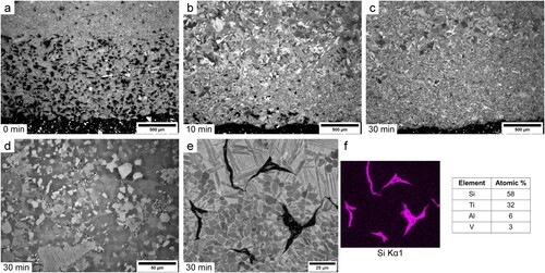
To investigate the sintering behaviour of Ti-6Al-4V compacts further, additional parts were processed using varying dwell times at 980°C. shows how the porosity at the edge decreases over time, until essentially none remains after 30 min. The layer of fine microstructure remains, however, meaning that prevention of grain growth by porosity was not the major cause of this. At higher magnification another phase was visible which seemed to be present on the surfaces of the original powder particles. X-EDS analysis in (f) determined this phase to be composed mostly of Si, with the stoichiometry suggesting the phase was TiSi2. This confirms that significant contamination of silicone from the CIP mould occurred as it is the only source of Si during processing and visual inspection of the CIP compacts showed some of the mould material on the surface of the Ti-6Al-4V compacts. It is unclear exactly how the silicone behaved during FAST processing, however it seems to have reacted with the Ti and formed a phase which acted as a barrier between powder particles, preventing diffusion between particles and grain growth.
Figure 6. Cross polarised light micrographs of CP Ti and Ti-6Al-4V parts at different locations after FAST processing at 980°C for 10 min.
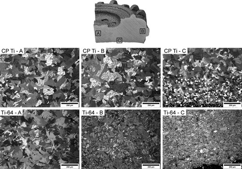
Figure 7. (a–d) Cross polarised light micrographs of Ti-6Al-4V parts (at edge location A from ) with varying dwell time at 980°C. (e) Backscattered electron micrograph of similar region to (d), with corresponding Si X-EDS map and spectra of Si containing phase (f).
A different geometry mould made from a higher hardness silicone grade was then used for comparison and to demonstrate the production of alternative parts via CIP-FAST. Ti-6Al-4V powder was used and processed at 980°C for 30 min to ensure full relative density. (b) shows the part before and after FAST processing, with deformation once again in the pressing axis, despite good retention of the features. Some cracks were visible in the final part which are expected to have occurred during the early stages of FAST processing when the compact is still fragile. More severe cracking was observed during other experiments using initial pressures greater than 5 MPa, suggesting that low pressure is crucial at this stage. The geometry and orientation of the part relative to the pressing axis could also have had an impact, due to potential stress concentrations in particular areas, as occurred in thin neck and muzzle regions.
Figure 8. (a) Diagram indicating orientation of CIP compact in FAST tooling, (b) photograph of Ti-6Al-4V compact using higher hardness silicone CIP mould and resulting FAST part after processing at 980°C 30 min, (c) cross polarised light micrograph of Ti-6Al-4V part centre (d + e) edge, (f) backscattered electron micrograph of similar edge region to (e).
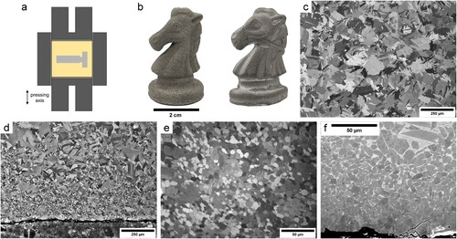
(c) shows that a similar microstructure was obtained in the centre of the part to those previously (Ti-6Al-4V location A in ). A different layer at the edge was once again visible ((d)), however different to that seen with the previous mould ((c)). No other phase was visible, indicating that Si contamination had successfully been prevented using the harder silicone. A fine microstructure was present, similar to that observed in the CP-Ti part in . The most likely explanation for the microstructural variation seen at the edges is oxygen transfer from the ZrO2 during FAST processing. Oxygen is a strong α phase stabiliser, therefore increases the β transus temperature. This could have prevented the edge regions from transforming, leading to retention of fine primary α present in the powder. Oxygen also acts as a grain refiner, supporting this theory [Citation27].
(e) shows how the amount of β and secondary α is reduced towards the edge of the part, which is consistent with α stabilisation from oxygen diffusion. Some microcracks are also visible at the edge, possibly formed during metallographic preparation, indicating that this region is relatively brittle. This is similar to the effect of alpha case, which is often observed in titanium alloy components after processing and is often removed by chemical milling before using fatigue-sensitive applications [Citation28]. Unfortunately, attempts at X-EDS analysis to measure oxygen content across this region were unsuccessful due to difficulties in analysing light elements with this technique.
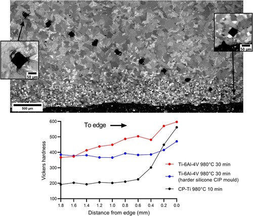
Microhardness was measured across the edge of the parts as hardness can be a good indicator of oxygen content in Ti alloys. Oxygen has a substantial effect on the strength, and therefore hardness, of Ti alloys, with the tensile strength of CP-Ti increasing from 240 MPa to 550 MPa from grade 1 (max 0.18 wt-% oxygen) to 4 (max 0.4 wt-% oxygen) under identical processing conditions [Citation29]. shows how the Vickers hardness indents are smaller in the edge layer, which corresponds to higher hardness values. For the CP-Ti part, hardness increased from around 200 to over 500 HV. When comparing to literature studies on the effect of oxygen content on hardness, this suggests that contents were considerably higher than 4000 ppm [Citation30,Citation31]. Although the effect was not as severe for the Ti-6Al-4V parts, a noticeable increase in hardness was still observed. Studies on alpha case in Ti-6Al-4V show similar increases in hardness toward the edge, with hardness values exceeding 600 HV and oxygen contents up to the solubility limit of 14.5 wt-% possible [Citation32]. There was less of an effect in the part made using the more rigid silicone mould, highlighting the additional impact of the thick layer of Si contamination.
Figure 9. (a) Cross polarised light micrograph of CP Ti part showing Vickers hardness indents towards edge, (b) Vickers hardness values for CP Ti and Ti-6Al-4 V parts towards edge.
Conclusions
This study has shown that combining CIP and FAST provides a promising route to produce complex titanium components from powder, with many benefits over existing PM routes such as high relative density, short processing times, use of cheaper HDH powder, and no material wastage.
Although FAST processing caused the parts to be deformed non-uniformly, CIP moulds could be specifically designed to account for this. Modelling could be used to predict the deformation of CIP compacts during FAST processing. A better understanding of temperature is also required through modelling, to prevent variation between the measured temperature and that experienced by the part, as well as thermal gradients normal to the pressing axis. The silicone mould material used in this study was not ideal, due to Si contamination, however alternative materials can prevent this issue. Despite considering the relative stabilities of TiO2 and ZrO2, it seems that significant oxygen transfer occurred during the FAST processing, causing layers of fine microstructure and high hardness to develop, which could cause problems such as poor fatigue performance, depending on the application of the component. Use of an alternative secondary pressing media could reduce or prevent this issue in future, with more investigation required.
There is also potential to use larger scale FAST equipment for processing larger CIP compacts, or even multiple at once, making CIP-FAST more appealing for industrial scale component production. At present, FAST tooling up to 600 mm in diameter is being used, and the technology continues to be developed [Citation33]. Larger scale CIP equipment already exists, with vessel diameters up to 3 m available from one supplier [Citation34]. The reusability of the CIP moulds and FAST tooling will also keep the process cost-effective on larger scales, and the ceramic powder could easily be ground back to powder for reuse.
The ability to use angular powders makes CIP-FAST quite different from many other PM titanium approaches which require spherical powders. In addition to HDH powders, Kroll sponge fines, milled titanium swarf and powders from unconventional extraction processes such as the FFC Cambridge process, could be used directly without spheroidisation [Citation35,Citation36]. CIP-FAST could also be used to create multi-alloy components, in a similar way to how FAST has been used previously for diffusion bonding [Citation37].
Disclosure statement
No potential conflict of interest was reported by the author(s).
Additional information
Funding
References
- Froes FH. 8 – Powder metallurgy of titanium alloys. In: I Chang, Y Zhao, editors. Advances in powder metallurgy. Woodhead; 2013. p. 202–240. doi:10.1533/9780857098900.2.202
- Childerhouse T, Jackson M. Near net shape manufacture of titanium alloy components from powder and wire: a review of state-of-the-art process routes. Metals (Basel). Jun. 2019;9(6):689. doi:10.3390/met9060689
- Fang ZZ, Paramore JD, Sun P, et al. Powder metallurgy of titanium – past, present, and future. Int Mater Rev. Aug. 2017: 1–53. doi:10.1080/09506608.2017.1366003
- Wang H, Fang ZZ, Sun P. A critical review of mechanical properties of powder metallurgy titanium. Int J Powder Metall. 2010;46(5):14.
- Dehghan-Manshadi A, Bermingham M, Dargusch MS, et al. Metal injection moulding of titanium and titanium alloys: challenges and recent development. Powder Technol Sep. 2017;319:289–301. doi:10.1016/j.powtec.2017.06.053
- Ebel T. Metal injection molding (MIM) of titanium and titanium alloys. In: Handbook of metal injection molding. Elsevier; 2012. p. 415–445. doi:10.1533/9780857096234.4.415
- Weston NS, Derguti F, Tudball A, et al. Spark plasma sintering of commercial and development titanium alloy powders. J Mater Sci Jul. 2015;50(14):4860–4878. doi:10.1007/s10853-015-9029-6
- Weston NS, Jackson M. FAST-forge of titanium alloy swarf: a solid-state closed-loop recycling approach for aerospace machining waste. Metals (Basel). Feb. 2020;10(2):296. doi:10.3390/met10020296
- Arnaud C, Manière C, Chevallier G, et al. Dog-bone copper specimens prepared by one-step spark plasma sintering. J Mater Sci. Nov. 2015;50(22):7364–7373. doi:10.1007/s10853-015-9293-5
- Voisin T, Monchoux J-P, Durand L, et al. An innovative way to produce γ-TiAl blades: spark plasma sintering: an innovative way to produce γ-TiAl blades. Adv Eng Mater. Oct. 2015;17(10):1408–1413. doi:10.1002/adem.201500019
- Manière C, Durand L, Weibel A, et al. A sacrificial material approach for spark plasma sintering of complex shapes. Scr Mater. Nov. 2016;124:126–128. doi:10.1016/j.scriptamat.2016.07.006
- Manière C, Nigito E, Durand L, et al. Spark plasma sintering and complex shapes: the deformed interfaces approach. Powder Technol Oct. 2017;320:340–345. doi:10.1016/j.powtec.2017.07.048
- Manière C, Torresani E, Olevsky E. Simultaneous spark plasma sintering of multiple complex shapes. Materials (Basel). Feb. 2019;12(4):557. doi:10.3390/ma12040557
- Beynet Y, Epherre R. Method for manufacturing a part of complex shape by pressure sintering starting from a preform, Patent EP 3 860 785 B1, 2021.
- McCracken CG, Barbis DP, Deeter RC. Key characteristics of hydride–dehydride titanium powder. Powder Metall Jul. 2011;54(3):180–183. doi:10.1179/174329011X13045076771849
- Mostafaei Elliott A, Amy M, Barnes JE, et al. Binder jet 3D printing – process parameters, materials, properties, modeling, and challenges. Prog Mater Sci. Jun. 2021;119:100707. doi:10.1016/j.pmatsci.2020.100707
- Attia UM. Cold-isostatic pressing of metal powders: a review of the technology and recent developments. Crit Rev Solid State Mater Sci. Nov. 2021;46(6):587–610. doi:10.1080/10408436.2021.1886043
- Abkowitz SM, Abkowitz S, Fisher H. Breakthrough claimed for titanium PM. Met Powder Rep. Nov. 2011;66(6):16–21. doi:10.1016/S0026-0657(12)70015-2
- Abkowitz S, Abkowitz S, Fisher H. Titanium alloy components manufacture from blended elemental powder and the qualification process. In: Titanium powder metallurgy. Elsevier; 2015. p. 299–312. doi:10.1016/B978-0-12-800054-0.00017-4
- Hocquet S, Dupont V, Cambier F, et al. Densification of complex shape ceramics parts by SPS. J Eur Ceram Soc. Jul. 2020;40(7):2586–2596. doi:10.1016/j.jeurceramsoc.2019.10.038
- Bernard-Granger G, Guizard C. Spark plasma sintering of a commercially available granulated zirconia powder: I. Sintering path and hypotheses about the mechanism(s) controlling densification. Acta Mater Jun. 2007;55(10):3493–3504. doi:10.1016/j.actamat.2007.01.048
- Robie RA, Hemingway BS. Thermodynamic properties of minerals and related substances at 298.15 K and 1 bar (10^5 pascals) pressure and at higher temperatures, vol. U.S. Geological Survey Bulletin 2131. United States GovernmentPrinting Office, 1995. doi:10.3133/b2131
- Vasant Kumar R, Chivall J, Brook D. ‘The interactive Ellingham diagram,’ The interactive Ellingham diagram. [cited May 10, 2023]. Available from: https://www.doitpoms.ac.uk/tlplib/ellingham_diagrams/interactive.php.
- Laptev AM, Hennicke J, Ihl R. Influence of CFRC insulating plates on spark plasma sintering process. Metals (Basel). Feb. 2021;11(3):393. doi:10.3390/met11030393
- Laptev AM, Bram M, Vanmeensel K, et al. Enhancing efficiency of field assisted sintering by advanced thermal insulation. J Mater Process Technol. Dec. 2018;262:326–339. doi:10.1016/j.jmatprotec.2018.07.008
- Miklaszewski A, Garbiec D, Niespodziana K. Sintering behavior and microstructure evolution in cp-titanium processed by spark plasma sintering. Adv Powder Technol. Jan. 2018;29(1):50–57. doi:10.1016/j.apt.2017.10.010
- Wasz ML, Brotzen FR, McLellan RB, et al. Effect of oxygen and hydrogen on mechanical properties of commercial purity titanium. Int Mater Rev. Jan. 1996;41(1):1–12. doi:10.1179/imr.1996.41.1.1
- Deshmukh V, Kadam R, Joshi SS. Removal of alpha case on titanium alloy surfaces using chemical milling. Mach Sci Technol. Apr. 2017;21(2):257–278. doi:10.1080/10910344.2017.1284558
- Donachie MJ. Introduction to selection of titanium alloys. In: Titanium: a technical guide. ASM International; 2000. p. 5–11. doi:10.31399/asm.tb.ttg2.t61120005
- Gardner HM, Gopon P, Magazzeni CM, et al. Quantifying the effect of oxygen on micro-mechanical properties of a near-alpha titanium alloy. J Mater Res. Jun. 2021;36(12):2529–2544. doi:10.1557/s43578-020-00006-3
- Oh J-M, Lee B-G, Cho S-W, et al. Oxygen effects on the mechanical properties and lattice strain of Ti and Ti-6Al-4 V. Met Mater Int. Oct. 2011;17(5):733–736. doi:10.1007/s12540-011-1006-2
- Gaddam R, Sefer B, Pederson R, et al. Study of alpha-case depth in Ti-6Al-2Sn-4Zr-2Mo and Ti-6Al-4 V. IOP Conf Ser Mater Sci Eng. Dec. 2013;48:012002. doi:10.1088/1757-899X/48/1/012002
- Ilevbare G. INL advanced manufacturing capabilities. Idaho National Laboratory, Aug. 2022. [cited May 03, 2023]. [Online]. Available from: https://inldigitallibrary.inl.gov/sites/sti/sti/Sort_63335.pdf.
- Quintus Technologies. Cold Isostatic Pressing (CIP) Systems. [cited May 11, 2023]. Available from: https://quintustechnologies.com/cold-isostatic-pressing/products/cold-isostatic-presses/.
- Sutherland AE. Sustainable Recycling of Metal Machining Swarf via Spark Plasma Sintering [master's thesis]. Colorado State University, United States; 2021.
- Chen GZ, Fray DJ, Farthing TW. Direct electrochemical reduction of titanium dioxide to titanium in molten calcium chloride. Nature. Sep. 2000;407(6802):361–364. doi:10.1038/35030069
- Pope JJ, Calvert EL, Weston NS, et al. FAST-DB: a novel solid-state approach for diffusion bonding dissimilar titanium alloy powders for next generation critical components. J Mater Process Technol. Jul. 2019;269:200–207. doi:10.1016/j.jmatprotec.2019.02.011