
 ?Mathematical formulae have been encoded as MathML and are displayed in this HTML version using MathJax in order to improve their display. Uncheck the box to turn MathJax off. This feature requires Javascript. Click on a formula to zoom.
ABSTRACT
Gas exchange between soil and atmosphere governs the growth of plants and global circulation of the gaseous component of air. Enhancement of gas exchange by wind has been reported in media with large pores. In clayey paddy fields, large aggregates (clods) and inter-aggregate pores are prone to be formed by tillage. However, the effect of wind on gas transport has not been considered in such fields. This study quantified the wind-induced gas movement through the paddy soil layer composed of large clods. The applicability of the analysis using the gas diffusion equation was also verified regarding the mean clod size and wind condition. Undisturbed soil columns were taken from the ‘poorly tilled’ and ‘fairly tilled’ paddy field under the cultivation of soybean. The mean diameters of the clods were 3.4 and 1.9 cm for the ‘poorly’ and ‘fairly’ tilled columns, respectively. A repacked silica sand column was also prepared as a reference. Diffusion tests were conducted for the columns in the field under natural wind and in the laboratory under calm conditions, with CO2 as a purge gas and atmospheric oxygen as a tracer gas. The gas transfer efficiency was evaluated by and
, which is the ratio of the time until the oxygen concentration reaches 50% and 90% of that in the atmosphere in the field to that in the laboratory, respectively. The results showed that gas transfer through the paddy soil layers, comprised a few centimeters of clods, under natural wind was up to 11 times quicker than under the calm conditions. The wind-induced gas exchange remained at maximum under the wind speed of more than 1.2 m s−1 at 20 cm above the soil surface in the poorly tilled soil. In contrast, in the fairly tilled soil, the effect of wind gradually increased with wind speed and finally became close to that in the poorly tilled soil at the wind speed around 2.0 m s−1. The applicability of the gas diffusion equation deteriorated as the wind speed increased from 1.2 to 2.6 m s−1 or the mean aggregate size increased from 1.9 to 3.4 cm.
1. Introduction
The processes of gas exchange between the soil and the atmosphere affect not only biomass production but they are also important from the environmental perspective (Stępniewski, Stępniewska, and Rożej Citation2011). As an importance in crop production, oxygen exchange supports the respiration of crop roots, and water vapor transfer controls the water content near the dry soil surface, which destines the germination of crop seeds. Simultaneously, the emission of greenhouse gases, such as methane or nitrous oxide from cultivated soil to the atmosphere is also controlled by the transfer rate through the soil layer.
Although gaseous transfer in the soil can occur by several mechanisms (Hillel Citation1998), gas movement in the soil is usually regarded as a process of molecular diffusion because the importance of other mechanisms, such as mass flow, aerodynamic dispersion, or the pressure fluctuation of air, are relatively very low. By combining Fick’s law and the equation of continuity, the gas diffusion equation is obtained to yield solutions for the temporal distribution of gas concentration (Fujikawa and Miyazaki Citation2005). Numerous applications of the gas diffusion equation or the diffusion coefficient to the analysis of gas exchange between the soil and the atmosphere are found in soil science, crop science, civil engineering, earth science, etc.
In contrast, researchers have demonstrated that wind enhances the gas movement in highly permeable porous media. Studies on wind-induced gas transport in soil have a history of more than a half-century. Fukuda (Citation1955) and Farrell, Greacen, and Gurr (Citation1966) have left pioneering theoretical works on this phenomenon. Because the air velocity in soil follows Darcy’s law, the parabolic partial differential equation with respect to the air pressure becomes the fundamental equation for this phenomenon. Fukuda (Citation1955) solved the equation assuming an infinitesimal boundary. However, Farrell, Greacen, and Gurr (Citation1966) analyzed the situation with the bottom of permeable soil at a finite depth, presenting that wind gustiness had a higher effect on the air movement than the infinitesimal case. Scotter and Raats (Citation1969) extended these studies to the relationship between oscillating air movement and the hydrodynamic dispersion of water vapor. Ishihara, Shimojima, and Harada (Citation1992) later differentiated the type of wind-induced gas transport. They showed ‘pressure pumping’ as the major mechanism in a porous material with low air permeability, such as sand with a particle diameter of 0.2 or 0.5 mm. Simultaneously, aerodynamic dispersion dominates in porous materials with high air permeability, such as glass beads with a particle diameter of 10 mm. They also showed both mechanisms can be described in the form of Fick’s law.
Although numerous studies in the field support the validity of the diffusion and dispersion equation for the gas movement in soil with large particles under wind (e.g., Kimball and Lemon Citation1971; Clements and Wilkening Citation1974; Pourbakhtiar et al. Citation2017; Laemmel et al. Citation2019), some in situ experiments demonstrate the equation is not applicable depending on the conditions. Among such studies, Levintal, Dragila, and Weisbrod (Citation2019) reported that the simple diffusion (dispersion) type equation could not be applied to cases of large aggregates or strong wind. They insisted that the advection-diffusion equation was more adequately fitted to the measured temporal profiles of the tracer gas concentration under such conditions, while the theoretical evidence for applying this equation to the profile has not been clearly discussed.
Large aggregates (or clods) are often formed in paddy fields (Takahashi et al. Citation1999; Sato et al. Citation2003). Especially in the fields with heavy clay soil, tilth highly depends on the soil moisture condition and cultivation history. Once the large aggregates are formed, they inhibit stable germination of seeds, and upward liquid water flows to maintain crop growth. Simultaneously, the inter-aggregate pores facilitate water vapor transfer and enhance the evaporative loss of soil moisture that maintains crops. Although such a huge pore structure also affects the movement of other gases, the effect of wind on gas flux has not been considered in the numerical estimation, even if the soil has not been sufficiently fragmented by tillage.
This study quantified wind-induced gas movement through the paddy soil layer having the macroscopic soil structure formed by tillage. To quantify the wind effect, undisturbed soil samples taken in the paddy field were placed in the soil layer of the field under natural wind, and in the laboratory under calm conditions, to measure the exchange rate of oxygen in air and CO2 as the purging gas. The applicability of the analysis using the gas diffusion (dispersion) equation was also discussed with respect to the mean aggregate size and the wind condition.
2. Materials and Methods
2.1. Preparation of soil samples
Both poorly and fairly tilled soils were sampled from two experimental plots of a clayey rotational paddy field with different cropping histories in Niigata prefecture, Japan (37.12 N, 138.27 E), managed by the National Agricultural Research Center (NARO). shows the cropping history and soil texture of the plots. Although slight differences were observed in the soil texture between the plots, we assumed that the soil exhibited the same intrinsic properties but different physical properties, particularly in terms of water transport and retention. Because the mean diameter of clods formed via tillage decreased gradually by the serial cropping of soybean (Takahashi et al. Citation1999), sampling plots were selected based on the cultivated crop in the previous year. Therefore, the plot for sampling the poorly tilled soil was planted with flooded rice in the previous year, whereas for sampling, the fairly tilled soil was planted with soybean. Tillage was conducted on May 27 or 28, 2019, and soil sampling was conducted on May 28. The samples were obtained from the surface of the plowed layer using cylindrical polyvinyl chloride (PVC) columns with a diameter of 15.4 cm and a height of 9.7 cm. As a control, Mikawa silica sand (Mikawa silica sand 8, Mikawa Quartzite, Japan) was packed into the PVC columns with a gravimetric water content of 0.10 and a bulk density of 1.35 g cm−3, resulting in a volumetric water content of 0.14. Based on the product’s datasheet, 99.8% and 26.0% of the sand particles were sieved through a 150-μm- and 75-μm-meshed sieve, respectively. Three replicates of soil columns were prepared for each soil sample. The bulk density, porosity, volumetric water content, and air-filled porosity are listed in . Because the effect of intra-clod pores on the wind-induced gas movement was considered to be much smaller than that of inter-clod pores, the volumetric water contents of three kind soil were not adjusted.
Table 1. Cropping history, soil texture, and soil physical properties (mean ± S.D.)
2.2. Experimental apparatus for measuring gas transfer efficiency
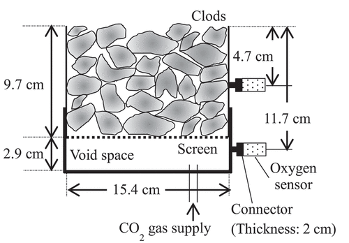
shows a schematic illustration of the experimental apparatus for the gas transfer efficiency measurement; the apparatus was constructed with reference to Scotter and Raats (Citation1968) and Pourbakhtiar et al. (Citation2017).
Figure 1. Schematic of the experimental setup for gas transfer efficiency measurement.
Previous studies on the measurement of the gas diffusion coefficient in porous media applied variable combinations of the purge gas and tracer gas. Although oxygen diffusion into the porous media purged by nitrogen has been the most popular (Osozawa Citation1998), buoyancy or solubility in water was also considered in selecting gases in this study. Scotter and Raats (Citation1968), Pourbakhtiar et al. (Citation2017), and Poulsen et al. (Citation2017) used CO2 as the purge gas and oxygen as the tracer gas because they thought the effects of the buoyancy-driven flow would have occurred if they had used N2 gas for initial purging the experimental columns. Alternatively, Levintal, Dragila, and Weisbrod (Citation2019) used air enriched with 2000 ppm CO2 to fill the experimental columns and monitored the CO2 concentration as the tracer gas because they thought this concentration had no bias due to the buoyancy-driven flow of CO2 as the tracer and CO2 high solubility in the water had no impact as all experiments were conducted under dry conditions. Laemmel et al. (Citation2017) chose helium as the purge and tracer gas because it is an inert gas and its solubility in water is negligible, and the diffusion coefficient in the air is large, while the monitoring of the gas concentration is realized by constructing the elaborate sampling device and the microgas chromatograph. Considering the advantages and difficulties of these methods, this study monitored O2 concentration moving from the air into the soil columns as the tracer gas, and CO2 gas was used for the purge gas to mitigate buoyancy-driven upward mass flow mentioned by Pourbakhtiar et al. (Citation2017). Although CO2 high solubility in soil water should have caused the apparent retardation of CO2 movement, the influence could be canceled by using the relative gas transfer parameters defined in the following sections. A detailed discussion of this issue is provided in Appendix 2.
An empty cap was attached to the lower end of the soil column to create a space for supplying CO2 gas to fill up the soil column. The space had a height of 2.9 cm and was separated from the soil column with a perforated metal board containing 3 mm holes (aperture ratio: 51%). Oxygen sensors (SO-220; Apogee Instruments, USA) were installed at depths of 4.7 and 11.7 cm via the tubes with lengths of 2.0 cm and internal diameters of 0.5 cm. The oxygen sensors were connected to a data logger (CR1000; Campbell Scientific. Inc., USA), which recorded every 1 s. A thermocouple was incorporated into the oxygen sensor, and the oxygen concentration was corrected by the temperature based on the ideal gas law. The sensor’s response time, i.e., when the sensor sensed 90% of the actual gas concentration, was 14 s. In addition to this delay, the distance from the column to the sensor caused a difference in the O2 concentration between the column and the sensor. To estimate this delay, numerical analysis of the O2 diffusion in the connection tubes of the sensors was performed using the numerically obtained solutions for the temporal changes of O2 concentration at 4.7 and 11.7 cm deep as the boundary conditions. The details of this analysis are provided in Appendix 1. As a result, the time until the O2 concentration at the sensor reached the same value as that at the wall of the column almost fell within the range of 13 ± 1.5 s regardless of the elapsed time and the air exchange rate in the columns. Thus, 27 s, i.e., 14 s for the sensors’ response time and 13 s for the diffusion in the connecting tubes, was subtracted from the elapsed time corresponding to each measurement to correct these time lags.
2.3. Procedure for measuring gas transfer efficiency
First, the top of the column was closed with a lid, which contained valves and an oxygen sensor. Subsequently, CO2 gas was injected into the lower space to replace the soil air in the column with CO2 completely. The oxygen concentration in the column was monitored to confirm the replacement. After a complete replacement, the lid was removed to allow the exchange of CO2 and air, and the oxygen concentrations at 4.7 and 11.7 cm deep were continuously measured. The measurements were performed until the output from the oxygen sensors was stabilized for more than 10 min. Then, by assuming that the O2 concentration obtained in the previous 10 min corresponded to that of the atmosphere (i.e., 21%), the output of each sensor was calibrated.
2.4. Environmental conditions during measurements of gas transfer efficiency
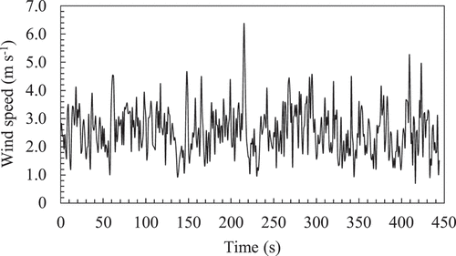
In situ gas transfer efficiency measurements were conducted from June 4 to 14 June 2019, in the clayey rotational paddy field where fairly tilled soil was sampled. The field measured 30 m × 100 m, and the experiments were conducted near the center of the field under soybean cultivation. Double-lined ridges with a height of 24 cm and a top width of 30 cm were formed, but the soybean had not been established to cover the soil surface. The schematic of the in situ measurement is shown in . The soil column was placed on a tray with a bottom size of 38.5 cm × 26.0 cm, which was installed in the ridge by excavating it, and the height of the soil column was equaled to that of the top of the original ridge. Considering the column size and the oxygen sensor length, the dimensions of this tray was suitable for putting the experimental apparatus. This procedure is important for placing the soil column under natural wind conditions in the field. The wind speed () 20 cm above the soil column was measured every 1 s during the measurement by an ultrasonic anemometer (CYG-81000; R. M. Young Company, USA), which was connected to a data logger (CR1000; Campbell Scientific. Inc., USA). An example of the temporal change in
during the measurement is shown in . Each column was measured two or three times under various wind conditions, and seven measurements were conducted for each soil type. Average wind speed (
) and wind speed standard deviation of each measurement is summarized in .
Table 2. Wind speed () during the in-situ measurement (mean ± S.D.)
Figure 2. Schematic of the in situ measurement. (a) Side view (b) Sectional view.
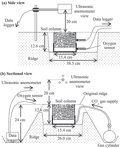
Figure 3. An example of temporal change in wind speed () during the in situ measurement.
After completing the in situ measurements, the samples were subjected to the measurements in the closed laboratory. Because the measured wind speed of 2 m height in the laboratory during 1 hour was only 0.08 ± 0.03 m s−1 (mean ± S. D.), the laboratory was considered to be under calm conditions. The measurements were repeated three times for each soil column.
2.5. Determination of gas transfer efficiency
The gas transfer efficiency in the soil can be simply evaluated based on the time until the oxygen concentration at depths of 4.7 and 11.7 cm reached a certain percentage of that in the atmosphere. Pourbakhtiar et al. (Citation2017) applied the time (‘breakthrough time’) until the oxygen concentration at a given depth reached 50% of that in the atmosphere to analyze the effect of wind on gas movement in the soil. Levintal, Dragila, and Weisbrod (Citation2019) used the time (‘aeration time’) until the CO2 concentration decreased to 10% of the initial one in the column. This study evaluated and
defined as the time until the oxygen concentration at 4.7 and 11.7 cm deep reached 50% and 90% of that in the atmosphere, respectively.
and
corresponded to breakthrough time and aeration time, respectively. The relative gas transfer parameter:
or
, defined as the ratio of
or
in the in situ experiments to that in the laboratory experiment was used to analyze the effect of wind on the gas transfer.
2.6. Determination of molecular diffusion coefficient and apparent gas diffusion coefficient
Based on the study by Ishihara, Shimojima, and Harada (Citation1992), gas movement near a soil surface enhanced by wind can be mathematically described in the form of Fick’s law, as shown in EquationEquation (1)(1)
(1) , regardless of the mechanism of pressure pumping, i.e., via wind-induced pressure fluctuations or aerodynamic dispersion.
where is the gas flux induced by wind (cm s−1),
is the wind-induced gas transfer coefficient (cm2 s−1),
is the gas concentration (cm3 cm−3), and
is the depth (cm). Because molecular diffusion, which is also represented by Fick’s law, is the other driving force of the gas movement, EquationEquation (2)
(2)
(2) governs the temporal change in O2 concentration if the wind-induced gas transfer follows Equation (1):
where denotes the air-filled porosity, and Da is the apparent gas diffusion coefficient or gross gas transfer coefficient (cm2 s−1) defined as
Here, Dm denotes the molecular gas diffusion coefficient (cm2 s−1). should have been a function of depth because the effect of wind turbulence depends on depth, theoretically (Pourbakhtiar et al. Citation2017). However, because the optimal form of
could not be selected explicitly,
was assumed to be constant throughout the soil layer.
To obtain the optimum that reproduces the measured temporal changes in the O2 concentration, EquationEquation (2)
(2)
(2) was solved repeatedly by changing
with the explicit finite difference method. For the laboratory measurement, the following boundary and initial conditions were used to solve EquationEquation (2)
(2)
(2) :
where is the gas flux through the upper boundary of the soil column (cm s−1) and
is the gas transfer coefficient on the upper boundary (cm s−1). However, for the in situ measurement, because the possible decrease in the O2 concentration in the atmosphere due to the downward flux should be compensated readily by wind, the following upper boundary condition was used:
The computational domain was partitioned into an upper soil layer (0–9.7 cm deep), and a lower void space (9.7–12.6 cm deep). The grid interval was set between 0.7 and 1.0 cm, and the time interval
was set to 0.5 or 1 s, considering the stability of the calculation. For the lower void space, the gas diffusion coefficient in air (
), which was measured using an empty column, was applied for the calculation.
The root-mean-square error (RMSE) between the measured and fitted oxygen concentrations at depths of 4.7 and 11.7 cm were used as the criteria, as follows:
where is the number of observations;
and
are the measured and calculated oxygen concentrations at the i-th observation, respectively (cm3 cm−3). The RMSE was evaluated from the onset of measurement until the oxygen concentration at 11.7 cm deep reached 90% of that in the atmosphere.
For the experiments to induce molecular diffusion without soil using the empty column, the optimum and
were simultaneously determined to minimize the RMSE. Then, under the optimum
,
that minimized the RMSE was chosen as the optimum apparent gas diffusion coefficient. Based on the minimum RMSE, the diffusion model applicability was tested for each experimental condition.
To compare the measured with
or
, temperature correction was performed for
and
as follows (Bitteli, Campbell, and Tomei Citation2015):
where ,
, and
are the temperatures (K) during the measurements of
,
, and
, respectively. For the laboratory measurements, the mean temperature between 4.7 and 11.7 cm deep during the measurement was used as
, i.e.,
, and
. For the in situ measurement, the averaged air temperature observed at a weather station located approximately 100 m from the experimental plots was applied as
because the temperatures measured by the oxygen sensors in the columns were probably higher than the actual soil temperature because of direct exposure of sunlight to the oxygen sensors.
2.7. Determination of air permeability
After measuring the gas transfer efficiency, the air permeability was measured under three different gas flow rates using the apparatus shown in . First, N2 gas was injected into the empty cap attached to the lower end of the soil column, and the flow rate of N2 gas was measured using a gas flowmeter (FD-A100; Keyence, Japan). Next, the differential gas pressure between the top and bottom of the soil column was measured using a differential pressure sensor (PDT101; Vaisala Oyj, Finland, for poorly and fairly tilled soil specimens; GC30; Nagano Keiki Co., Ltd., Japan for Mikawa silica sand specimens). Finally, the air permeability was calculated using Darcy’s law, as follows (Hamamoto et al. Citation2009):
Figure 4. Schematic of the experimental setup for air permeability measurement.
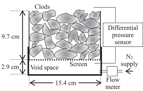
where is the air permeability (cm2),
is the flow rate (cm3 s−1),
is the cross-sectional area of the soil column (cm2),
is the viscosity (=1.82 × 10⁻⁵ Pa s, which is the value at 20°C),
is the height of the soil column (cm), and
is the differential air pressure between the top and bottom of the soil column (Pa). The measured
values are shown in . The
in the poorly and fairly tilled soils were three and two orders higher than that in the Mikawa silica sand, respectively. Notably, because the measurement range of the differential pressure sensor was ±60 Pa and its accuracy was 0.4% span, the measured
(> 0.7 Pa) was within than the sensor’s accuracy.
Table 3. Air permeability of soils (mean ± S.D.)
2.8. Determination of clod size distribution
After performing all measurements, the soil aggregates (clods) in the columns were sieved into six sizes, i.e., 5, 4, 3, 2, and 1 cm openings. The dry weights of each size class were measured to determine the tilth. The clod size distribution can be approximated using the Rosin–Rammler equation as follows:
The mean clod diameter (cm) can be calculated as
where is the opening of the sieve (cm);
is the cumulative weight of clods larger than
(%);
(cm) and
are fitting parameters;
is a gamma function defined as (Takahashi et al. Citation1999)
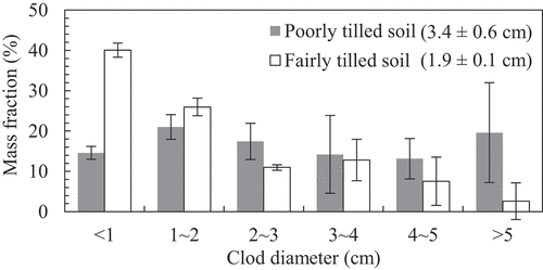
shows the clod diameter distribution and mean clod diameter of the poorly and fairly tilled soils. As expected, the mean clod diameter of the poorly tilled soil was larger than that of the fairly tilled soil.
Figure 5. Clod diameter distribution of the poorly and fairly tilled soil. The error bars represent standard deviations. The mean clod diameter is shown in brackets in the legend (mean ± S.D.).
3. Results and discussion
3.1. Effect of wind on gas transfer efficiency
shows the relationship between the average wind speed () at 20 cm above the soil surface and
or
. In the Mikawa silica sand,
and
was larger than unity at depths of 4.7 and 11.7 cm in almost all cases. Before the onset of the in situ measurement, i.e., when the Mikawa silica sand was packed, the volumetric water content was 0.14 (Section 2.1). However, because of desiccation during the in-situ measurements, the volumetric water content was decreased to 0.06 () at the end of the laboratory measurement. Therefore,
was increased, and a faster gas exchange occurred in the laboratory measurements compared to the in situ measurements, resulting in
and
larger than unity. Additionally, the correlation between
and
or
was not significant. Consequently, the wind speed did not positively affect the gas movement in the Mikawa silica sand. This result is consistent with Fuchs and Hadas (Citation2011), who demonstrated that wind speed did not affect the resistance of 0.2–1 mm aggregates to water vapor transport.
Figure 6. Relationship between and
(the ratio of
at the in-situ experiment to that in the laboratory experiment) at (a) 4.7 and (b) 11.7 cm deep and relationship between
and
(the ratio of
at the in-situ experiment to that in the laboratory experiment) at (c) 4.7 and (d) 11.7 cm deep.
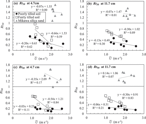
In the fairly tilled soil, both and
were smaller than unity and decreased gradually with the increase in
. Additionally, significant negative relationships were exhibited between
and
at 11.7 cm deep, and between
and
at both depths. Consequently, the gas movement was enhanced by the wind in the fairly tilled soil. Furthermore, the decrease in both
and
with increasing
at 11.7 cm deep was smaller than that at 4.7 cm deep, indicating that the wind effect on gas movement decreased with depth. This result was consistent with that of Pourbakhtiar et al. (Citation2017), who showed that
decreased with depth.
In the poorly tilled soil, and
were significantly decreased even under slight wind. At 4.7 cm deep,
gradually decreased with the increase in
. However,
was no more than 0.3 under the wind speed of 1.2 m s−1 and did not decrease with further increase in
. At 11.7 cm deep, the
and
were also low even under the wind speed of 1.2 m s−1, and not negatively correlated with
. These results indicated that the gas exchange was enhanced by weak wind lower than 1.2 m s−1, but the more increase in the wind speed did not affect the gas exchange in the poorly tilled soil.
Comparison between the fairly and poorly tilled soil on the evaluated and
showed that wind induced the gas movement more in the poorly tilled soil than in the fairly tilled soil under the slow wind speed. However, in the fairly tilled soil, the effect was enhanced with the increase in the wind speed and finally became close to that in the poorly tilled soil at the wind speed around 2.0 m s−1. The difference by the mean clod size is attributable to the air permeability of these soils (), which was indicated by Levintal, Dragila, and Weisbrod (Citation2019). In the poorly tilled soil, the wind effect already reached a plateau under mild wind because the inter-aggregate pores allowed air turbulence propagation and pressure fluctuations. In contrast, in the fairly tilled soil, because the propagation of air turbulence was attenuated more by the resistance of the inter-aggregate pores, the effect probably depended on the amplitude of air turbulence determined by the wind speed.
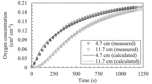
3.2. The molecular gas diffusion coefficient in an empty column
shows the measured temporal change in oxygen concentration at depths of 4.7 and 11.7 cm in the empty column. The molecular gas diffusion coefficient in air () at 20°C and the gas transfer coefficient on the upper boundary (
) was determined to be 0.163 ± 0.003 cm2 s−1 (mean ± S. D.) and 0.084 ± 0.006 cm s−1, respectively. Because the obtained
was similar to 0.16 cm2 s−1 that reported by Marrero and Mason (Citation1972), the obtained
and
were used hereafter.
Figure 7. Temporal change in oxygen concentration measured in the laboratory and its optimum solution obtained using the gas diffusion equation (EquationEquation (2)(2)
(2) ) for the empty column (n = 3). The temporal changes in concentration for all replicates were plotted, while the average of the most optimum numerical solutions for each measurement was shown. Note that the measured data are shown every 30 s.
3.3. The molecular gas diffusion coefficient in soil
shows examples of temporal change in oxygen concentration at 4.7 and 11.7 cm deep measured in a laboratory and the optimized solution of the gas diffusion equation (EquationEquation (2)(2)
(2) ). Because these experiments were performed without wind,
in EquationEquation (2)
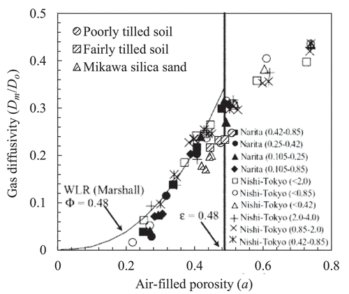
(2)
(2) can be regarded as molecular diffusion coefficient Dm. The Dm values of the poorly tilled soil, fairly tilled soil, and Mikawa silica sand at 20°C were 0.038 ± 0.002, 0.037 ± 0.002, and 0.030 ± 0.002 cm2 s−1, respectively. shows the relationship between air-filled porosity and gas diffusivity (
), obtained in the present study and by Hamamoto et al. (Citation2009), who measured the
of repacked Narita sand and Nishi Tokyo loam with different particle diameters using N2 as the purging gas. Although the bulk density of Mikawa silica sand in our study (1.35 g cm−3) was similar to that of Narita sand in Hamamoto et al. (Citation2009) (1.35–1.37 g cm−3), the gas diffusivity of the Mikawa silica sand in our study was smaller than those of Narita sand, which might be attributed to the apparent retardation by the water solubility of CO2 (Appendix 2).
Figure 8. Examples of temporal change in oxygen concentration measured in the laboratory and its optimum solution obtained using the gas diffusion equation (EquationEquation (2)(2)
(2) ) for (a) poorly tilled soil, (b) fairly tilled soil, and (c) Mikawa silica sand (n = 3). The temporal changes in concentration for all replicates were plotted, while the average of the most optimum numerical solutions for each measurement was shown. Note that the measured data are shown every 60 s.
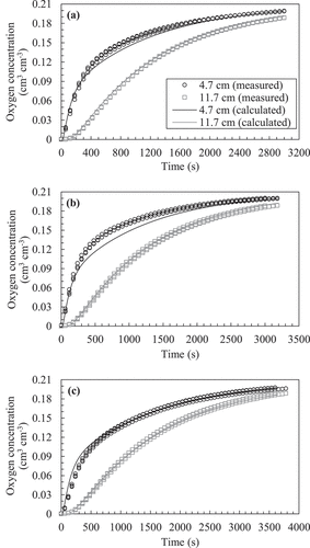
Figure 9. Comparison of gas diffusivity () between our results and that of Hamamoto et al. (Citation2009). This figure is a modified version of presented by Hamamoto et al. (Citation2009), with our results added. They measured the gas diffusivity of ‘Narita’ sand and ‘Nishi-Tokyo’ loam with different particle diameters, indicated in parenthesis in millimeters.
3.4. Applicability of gas diffusion equation to wind-induced gas exchange
) show examples of temporal changes in oxygen concentration and their optimum solutions based on the gas diffusion equation (EquationEquation (2)(2)
(2) ) obtained from in situ measurements for each soil. summarizes the RMSE value of the optimum solutions. In the Mikawa silica sand, because the RMSE was smaller than 0.012 cm3 cm−3 and the shapes of the solution curves were close to the temporal trends in measured oxygen concentration, it could be regarded that the gas diffusion equation successfully reproduced the measured temporal change in oxygen concentration even under wind. However, in the fairly tilled soil, although the RMSE at the wind speed of 1.0 m s−1 was as small as 0.007 cm3 cm−3, it increased gradually with
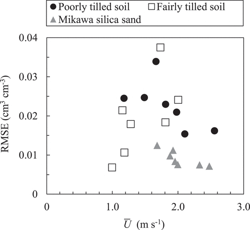
, and the shapes of the solution curves no longer expressed measured trends under the wind speed of 2.0 m s−1 (). In the poorly tilled soil, the RMSE was high regardless of the wind speed. The failure in adopting the diffusion equation to the poorly tilled soil was also obvious from the deviation between the solutions and measured plots at both monitoring locations ().
Figure 10. Examples of temporal change in oxygen concentration measured at the field and its optimum solution obtained using the gas diffusion equation (EquationEquation (2)(2)
(2) ) with the Mikawa silica sand. Note that the measured data are shown every 120 s.
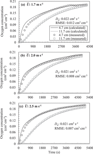
Figure 11. Examples of temporal change in oxygen concentration measured at the field and its optimum solution obtained using the gas diffusion equation (EquationEquation (2)(2)
(2) ) with the fairly tilled soil. Note that the measured data are shown every 60 s.
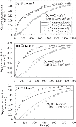
Figure 12. Examples of temporal change in oxygen concentration measured at the field and its optimum solution obtained using the gas diffusion equation (EquationEquation (2)(2)
(2) ) with the poorly tilled soil. Note that the measured data are shown every 30 s.
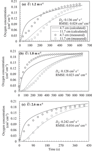
Figure 13. Relationship between average wind speed () and RMSE for each fitting.
Levintal, Dragila, and Weisbrod (Citation2019) demonstrated that, using the gas diffusion (dispersion) equation, the R2 between the measured and calculated temporal changes in gas concentration decreased as the wind speed increased or the air permeability increased. To solve this problem, they added an advection term to the diffusion equation to fit the experimental results. Their modified model successfully reproduced the trends, although they reported uncertainties regarding using the advection-diffusion equation from a physical perspective. Alternatively, in this study, the shapes of the temporal change in the oxygen concentration were different among the experimental runs ()). Considering this feature, a gusty mass flow might occur in the soil column during the in situ measurements, resulting in high RMSE. However, further discussion on the mechanisms cannot be derived from the present experiments.
Although the diffusion model did not accurately reproduce the observed behavior in the tilled soil columns, the relationship between and the relative gas transfer coefficient (
) that minimized the RMSE is shown in as a reference. In the Mikawa silica sand,
was smaller than unity, and no significant relationship was detected between
and
. In the fairly tilled soil,
was larger than unity and increased gradually as
increased. Additionally, a positive relationship between
and
was observed. In the poorly tilled soil,
was larger than that in the fairly tilled soil under all wind speed conditions, and the difference increased with the wind speed, even though the R2 for the correlation between
and
was relatively low in the poorly tilled soil.
Figure 14. Relationship between average wind speed () and the ratio of the apparent gas diffusion coefficient (
) to the molecular gas diffusion coefficient (
).
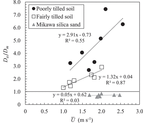
As shown above, the diffusion/dispersion equation hardly reproduces the gas movement through the soil layer with large clods under the moderate wind. Thus, the wind-induced gas transfer should be primarily quantified by the parameters that do not assume any models. However, rough estimates of the gas movement through the poorly fragmented soil layer are necessary for practical purposes in agriculture or environmental sciences. shown in is considered useful to understand the range of the effect of wind on gas transfer in poorly fragmented soil that is often found in paddy fields.
4. Conclusion
This study quantified the effect of wind on gas transport in the clayey paddy soil layer comprised large clods based on in situ and laboratory experiments. Gas transfer through the paddy soil layers, composed of a few centimeters of clods, under natural wind was up to eleven times as quick as under calm conditions. The wind-induced gas exchange remained at maximum at a wind speed of more than 1.2 m s−1 at 20 cm above the soil surface, with a mean clod size of 3.4 cm. In contrast, in the soil layer with a mean clod size of 1.9 cm, the effect of wind on gas exchange gradually increased with wind speed and finally became close to that in the poorly tilled soil at a wind speed around 2.0 m s−1. The applicability of the gas diffusion equation deteriorated when the mean clod size changed from 1.9 to 3.4 cm, or the wind speed increased from 1.2 to 2.6 m s−1. From these findings, the effect of wind should be considered in the analysis of the in situ gas exchange in paddy soil with large aggregates having a mean size larger than 2 cm. In such cases, we should note that the diffusion/dispersion equation cannot reproduce the behavior accurately.
Acknowledgments
We are grateful to the field management staff at the National Agricultural Research Center (NARO) for their experimental assistance and technical advice, Dr Katsuhiro Suzuki at NARO for providing us with the experimental field, and Dr Tatsuo Hosono at NARO for providing us with the meteorological data.
Disclosure statement
No potential conflict of interest was reported by the author(s).
Additional information
Funding
References
- Bitteli, M., G. S. Campbell, and F. Tomei. 2015. Soil Physics with Python: Transport in the Soil-plant-atmosphere System. New York: Oxford University Press.
- Clements, W. E., and M. H. Wilkening. 1974. “Atmospheric Pressure Effects on 222Rn Transport across the Earth-air Interface.” Journal of Geophysical Research 79 (33): 5025–5029. doi:https://doi.org/10.1029/JC079i033p05025.
- Farrell, D. A., E. L. Greacen, and C. G. Gurr. 1966. “Vapor Transfer in Soil Due to Air Turbulence.” Soil Science 102 (5): 305–313. doi:https://doi.org/10.1097/00010694-196611000-00005.
- Fuchs, M., and A. Hadas. 2011. “Mulch Resistance to Water Vapor Transport.” Agricultural Water Management 98 (6): 990–998. doi:https://doi.org/10.1016/j.agwat.2011.01.008.
- Fujikawa, T., and T. Miyazaki. 2005. “Effect of Bulk Density and Soil Type on the Gas Diffusion Coefficient in Repacked and Undisturbed Soils.” Soil Science 170 (11): 892–901. doi:https://doi.org/10.1097/01.ss.0000196771.53574.79.
- Fukuda, H. 1955. “Air and Vapor Movement in Soil Due to Wind Gustiness.” Soil Science 79 (4): 249–256. doi:https://doi.org/10.1097/00010694-195504000-00002.
- Hamamoto, S., P. Moldrup, K. Kawamoto, T. Komatsu, and D. E. Rolston. 2009. “Unified Measurement System for the Gas Dispersion Coefficient, Air Permeability, and Gas Diffusion Coefficient in Variably Saturated Soil.” Soil Science Society of America Journal 73 (6): 1921–1930. doi:https://doi.org/10.2136/sssaj2009.0012.
- Hillel, D. 1998. Environmental Soil Physics. San Diego: Academic Press.
- Ishihara, Y., E. Shimojima, and H. Harada. 1992. “Water Vapor Transfer beneath Bare Soil Where Evaporation Is Influenced by a Turbulent Surface Wind.” Journal of Hydrology 131 (1–4): 63–104. doi:https://doi.org/10.1016/0022-1694(92)90213-F.
- Kimball, B. A., and E. R. Lemon. 1971. “Air Turbulence Effects upon Soil Gas Exchange.” Soil Science Society of America Proceedings, 35, 16–21.
- Laemmel, T., M. Maier, H. Schack-Kirchner, and F. Lang. 2017. “An in Situ Method for Real-time Measurement of Gas Transport in Soil.” European Journal of Soil Science 68 (2): 156–166. doi:https://doi.org/10.1111/ejss.12412.
- Laemmel, T., M. Mohr, B. Longdoz, H. Schack-Kirchner, F. Lang, D. Schindler, and M. Maier. 2019. “From above the Forest into the Soil – How Wind Affects Soil Gas Transport through Air Pressure Fluctuations.” Agricultural and Forest Meteorology 265: 424–434. doi:https://doi.org/10.1016/j.agrformet.2018.11.007.
- Levintal, E., M. I. Dragila, and N. Weisbrod. 2019. “Impact of Wind Speed and Soil Permeability on Aeration Time in the Upper Vadose Zone.” Agricultural and Forest Meteorology 269–270: 294–304. doi:https://doi.org/10.1016/j.agrformet.2019.02.009.
- Marrero, T. R., and E. A. Mason. 1972. “Gaseous Diffusion Coefficients.” Journal of Physical and Chemical Reference Data 1 (1): 3–118. doi:https://doi.org/10.1063/1.3253094.
- Osozawa, S. 1998. “A Simple Method for Determining the Gas Diffusion Coefficient in Soils and Its Application to Soil Diagnosis and Analysis of Gas Movement in Soil (In Japanese with English Summary).” Bulletin of National Institute for Agro-Environmental Sciences 15: 1–66.
- Poulsen, T. G., A. Pourber, A. Furman, and K. Papadikis. 2017. “Relating Wind-induced Gas Exchange to Near-surface Wind Speed Characteristics in Porous Media.” Vadose Zone Journal 16 (8): 1–13. doi:https://doi.org/10.2136/vzj2017.02.0039.
- Pourbakhtiar, A., T. G. Poulsen, S. Wilkinson, and J. W. Bridge. 2017. “Effect of Wind Turbulence on Gas Transport in Porous Media: Experimental Method and Preliminary Results.” European Journal of Soil Science 68 (1): 48–56. doi:https://doi.org/10.1111/ejss.12403.
- Sato, T., Y. Kaneta, N. Furuta, H. Kobayashi, H. Shindo, T. Ota, and A. Sato. 2003. “Effect of Soil Physical Properties on Soybean Nodulation and N2 Fixation at the Early Growth Stage in Heavy Soil Field in Hachirougata Polder, Japan.” Soil Science and Plant Nutrition 49 (5): 695–702. doi:https://doi.org/10.1080/00380768.2003.10410327.
- Scotter, D. R., and P. A. C. Raats. 1968. “Dispersion in Porous Mediums Due to Oscillating Flow.” Water Resources Research 4 (6): 1201–1206. doi:https://doi.org/10.1029/WR004i006p01201.
- Scotter, D. R., and P. A. C. Raats. 1969. “Dispersion of Water Vapor in Soil Due to Air Turbulence.” Soil Science 108 (3): 170–176. doi:https://doi.org/10.1097/00010694-196909000-00004.
- Stępniewski, W., Z. Stępniewska, and A. Rożej. 2011. “Gas Exchange in Soils.” In Soil Management: Building a Stable Base for Agriculture, edited by J. L. Hatfield and T. J. Sauer, 117–144. Madison: ASA, CSSA, and SSSA Books.
- Takahashi, T., C. Y. Park, H. Nakajima, H. Sekiya, and K. Toriyama. 1999. “Ferric Iron Transformation in Soils with Rotation of Irrigated Rice-upland Crops and Effect on Soil Tillage Properties.” Soil Science and Plant Nutrition 45 (1): 163–173. doi:https://doi.org/10.1080/00380768.1999.10409332.
Appendix 1:
Estimation of the range of the error and time lag of the measured O2 concentration caused by the distance from the column to the sensors
The expected time lag due to the distance between the column and the sensor probe was analyzed based on the numerical solution of the diffusion equation. Because the tubes having an inner diameter of 0.5 cm and the length of 2 cm to connect the inner wall of the column and sensors allowed free interdiffusion of CO2 and air, the O2 concentration () within the connecting tube follows:
where is the distance from the column (cm),
is distance from the column to the O2 sensor probe (=2 cm), and
denotes the temporal O2 concentration in the column at the depth of the O2 sensor (cm3 cm−3). Generally,
is also influenced by the diffusion to the sensor. However, we ignored it because the horizontal diffusion into the sensors were small compared to the vertical diffusion in the column.
was calculated by solving the boundary problem described by Equationequations (2)
(2)
(2) , (Equation5
(5)
(5) ), (Equation6
(6)
(6) ), and (Equation7
(7)
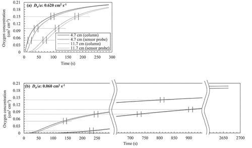
(7) ). To estimate the time lags between the O2 concentration in the column and the measured ones by the sensors,
ranging from 0.060 to 0.620 cm2 s−1 was applied for calculating
. Note that the obtained
in this study was within this range. shows the evaluated difference in O2 concentration in the column and at the sensor probe for the cases assuming
, as examples. Although the maximum difference in the concentration was expected in the rapid increasing stage and cases, the time lags almost fell within 13 ± 1.5 s regardless of the elapsed time and
in the column.
Figure A1. Comparison between the oxygen concentration in the column and at the sensors after the numerical simulation. (a) (b)
. The time lags are represented by the distance between the short vertical bars.
Appendix 2:
On the influence of dissolution of CO2 in the soil moisture
Because the solubilityof carbon dioxide in water is so high, the injected CO2 gas probably dissolved to the moisture in the soil aggregates. Assuming the concentration of CO2 in the gas and liquid phases is in equilibrium following Henry's law, the volumetric concentration of CO2 in both phases can be simply modeled as:
where is the CO2 concentration in the gas phase (cm3 cm−3),
is the CO2 concentration in the liquid phase (cm3 cm−3), and
is the Henry’s coefficient (=1.14 after Fujikawa and Miyazaki Citation2005). If the gas movement in the soil can be represented by the diffusion equation, the CO2 concentration obeys the following equation:
where is the volumetric water content. Substituting Equation (A5) into Equation (A6) yields..
Because the sum of the concentration of CO2 and air is one and the proportion of oxygen in the atmosphere is constant, (A7) can be also represented as..
where is the oxygen concentration in the gas phase (cm3 cm−3).
By comparing with EquationEquation (2)(2)
(2) , Equation (A8) shows that the elution of CO2 from the soil aggregates delays O2 exchange by a factor of
, which does not depend on
. The factor
ranges from 0.63 to 0.68, 0.68 to 0.73, and 0.78 to 0.89 for the poorly tilled soil, fairly tilled soil, and Mikawa silica sand, respectively. These values were calculated from the actual water content and air-filled porosity in the columns provided as . Therefore, although the effect of dissolution of CO2 cannot be ignored in the estimation of the diffusion coefficient itself, the relative diffusion coefficient
or the relative gas transfer parameters
and
are not affected by the dissolution of CO2.