
ABSTRACT
The Tsumeb Mine in Namibia represents one of the best-preserved mining sites in the world and is rapidly gaining cross-disciplinary interest among cultural and engineering scientists. Most of the open pit and the shaft mining equipment are still in place, including the ore processing units and the local power plant. The mining area thus deserves recognition as an industrial world heritage site, especially due to the rarity of such locations on the African continent. The Shaft #1 headgear, built in 1924, represents one of the oldest known riveted steel headgears of the Promnitz design worldwide. In contrast to similar steel structures located in the northern hemisphere, it has been exposed to a different rural semi-arid climate since it is located in the Otavi Mountain Land, characterized by semi-annual change of rainy and dry seasons. Parts of the Shaft #1 headgear have remained largely untouched for more than 70 years. Besides its outstanding heritage value, it thus also represents an interesting object for studying the composition of corrosion layers formed on mild steel surfaces when exposed to continental and industrial mining atmospheres. To find a suitable transparent corrosion prevention coating, various on-site coating samples were evaluated after 11 months of outdoor exposure, including Owatrol Oil®, which is based on natural oil and alkyd resin with strong wicking potential. The substance is frequently applied for the conservation of single components but is not yet widely used on large steel structures in the field of industrial heritage conservation. However, it represented the most stable anti-corrosion coating under the local atmospheric conditions in the on-site tests. Thus, the suitability of Owatrol Oil® as a transparent coating for corrosion protection of riveted mild steel structures in such climates was further investigated as a more recent approach for the conservation of large steel structures. Since the protective coatings are exposed to strong UV radiation in the local climate, the addition of a specific UV stabilizer mixture was also tested. For such laboratory tests, two mild steel samples were taken. The first one originated from a diagonal strut of the 1920s and the second one from a handrail mounted in the early 1960s. Using corresponding high-resolution scanning electron microscopy (HR-SEM) and energy-dispersive X-ray spectroscopy (EDX) it was found that the corrosion layers are predominantly composed of lepidocrocite and goethite. A weathering program simulating the specific environmental conditions at Tsumeb in a UV climate chamber was developed and the corrosion resistance of the mild steel surface was subsequently evaluated by potentiodynamic measurements. Such tests proved to be a fast and reliable procedure for ranking the corrosion resistance of the old mild steels. It was found that the long-term corrosion layers already provide significant protection against further corrosion in the simulated environment. However, the study also showed that this can be further improved by the application of the Owatrol Oil® as a protective coating that also seals crevices. The addition of the UV stabilizers, however, led to a significant deterioration in corrosion protection, even in comparison to that of the uncoated long-term corrosion layers on the surface. Regular overcoating seems more advisable for the long-term preservation of the Shaft #1 headgear than modifying the Owatrol Oil® coating with the tested UV-stabilizing additives.
Introduction
Relevance
The Tsumeb Mine, located in the Otavi Mountain Land in Namibia, has been referred to as a superlative mine (Fait Citation2017, Citation2019). This is likely due to an ore body revealing an exceptional production rate of highly concentrated lead, copper, and zinc ores. The mine is also unique regarding the presence of unusual minerals (like germanite), its extreme diversity of minerals, and the shafts that are nearly 1700-m deep, which were among the deepest for their time (Schnorbus Citation2000; Scholz and Frautschy Citation2019/Citation2020; Soehnge Citation1967). For these reasons, and because it represents one of the best-preserved mining sites in the world, the area deserves recognition as an industrial world heritage site. Transformed into an open-air museum, the site would enable residents, visitors, and scientists alike to vividly experience Namibia’s mining history and geology as well as the development of mining technology. This also opens up new economic prospects for the local population. The Shaft #1 (Friedrich-Wilhelm) headgear is one of the most prominent landmarks of the mine and the town of Tsumeb, Namibia, together with the DeWet headgear which was built later ().
Figure 1. Shaft #1 headgear. Upper: Relevant objects for development of the Tsumeb mining site as a national heritage site (Scholz and Frautschy Citation2019, Citation2020). 1, new (Friedrich-Wilhelm) Shaft #1 headgear; 2, DeWet Shaft headgear; 3, main ore conveyer; 4, power plant hall; and 5, mineralogy building. Lower: left, photograph of the old (left) headgear from 1908 and the new (right) Shaft #1 headgear from 1925 (Scholz and Frautschy Citation2019, Citation2020; Jassmann Citation2020); right, Engineering illustration of the new Shaft #1 headgear (Jassmann Citation2020).
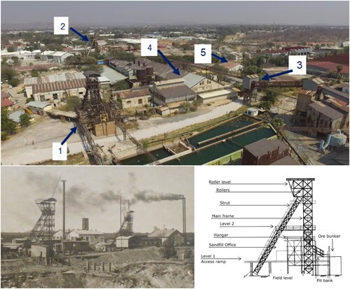
Designed and mounted between 1922 and 1924, the Shaft #1 headgear represents one of the oldest riveted steel mining headgears of the Promnitz design (Fait Citation2017; Jassmann Citation2020). This type of headgear was developed as early as 1874. Earlier steel headframes suffered frequently from fatigue fracture caused by rapid load changes and thus could only gradually replace the older wooden or stone-walled structures in the mining industry. As a pioneer of steel headgears, Promnitz continuously improved his design by application of respectively innovative and much more fatigue-resistant steels developed over the decades. The Promnitz steel headgear, also named German strut framework, does not have additional upright supports as typically seen in previous designs (Schönberg Citation1997). The main framework carries the vertical loads and is connected to the struts via girders that also carry the main loads of the cable sheaves ( lower right). Further advantages of this headframe type include easy adaptability to the local environment as well as much improved shipping requirements and the simplicity of on-site assembly eliminating the requirement for trained staff being present. When these features are considered alongside its extended lifespan of up to 50 years, Promnitz headgears developed into a global export hit (Fait Citation2017, Citation2019). The Shaft #1 headgear in Tsumeb, Namibia represents probably the last existing system on the African continent.
History
The Tsumeb ore body had been known for centuries before industrialization began in the early 1900s. For countless centuries, copper ores were hoisted from deposits in the Otavi Mountain Land, especially from the 12 m high green hill at Tsumeb, by the Hai||om (San People) who were interculturally related by marriage to the ǂNū-khoen (Damara People). It is not totally clear if the Damara people were also ancient metallurgists and introduced the copper-smelting techniques into these regions or if they learned or copied these from the Ovambo People who migrated into the region about 200 years ago. However, it is known that the San and Damara People, respectively, traded copper ores with the Ovambo People who were copper smiths and produced artefacts, particularly jewelry and weapon accessories such as arrow and spear tips, which they traded both back to their ore source tribes and along to other tribes. It also appears very likely that the ancient copper-smelting techniques were traded into the Otavi Mountain Land from more north-eastern regions of the Katanga Copperbelt located in today’s Democratic Republic of Congo (DRC) and Zambia (Nujoma Citation2009). Obviously, the San and Damara People were able to keep the exact local origin of their wealth a secret for several centuries. Europeans did not take notice of the intense copper and ore trading in the Tsumeb region until the mid-nineteenth century (Soehnge Citation1967; Vedder Citation1938).
In contrast to the ancient metallurgy in the Otavi Mountain Land, the industrial development of the Tsumeb mine is quite well documented (Schnorbus Citation2000; Soehnge Citation1967). It was initiated by the expedition of Matthew Rogers who was in charge of investigating the ore deposits of the Otavi Mountain Land for the South West Africa Company (SWAC) in 1892 and, especially, by the further exploration of the Tsumeb ore deposit by Christopher James for the Otavi Minen und Eisenbahngesellschaft (OMEG) in 1900/01. Extraction of the ores and their concentrates was supplied by a narrow-gauge railway to the coast over a distance of 560 km. Before it was shut down in 1998, the mine was rebuilt numerous times and the facilities for extracting and processing of the ores were frequently modernized.
When the Tsumeb mine restarted operation after WWI under the South African Protectorate in 1922, a new shaft was drilled which was then named Shaft #1 and a new headgear was ordered from the Gossen company in Berlin. In 1923 parts were prefabricated in Germany, boxed in wooden containers, shipped to Swakopmund, and transported to Tsumeb by narrow-gauge railway. The headgear mounted above the new Shaft #1 in 1924 was not the first one of this type in Tsumeb ( lower left). In 1908, a similar headgear was built above the former Shaft #1 and was located right at the margins of the open pit. This headgear does not exist anymore, but old photographs document that it had also been a Promnitz design with the above-mentioned advantages ( lower right).
After starting operation in early 1925, the Shaft #1 and headgear was renamed Friedrich-Wilhelm Shaft in recognition of the South African general manager of the mine at this time, Friedrich-Wilhelm Kegel. The first Shaft # 1 head tower ( lower left) was demounted in 1926 and it had then been re-erected at the Abenab mine after WWII (Scholz and Frautschy Citation2019/Citation2020).
The current study focused on two subjects. Firstly, the long-term corrosion behavior in the semi-arid local climate was evaluated, examining two steel specimens taken from different parts of the headgear, exposed over 95 and about 60 years, respectively. Secondly, on-site weathering tests for identification of an appropriate transparent conservation coating revealed inadequate stability of microcrystalline waxes in the prevailing climate. In contrast, application of a product based on resinifing natural oil and alkyd resin that also has a strong wicking potential, i.e. Owatrol Oil®, exhibited no changes of the coated surfaces, even after 11 months. For the first time, the conservation and corrosion protection applicability of Owatrol Oil® at large steel structures exposed to semi-arid African climates has thus been evaluated. For this, a short-term test procedure was developed that can generally be used in any future laboratory studies to evaluate and compare the corrosion protection and conservation potential of various coatings on corroded steel structures and components in the field of industrial heritage.
Condition assessment
The Shaft #1 headgear has been exposed for more than 95 years to a special climate. Unlike most mining towers of this design type located in the northern hemisphere, this headgear has been exposed to a climate with only one rainy and one dry season per year and at higher average temperatures (Jassmann Citation2020).
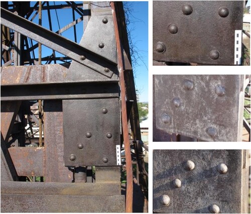
Depending on the location and exposure, different states of preservation were determined (). The upper levels of the headgear ( upper left) are in good condition with remains of the original coating on a large area ( upper right and lower). It is anticipated that the surface of the original steel parts was either protected by oil-flaming or by tar-coating. Both practices were common during the first quarter of the twentieth century.
Figure 2. Corrosion phenomena on the steel surface at various regions of the headgear. Upper left: Shaft #1 headgear, overview. Upper right: gusset plate at center main column of Level 2 (south). Lower left: shallow pitting corrosion at a handrail. Lower center: main column at Level 2 (east side) with coating remains. Lower right: ore dust accumulation at the lower column parts.
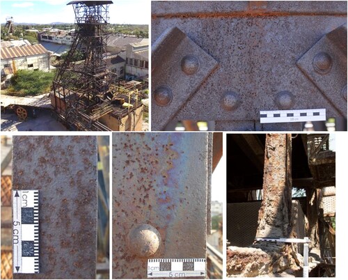
The upper levels are subjected to direct sunlight for several hours a day and almost constant wind. After rain, which normally only occurs between October and March, the steel structure dries off quickly. During the rest of the year, the relative humidity ranges only between 10% and 40% at average temperatures above 22°C. Little corrosion occurs under these conditions, because the steel is, if at all, only barely covered by condensates during the day-and-night cycles. Thus, corrosion reactions only occur in the short phases in which sufficient electrolyte is present. Due to the partly perforated original coating, the corrosion phenomena on the surface are not uniform and can best be described as very shallow pitting corrosion. This is not regarded as harmful, because there was not any significant reduction of cross-sections. However, at riveted overlaps at gusset plates and struts ( upper right and lower center), differently colored corrosion products indicate a slightly more severe attack that likely occurs inside respective crevices at such overlap joints. This was particularly observed where rainwater accumulated due to gravity and drying in respective crevices had been retarded.
The lower levels of the headgear are in significantly worse condition. A reason for this is the microclimate in combination with the coverage of the steel parts with blown debris composed of sand and ore dust. On the lower levels, many spots are not reached by wind and sunlight. Several centimeter-thick ore dust deposits have been observed that are also clogging the drainage of the construction ( lower right). The ores hoisted at the Shaft #1 at Tsumeb were extremely rich in copper, zinc, and lead. The tough ore dust/sand coverage of the steel not only retains moisture, but also has a high content of metals much more noble than the low-carbon steel underneath. It represents a well-known fact that aqueous electrolytes in such crevices are extremely acidic, due to pH, oxygen, and potential depletion. Due to the more noble metal contents of the ore dust/sand coverage, corrosion of the steel surface inside such crevices is additionally enhanced by galvanic effects that cause anodization and metal dissolution at the steel surface. Associated with the higher corrosion rates, extensive metal dissolution has been observed at such parts. Especially at these locations of the structure, removal of the sand/ore dust coverage and application of a protective coating is essential to prevent further corrosion.
Experimental
A preliminary onsite test series was carried out over a period of 11 months investigating the stability of various transparent substances with the goal to select a coating that preserves the authentically aged appearance of the Shaft #1 headgear. These sample coatings were applied to locations of the headgear that are directly exposed to weathering conditions with multiple daily wet and dry cycles. The cleaning before coating was carried out using soft wire brushes, rinsing with water, and subsequent drying over a day.
The sample areas were coated for comparison using a mixture of microcrystalline waxes of the Tecero® series and by Owatrol Oil®. Transparent protective coatings for large-scale iron and steel monuments in central European climates have been extensively studied, for instance by Brüggerhoff et al. (Mazzon, Letardi, and Brüggerhoff Citation2021). Owatrol Oil® has been shown to be particularly effective on corroded substrates. Based on these studies, Owatrol Oil® was preferentially considered in the present study to investigate its applicability for conservation of large steel structures exposed to quite different semi-arid continental climates. With respect to long-term conservation, it must be considered that the coating is exposed to about six times higher ultraviolet (UV) radiation than in the northern hemisphere, such as in North America or Europe. To increase the UV stability of Owatrol Oil®, UV stabilizers that are normally used for clear coats in the automotive industry were added. Tinuvin 292®, a hindered amin type radical quencher (hindered amin light stabilizers HALS) and 900, a UV absorber, were added at 0.5% and 1% according to the recommended concentrations in the product data sheet. The combination of radical quencher and absorber is recommended by the manufacturer for outdoor applications and can significantly extend the protective effect of a coating (Valet Citation1996).
Subsequent to the on-site studies, two representative mild steel samples were taken from the Tsumeb Shaft #1 headframe and were subjected to laboratory tests. The specimens originate from the locations as shown in and have the dimensions shown. The angular profile represents a part of the original steel frame structure erected in 1925. It is assumed to be flame cut from the location shown in (upper left) at a time when one of the two cable sheaves was replaced, and it was salvaged from a location on the Level 2 platform directly underneath. This specimen was taken to compare the long-term corrosion products formed on the surface for about 35 years longer than those on the second specimen.
Figure 3. Locations of the specimens taken from the Shaft #1 headgear. Upper left: location of the angular profile. Upper right: location of the flat profile. Lower left: dimensions of the angular profile 60 × 60 × 5 mm. Lower right: dimensions of the flat profile 40 × 8 mm.
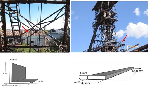
The flat profile was saw-cut out of the railing at the first working level of the original structure. According to documents of the Shaft #1 headframe, this level was built around 1960 when ore transportation during mining was changed from wagons to buckets ( upper right).
The corrosion layers were investigated by HR-SEM on the flat surfaces of the samples. Additionally, cross-sections from both specimens were taken for optical microscopy of the microstructure and EDX mapping of the corrosion layers, as well as for determination of the chemical composition by spark emission spectroscopy.
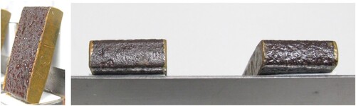
The flat profile already used to determine corrosion products provided sufficient material to investigate in detail the effectiveness of the corrosion protection oil selected based on the preliminary on-site study and intended to be used for conservation of the complete steel frame structure. One particular goal of this investigation was to elucidate the effects of added UV blockers to the coating on its corrosion prevention potential. For the study, the profile was cut into 20 mm wide coupons (). The freshly cut bare metal edges were coated with a masking varnish developed for electroplating (Wideland, Citationn.d.). The corroded surfaces were coated with a single layer of roughly the same amount of Owatrol Oil® with and without UV stabilizers using a brush. The thickness of the dried coating, however, could not be accurately measured, due to the non-magnetic corrosion layers.
Figure 4. Test coupons after climate chamber testing. Left: test coupon with alkyd resin-based coating at 201 h exposure. Right: coated with alkyd resin-based substance with UV-blocker addition (left) and without (right) – all specimens coated with the UV blocking additive lost luster in the coating after the climate test chamber exposure.
All coupons were then subjected to a climate chamber test. Since there was only a short time available for tests before the on-site conservation treatment had to begin, the artificial weathering had to be limited to two weeks. In order to achieve the highest possible UV exposure, the samples were irradiated continuously over the entire period with a UV light source with a wavelength of 340 nm and 40 W/m², which can be regarded as a worst-case scenario ().
Table 1. Test series for climate chamber exposure and for subsequent potentioscans, all samples were saw-cut and fresh metal edges were coated with a masking varnish.
The maximum and minimum values for humidity and temperature were taken from the climate recordings of Tsumeb over the course of a year and a corresponding short-term weathering program was developed. Temperature and humidity were alternated every four hours to simulate the local day and night cycles. Different seasonal temperature fluctuations were simulated every eight hours, in order to expose the samples to mechanical stresses that were as realistic as possible. In addition to the seasonal fluctuations in humidity, the samples were sprayed with an electrolyte every two days to simulate precipitation. To stay conservative in the tests under short-term exposure, a more aggressive test solution was selected than what would be expected in the actual mild industrial environment at Tsumeb. This electrolyte consisted of 8.4 g of NaHCO3, 2.5 ml of 40% NaHSO3 solution and 160 mg NaCl per liter of demineralized water to simulate possible exposure to acid rain. Each test series comprised eight samples: four were weathered and four were non-weathered. Two of the original specimens and two of the coated specimens, respectively, two of the non-weathered and two of the weathered ones were subjected to potentiodynamic polarization tests by submerging them into above-mentioned test solution at a sweep rate of 2 mV/s (). The recorded characteristic potentials and the current density-potential curves allow conclusions about the protective effect of the various coatings with and without UV-blocker addition. An increase in the current density indicates a current flow through the coating, indicating a lower protective effect. As shown by Saha (Saha Citation2013), this method has proven to be suitable elsewhere for evaluating weathered mild steels with regard to their corrosion resistance.
Results and discussion
Outdoor weathering and selection of protective coating
When selecting a protective coating for preservation measures of large structures in the field of industrial heritage conservation, application aspects have to be taken into account with regard to the environmental conditions in the specific climate. Also, removing aged coatings with solvents is not feasible in many cases, due to the extensive and porously corroded surfaces. For long-term preservation, the durability of the coating and its ability to be painted over often turn out to be more relevant than its reversibility.
For the Shaft #1 headgear in Tsumeb, Namibia, it was thus decided early on to preserve the naturally aged appearance of the corroded steels in order to keep the design as well as the aging phases of the structure recognizable. From a processing point of view at large steel structures, the coating must be suitable for spraying application. Brush application would be too ineffective for the headgear’s total surface area of 800 m2. As all this is not achievable with modern colored topcoats, only transparent coatings were considered.
The on-site weathering exposure tests of several microcrystalline waxes showed changes in appearance after only a few months (). Interestingly, the formerly semi-gloss surface became increasingly white with increasing exposure time. Microcrystalline waxes consist of a mixture of n- and iso-alkanes (unbranched and branched paraffin) and naphthenic hydrocarbons (cycloparaffin) (Koller and Baumer Citation2000). The short-chain wax components, which add flexibility to the coating, sublimate more quickly due to their low molecular weight. As a result, the higher molecular weight hydrocarbons accumulate in the coating, causing it to become brittle (Koller and Baumer Citation2000). This effect was probably accelerated by the relatively high surface temperatures on the headgear, where up to 70°C was measured.
Figure 5. Samples of Tecero® Wax coating. The right images show the condition on May 2018 (top), November 2018 (middle), and October 2019 (below), respectively.
Some transparent oil-based substances also turned out not to be suitable for application on the headgear. Due to their higher viscosity, they could only be applied using a brush and showed only marginal creeping effects, which are essential to prevent or stop localized corrosion in crevices, especially underneath the rivet heads on the structure. In contrast, Owatrol Oil® exhibited a much lower viscosity and could thus be more easily applied on the surfaces. It also showed a significantly higher degree of gloss than the waxed surface. The Owatrol Oil® treated surfaces exhibited no visible changes after 11 months of exposure. However, during application it became clear that the addition of the UV stabilizers increased the viscosity thus decreasing the penetration capacity of the dissolved Owatrol Oil®. It must be emphasized that the excellent penetration found previously (Mazzon, Letardi, and Brüggerhoff Citation2021) is crucial for the good protective properties of Owatrol Oil® on corroded substrates. This particularly applies to prevention of localized corrosion on large steel structures where crevices under the conditions of atmospheric corrosion of mild steels might represent unprotected anodic sites of metal dissolution. The corrosion rate might be highly accelerated if large cathodic surface areas are established in the vicinity by covering the surrounding mild steel surface with long-term corrosion prevention products. In the case of the studied headgear, this is particularly the case under rivets and overlapping gusset plates where, according to the mechanisms of localized corrosion, first oxygen access and, in later stages, water access needs to be prevented.
Metallurgy of the steel samples
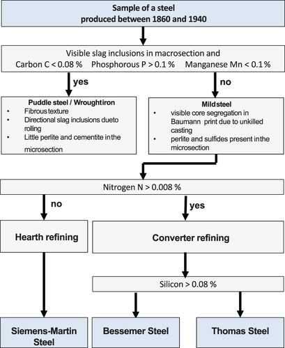
The chemical compositions of the two steels are listed in . The angular profile steel has a C content above 0.08 wt.%, a Mn content above 0.1 wt.% and a P content below 0.1 wt.% which classifies it as typical mild steel (Langenberg Citation1995). The angular profile steel exhibits a (N) content significantly below 0.008 wt.% and thus represents a typical Siemens-Martin steel. The chemical composition of the angular profile shows that high-quality steels were selected for the Shaft #1 headframe. This is remarkable, considering the situation in the early 1920s after WWI when only ca. 50% of the steels were produced in Germany by such modern technologies.
Table 2. Chemical composition (wt.%) of the investigated mild steel specimens (elements of major importance are printed in bold letters), measured by emission spark spectroscopy.
The flat profile steel also has an Mn content above 0.1 wt.% and a P content below 0.1 wt.%. Although it has a considerably low C content that normally characterizes a puddle steel, it has to be classified as a low-carbon fine-grained structural steel since it was produced in the 1960s. With a (N) content above 0.008 wt.% and a Si content significant below 0.08 wt.%, the flat profile material is classified as a typical Thomas steel ().
Figure 6. Flowchart for the classification of old steels as puddle or mild steels according to Langenberg (Langenberg Citation1995).
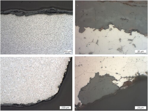
The microstructure of both steel profiles can be seen in . At lower magnification, both steels show typical sulfide lines ( upper and lower left). Obviously, the higher Mn content in both steels accomplished sufficient binding of S to MnS which might also be the reason that both profiles did not exhibit any pronounced core segregations. In the close-ups ( upper and lower right) both steels exhibit some small pearlite islands, which can readily be identified by their laminar structure.
Figure 7. Microstructure of the two steel profiles investigated with scanning electron microscopy (SEM). Upper left: flat profile – cross-section in rolling direction with corrosion layer, low magnification. Upper right: flat profile – cross-section in rolling direction with corrosion layer, high magnification. Lower left: angular profile – cross-section perpendicular to rolling direction with corrosion layer, low magnification. Lower right: angular profile – cross-section perpendicular to rolling direction with corrosion layer, high magnification.
Corrosion products
Structures and components of todaýs industrial heritage sites have mostly been manufactured from mild and/or weathering steels that are predominantly subjected to atmospheric corrosion. A closer look in the literature (Inouye, Ishii, and Kaneko Citation1972; Misawa, Hashimoto, and Shimodaira Citation1974; Evans Citation1992; Balasubramanian et al. Citation1999; Yamashita et al. Citation2001; Morcillo et al. Citation2011; Montoya et al. Citation2013; Morcillo et al. Citation2013; Saha Citation2013; Antunes et al. Citation2014; Rohberge Citation2018) shows that there is not yet a fully consistent understanding regarding the long-term formation and transformation of corrosion products on such low alloyed mild and weathering steel surfaces. However, some general statements can be drawn from the literature with respect to the long-term exposure of the investigated Shaft #1 headframe in the semi-arid continental environment in Northern Namibia, which is characterized by long wet-dry cycles in the rainy season and several months of totally dry periods:
As time progresses in such predominantly dry atmospheres, the less stable oxyhydroxide lepidocrocite γ-FeOOH can transform into the more stable oxyhydroxide goethite α-FeOOH with increasing goethite amounts towards the steel surface. Due to the long-term and respective oxygen depletion towards the steel surface, such goethite α-FeOOH can be transformed further into a hematite-magnetite spinel oxide γ-Fe2O3/Fe3O4 providing a stable inner layer with significant corrosion resistance. Outer layers continuously exposed to wet-dry cycles of aqueous condensates might still exhibit some areas with lepidocrocite γ-FeOOH as well as other less stable corrosion products. For long-term conservation purposes, this would mean that the corrosion layer should not be completely removed, so that the inner stable corrosion products are preserved.
The early stages of exposure determine the formation of the first layers on the steel surface and the subsequent corrosion rates. Thus, the primary corrosion mechanisms and measures of protection are more important than a currently measured rate (Rohberge Citation2018).
Expecting that steels manufactured from that time would not have been alloyed intentionally, Cu and other metals evolving from abundant metal dusts in the atmosphere at mining sites, for instance, might have been incorporated into the crystalline structure increasing the stability of the oxyhydroxides, similarly to the addition of Cu and Cr and other elements to weathering steels. This provides wide perspectives for future research (Inouye, Ishii, and Kaneko Citation1972).
In contrast to plain surfaces, the effects of localized corrosion underneath rivets, overlaps, and other structural features in the presence of pH, oxygen, and potential depletion, are barely considered in the current literature about mild steel corrosion. Corrosion products might clog the opening of crevices at large mild steel structures leading to oxygen depletion and hydrolysis by the Schikorr or similar reactions. Such acidification enhances the hydrogen ion production inside crevices. Due to the oxygen depletion, most of the hydrogen can directly be absorbed via the cathodic hydrogen reaction inside such crevices. Dependent on the absorbed hydrogen concentration, degradation of the ductility of the steel might occur with time which might increase the risk for hydrogen assisted corrosion cracking at or in the vicinity of such crevices.
Cross-sections in and perpendicular to the rolling direction showed that both steels developed significant corrosion layers on the surface ( upper and lower left). The close-ups in upper and lower right show dissolutions at the interface between the steel and the respective corrosion layer which have the characteristic circular shape and size of total grains. Such a region is magnified in lower right and it becomes evident that the margins of the dissolved grains are surrounded by pearlite islands. The reason for this is that the pearlite is more corrosion resistant in mild steels, due to the higher C content. Such regions with their ferrite cementite lamellae act as local cathodic sites, locally enhancing the anodic reaction and the dissolution of iron in the ferrite grains with their much higher purity of iron. A closer look at the micro-scale, as suggested also by Notis (Citation2002), for instance, thus reveals that the phenomena of atmospheric corrosion of mild steel industrial heritage structures, as exhibited by the two typical examples here, are obviously much more diverse than generally anticipated.
To gain closer insights, shows high-magnification EDX maps of the iron and oxygen content (at.%) of the flat profile at a spot where selective corrosion of the ferrite has occurred. left shows that the average iron concentration in the steel is higher than 90 at.%, while it ranges at around 40 at.% in the corrosion layer. Interestingly, it ranges at about 60 at.% at the interface between the steel and the corrosion layer and thus at the same level as in other islands in the steel that obviously represent pearlite regions where nearly no oxygen is present. Tentatively it can thus be concluded that the circular margins are pearlitic and that the dissolved area represented a ferrite grain. Expectedly, the oxygen content in the steel is considerably low, but ranges slightly above 60 at.% in the corrosion layer. Inside the region of the dissolved ferrite grain and at the outer margins, the atomic distribution in the corrosion layer has an Fe:O ratio of 1:2 (ca. 33 at.% Fe and ca. 66 at.% O). This indicates an iron oxyhydroxide (FeOOH) or the hydroxide Fe(OH)2. More concentrated towards the base steel, ratios of 2:3 (ca. 40 at.% Fe and ca. 60 at.% Fe) and even 3:4 (ca. 43 and 57 at.%) can be detected, which are indications for the oxides hematite Fe2O3 and magnetite Fe3O4, respectively. The hydroxide Fe(OH)3 can probably be ruled out, since this would require a Fe:O ratio of 1:3 (25 at.% Fe and 75 at.% O) which has not been observed.
Figure 8. Energy-dispersive X-ray (EDX) mapping of iron and oxygen at region of selective ferrite grain corrosion on the mild steel profile surface. Left: iron content (at.%). Right: oxygen content (at. %).
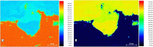
The EDX of these cross-sections thus confirms the widely accepted opinion in the literature (Saha Citation2013; Antunes et al. Citation2014; Inouye, Ishii, and Kaneko Citation1972; Misawa, Hashimoto, and Shimodaira Citation1974; Montoya et al. Citation2013; Morcillo et al. Citation2013; Morcillo et al. Citation2011; Oh, Cook, Balasubramanian et al. Citation1999; Yamamoto, Katayama, and Kodama Citation2000; Yamashita et al. Citation2001; Evans Citation1992; Rohberge Citation2018) that the corrosion layer near the substrate consists more of an oxide mixture γ-Fe2O3/Fe2O4, while the outer layers closer to the atmosphere of the surface environment seem to contain more iron oxyhydroxides. However, a closer look at such EDX mappings reveals an accumulation of iron oxyhydroxide accumulations inside the regions of dissolved ferrite grains.
shows the HR-SEM images of the corroded surface of the flat steel profile surface typical for most of the headgeaŕs surface appearance. upper left provides an overview of a region severely affected by pitting corrosion. As shown in the close-up ( upper right), the corrosion products at the pit margins exhibit a laminar structure. This was found to be typical for lepidocrocite (γ-FeOOH) (Morcillo et al. Citation2011, Citation2013; Montoya et al. Citation2013; Tewari et al. Citation2016). A close-up of a smooth surface area in the vicinity of the pit in lower left shows a spheric, rosette-like, structure of the corrosion products ( lower right). These can be assigned to goethite (α-FeOOH) (Morcillo et al. Citation2011, Citation2013; Montoya et al. Citation2013; Tewari et al. Citation2016). In general, lepidocrocite was found in the more corroded areas of this sample, while goethite was always associated with smoother surfaces.
Figure 9. High resolution (HR) SEM images of the corroded flat steel profile surface. Upper: overview of an extensively corroded region (left); close-up exhibiting laminar lepidocrocite (right). Lower: close-up of a less corroded region (left); close-up exhibiting rosette-like goethite (right).
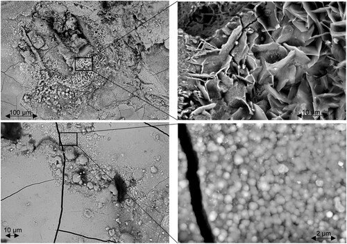
This can be taken as additional evidence that goethite represents a more stable oxyhydroxide form than lepidocrocite (Oh, Cook, and Townsend Citation1998; Yamashita et al. Citation1998; Oh, Cook, Balasubramanian et al. Citation1999; Oh, Cook, and Townsend Citation1998; Hara et al. Citation2001; Asami and Kikuchi Citation2003; Saha Citation2013). It should also be mentioned in this context that according to the existing literature lepidocrocite transforms into goethite during long-term exposure to atmospheric corrosion (Townsend, Simpson, and Johnson Citation1993; Oh, Cook, and Townsend Citation1998, Citation1999; Yamashita et al. Citation1998; Oh, Cook, Balasubramanian et al. Citation1999; Yamashita et al. Citation2001; Asami and Kikuchi Citation2003; Balasubramanian, Kumar, and Dillman Citation2003; Hara et al. Citation2001; Saha Citation2013).
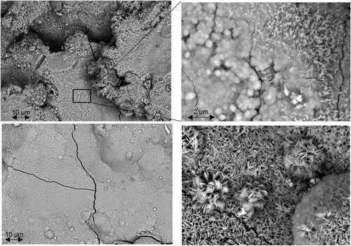
HR-SEM images of the angular steel profile surface are shown in . A close-up of a more severely corroded region is shown in upper left. At even higher magnification ( upper right), it can be seen that the major part of this region consists of rosette-like goethite. Small sections also show a laminar corrosion product on top of goethite. Considering the literature (Morcillo et al. Citation2011, Citation2013; Montoya et al. Citation2013; Tewari et al. Citation2016), it is likely that this represents freshly formed lepidocrocite not yet transformed to goethite. It should be noted that this steel profile has been exposed for 90 years to atmospheric corrosion in the semi-arid climate of the Otavi Mountain Land and thus 35 years longer than the above discussed flat profile. This might be an indication that the transformation from lepidocrocite into goethite under these atmospheric corrosion conditions might require much longer than 60 years of exposure. A close-up of a smoother surface region of the angular steel profile exhibiting less severe corrosion is shown in lower left. Interestingly, the higher magnification in lower right shows a laminar fine-crystalline structure of such regions. Consistent with the existing literature, this structure represents a very stable goethite formed after very long exposure times (Morcillo et al. Citation2011, Citation2013; Montoya et al. Citation2013; Tewari et al. Citation2016).
Figure 10. HR-SEM images of the corroded angular steel profile surface. Upper: overview of extensively corroded region (left); close-up exhibiting lamellar lepidocrocite on top of rosette-like goethite (right). Lower: close-up of a less corroded region (left); close-up exhibiting goethite transformed from a rosette-like structure to a more crystalline structure (right).
The HR-SEM investigations confirmed that goethite is a more stable oxyhydroxide than lepidocrocite. However, the formation of corrosion products depends on the corrosion system. This means that in addition to the type of steel, the composition of the electrolyte, and thus the composition of the surrounding atmosphere influences the corrosion process.
For instance, a slightly acidic electrolyte due to the presence of SO2 in the atmosphere enhances the transformation of lepidocrocite into goethite. The concentration of sulphate and the temperature affect this process (Morcillo et al. Citation2011, Citation2013; Montoya et al. Citation2013; Tewari et al. Citation2016). The wet-dry cycles also have an impact on the formation of the corrosion layer.
The HR-SEM investigation of the two steel samples shows that most of the long-term corrosion layers consist of goethite which protects the steel from further attack. Most of the steel profiles at the Shaft #1 headgear at Tsumeb still retain their original thickness even after almost a century of exposure. However, locally shallow pitting corrosion with pits up to 0.5 mm deep was identified in the cross-sections.
From the conservation perspective, the firm and protective iron oxide layers should be preserved while more loose corrosion products that further promote deterioration need to be removed. Such products mainly occur especially in or near shallow surface pits and can weaken the existing steel profiles. It is thus necessary to prevent further pitting corrosion, as well as crevice corrosion underneath rivet heads, overlapping profiles, and gusset plates. This can be achieved by a suitable protective coating.
Potentiodynamic measurements
For a closer insight into the protective effect of the Owatrol Oil® coating with and without UV-blocker additions versus the already existing corrosion layers the respective scans of the potentiodynamic measurements are summarized in .
Figure 11. Potentiodynamic diagrams (E–I curves) of the flat profile mild steel surface. Upper: potentiodynamic diagrams of the flat profile mild steel surface in the non-weathered condition. Lower left: I–E curves of weathered (red line) and the non-weathered (black line) alkyd resin coated surface. Lower right: I–E curves of the weathered alkyd resin coated surface and that coated with UV-blocker addition.
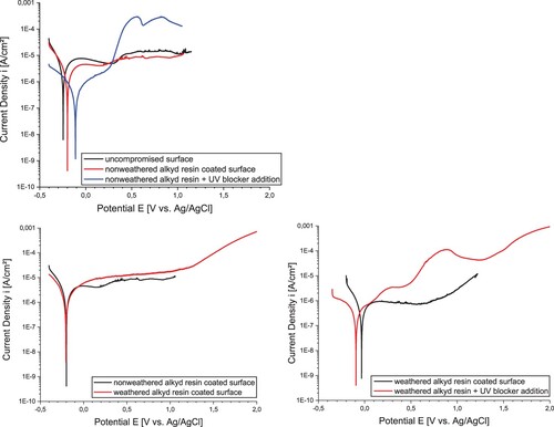
The comparison of the corrosion behavior of the non-weathered sample to the samples with different coatings is compared in (upper). In contrast to polarization diagrams of mild steel surfaces published elsewhere (Nujoma Citation2009), the non-weathered and non-coated surface (black line) exhibits a significantly flattened anodic branch indicating that there is some semi-passive behavior over a quite large potential range. A first, but still minor potential increase can be identified at about 300 mV. However, the curve remains quite flat, up to potentials of over 1V. This indicates a strong corrosion resistance of the long term corrosion layer on the surface.
In comparison, the sample coated with Owatrol Oil® (red line) exhibits a slightly higher equilibrium potential and a slightly lower anodic current density over the entire potential range. The corrosion resistance of the surface seems thus to be slightly improved by the Owatrol Oil® coating.
However, the Owatrol Oil® + UV stabilizer coating system (blue line) reveals a completely different potentiodynamic behavior. While the equilibrium potential is slightly increased, significant activation of the steel surface occurs already at around 300 mV. Such behavior has been confirmed by several tests and it indicates that the UV stabilizers used in this study counteract the corrosion protection provided by both the long-term corrosion products and the Owatrol Oil® coating.
(lower) summarizes the potentiodynamic tests for the long-term corroded mild steel surface preserved with Owatrol Oil® with and without UV-blocker additives after accelerated aging for two weeks in the climate chamber. lower left shows the potentiodynamic response of a sample coated with Owatrol Oil® after artificial weathering (red line) versus a sample in the non-weathered condition (black line). The curves show the same equilibrium potentials and the current density–potential curve also have a very similar shape. This shows that the weathering does not affect the corrosion protection achieved by the Owatrol Oil® coating, i.e. it indicates that the coating does provide sufficient protection under the respective climatic conditions.
lower right shows a comparison of samples coated with Owatrol Oil® (black line) and Owatrol Oil® + UV stabilizers (red line) after two weeks of artificial weathering. As without weathering, the surface coated with added UV stabilizers shows a significant increase in anodic current density without any signs of semi-passive behavior. In addition, the equilibrium potential of this surface decreased by about 50 mV. Even after exposure to the high UV-radiation in the climate chamber selected for this study, the UV-stabilizing additives simply show no positive effect and, even worse, cause a significant decline in semi-passive behavior in both the non-weathered and the weathered condition.
Conclusions
The results of the present study led to the following conclusions regarding the preservation of the Tsumeb Shaft#1 headgear:
The two examined steel profiles from the 1920s and the 1960s were produced from high-quality mild steels at the time. The material from the 1960s was identified as Thomas Steel, while that from the 1920s was identified as Siemens-Martin Steel. Considering that only 50% of German steels were produced in this modern technique in these times obviously only the best materials were chosen for the headgear components delivered to Africa.
The predominant long-term corrosion products identified on the two mild steel samples which were exposed to the semi-arid climate of the Otavi Mountain Land were lepidocrocite (α-FeOOH) and goethite (γ-FeOHH). There is evidence that lepidocrocite is converted to the more stable goethite in the warm semi-arid climate at Tsumeb under long-term exposure. Consistent with the majority of studies reported in the literature, goethite formed directly on the steel surface of the headgear while also partly fresh lepidocrocite was found in the skyward facing part of the corrosion layers. This at least provides some indications that lepidocrocite is transformed into a more stable goethite under long-term exposure of the two headgear steels in the prevailing climate, as previously reported with respect to exposure of such materials to rural marine and industrial climates.
In both steels, dissolution of complete ferrite grains was observed at the interface between the steel and the corrosion layers. The fact that these areas are still partly surrounded by the more corrosion resistant and carbon enriched pearlite indicates that long-term exposure of old mild steels might reveal phenomena similar to selective corrosion. This opens up future research topics, including clarification of the localized corrosion mechanisms and respective prevention at rivet heads, overlapping profiles, and gusset plates to prevent further damage of old mild steel structures.
Short-term climate chamber tests and subsequent potentiodynamic measurements proved to be suitable tools to evaluate the corrosion resistance of mild steels with and without coatings after long-term exposure in semi-arid climates.
Long-term corrosion products on mild steels exhibit a semi-passive behavior over a wide potential range. The measured current densities were somewhat higher than with completely passivated steels. Nevertheless, a certain protective effect can be expected from the corrosion layer. Therefore, the stable long-term corrosion products should not be removed during conservation treatment.
The protective effect of the long-term corrosion products can be enhanced by an additional coating with Owatrol Oil®, while the authentically aged surface of the headgear is preserved. The coating should be applied carefully to the entire surface, in particular in the vicinity of narrow crevices to block further access of oxygen and water. To achieve this by spraying the substance onto large-scale structures, like the Shaft #1 headgear in Tsumeb, it is recommended to dilute the Owatrol Oil® at least to a limited extent. This also prevents a too glossy appearance of large-scale structures after such treatment.
The addition of the specific UV stabilizer mixture used in this study reduces the protective effect of the Owatrol coating. Presumably the radical scavanger Tinuvin® 292 interferes with the drying of Owatrol Oil®. Presumably, the oil component might be crosslinked through the incorporation of oxygen. This process involves radical reactions that may be impaired or retarded if there are not enough free radicals available. This assumption is also supported by the extended drying time of Owatrol Oil® with added UV stabilizers, which was observed during this study.
Since the protective effect of the coating is reduced by long-term outdoor exposure due to decomposition, the headgear will have to be re-coated at regular intervals. Thus, the coating should be inspected regularly. Within the first year of exposure after conservation, no changes of the coating and its thickness have been observed. Currently, it has been suggested to inspect the complete headgear every three months, i.e. two times in every dry and rainy season. The inspection plan will be adapted if any thickness reduction is noticed. However, as another benefit of the Owatrol Oil® used here, it does not have to be removed before recoating.
The on-site study combined with short-term artificial weathering tests and potentiodynamic measurements enabled a profound selection of suitable anti-corrosion coatings for the riveted steel headgear at Shaft #1 in Tsumeb, Namibia. The Owatrol Oil® coating without the addition of UV stabilizers has been successfully applied to the entire steel structure. Long-term observation of the headgear will show if and when the coating has to be renewed. However, it is expected that the corrosion protection achieved with Owatrol Oil® in this warm, semi-arid climate will be quite similar to that in previously studied temperate climates. This not only opens up new perspectives for upcoming conservation projects at the Tsumeb mining site, but also for industrial heritage conservation on the African continent in general.
Acknowledgements
The authors are extremely grateful to Mrs. Nadine Doebele, German Federal Foreign Office in Berlin for her great support and continuous interest in the progress of the project. The project has been carried out in close cooperation between HTW and BAM and the authors would like to thank especially Dr. Volker Wachtendorf and Prof. Dr. Gert Nolze for their helpful support during the weathering tests and for the SEM investigations, respectively. The authors also would like to convey their sincerest gratitude to the chair of the Tsumeb Museum Association, Jens Frautschy, to the Managing Director and Vice President, Zebra Kasete, and all his colleagues from Dundee Precious Metals Tsumeb for their tireless and overwhelming support of the onsite work as well as to the Tsumeb Municipality, especially to Karolina Damaseb and Stella Imalwa, for their continuous interest and administrative assistance on the pathways to continue the project.
Disclosure statement
No potential conflict of interest was reported by the authors.
Additional information
Funding
References
- Antunes, R. A., R. U. Ichikawa, L. G. Martinez, and I. Costa. 2014. “Characerization of Corrosion Products on Carbon Steel Exposed to Natural Weathering and Accelerated Corrosion Tests.” International Journal of Corrosion 11: 419570.
- Asami, K., and M. Kikuchi. 2003. “In-depth Distribution of Rusts on a Plain Carbon Steel and Weathering Steels Exposed to Coastal-Industrial Atmosphere for 17 Years.” Corrosion Science 45: 2671–2688.
- Balasubramaniam, R., A. V. Ramesh Kumar, and P. Dillman. 2003. “Characterization of Rust on Ancient Indian Iron.” Corrosion Science 85: 1546–1555.
- Evans, U. R. 1992. The Corrosion and Oxidation of Metals, Vol. 11. New York: VCH Publishers.
- Fait, J. 2017. Tsumeb 1900–2015 – Namibiás Industrial Heritage, Edition Exclusive for the Tsumeb Museum. Windhoek: Tsumeb.
- Fait, J. 2019. Kupfer, Kolonialismus, Kapital – Das Bergwerk Tsumeb, Namibia (Copper, Colonailsm, Capital – The Mine Tsumeb, Namibia). Hamburg: Diplomatica.
- Inouye, K., S. Ishii, and K. Kaneko. 1972. “The Effect of Copper (II) on the Crystallization of a-FeOOH.” Zeitschrift für allgemeine anorganische Chemie 391: 86–96.
- Jassmann, R. 2020. “Das Fördergerüst am Schacht 1 der Tsumeb Mine (The Headgear at Shaft #1 of the Tsumeb Mine).” MA Thesis, HTW Berlin.
- Hara, S., K. Kashima, H. Kishikawa, H. Miyuki and T. Misawa. 2001. Evaluation on the Protective Ability by the Potential of Steel with Rust Layer Related to the Composition of the Rusts Formed on the Weathering Steel Bridges Using Ternary Diagram, Tetsu-To-Hagane/Journal of the Iron and Steel Institute of Japan, 87: 43–48.
- Koller, J., and U. Baumer. 2000. “Organische Überzüge auf Metallen, Teil 2: Wachse und Emulsionen (Organic Coatings on Metals, Part 2: Waxes and Emulsions).” Arbeitsblätter der Restaurierung (Working Pages of Restauarion) 33 (2): 227–241.
- Langenberg, P. 1995. “Bruchmechanische Sicherheitsanalyse anrissgefährdeter Bauteile im Stahlbau (Fracture Mechanics Safety Analysis of Crack-Sensitive Structural Engineering Components).” Dr.-Ing. Thesis, RWTH Aachen, Aachen, Germany.
- Mazzon, C., P. Letardi, and S. Brüggerhoff. 2021.“ Development of monitoring techniques for coatings applied to cultural heritage.” Accessed May 2021. http://bigstuffheritage.org/wp-content/uploads/
- Misawa, T., K. Hashimoto, and S. Shimodaira. 1974. “The Mechanism of Formation of Iron Oxide and Oxyhydroxides in Aqueous Solutions at Room Temperature.” Corrosion Science 14: 131–149.
- Montoya, P., I. Diaz, N. Granizo, and M. Morcillo. 2013. “An Study on Accelerated Corrosion Testing of Weathering Steel.” Materials Chemistry and Physics 142 (1): 220–228.
- Morcillo, M., B. Chico, I. Diaz, H. Cano, and D. De la Fuente. 2013. “Atmospheric Corrosion Data of Weathering Steels. A Review.” Corrosion Science 77: 6–24.
- Morcillo, M., D. De la Fuenta, I. Díaz, and H. Cano. 2011. “Atmospheric Corrosion of Mild Steel.” Revista de Metalurgia 47 (5): 426–444.
- Notis, M. R. 2002. “A Ghost Story: Remnant Structures in Corroded Ancient Iron Objects.” MRS Proceedings 712: II5.4.
- Nujoma, S. 2009. “Copper – Its Geology and Economic Impact on the Development in Namibia, Zambia and the Democratic Republic of the Congo.” MSc Thesis, University of Namibia, Windhoek, Namibia.
- Oh, S. J., D. C. Cook, R. Balasubramanian, and M. Yamashita 1999. “The Role of Goethite in the Formation of the Protective Corrosion Layer on Steels.” Hyperfine Interactions 122 (1-2): 59–70.
- Oh, S. J., D. C. Cook, and H. E. Townsend. 1998. “Charcterization of Iron Oxides Commonly Formed as Corrosion Products on Steel.” Hyperfine Interactions 112: 59–66.
- Oh, S. J., D. C. Cook, and H. E. Townsend. 1999. “Atmospheric Corrosion of Different Steels in Marine, Rural and Industrial Environments.” Corrosion Science 41: 1687–1702.
- Rohberge, P. R. 2018. Corrosion Basics. 3rd ed. Houston, TX: NACE International.
- Saha, J. K. 2013. Corrosion of Constructural Materials in Marine and Industrial Environment. New Delhi: Springer.
- Schnorbus, H. 2000. Die Geschichte der Otavi Minen AG (The History of the Otavi Mining PLC). Eschborn: Otavi Minen AG.
- Scholz, A., and J. Frautschy. 2019/2020. Tsumeb Museum Archive and Personal Communications. Windhoek: Tsumeb Museum.
- Schönberg, H. 1997. Die technische Entwicklung der Fördergerüste und -türme des Bergbaus [The Technical Development of Mining Headgears and Towers]. Munich: Die Architektur der Förder- und Wassertürme.
- Soehnge, G. 1967. Tsumeb – A Historical Sketch. Windhoek: S. W. A. Scientific Society.
- Tewari, N. K., A. Kundu, R. Nandi, et al. 2016. “Microstructural Characterisation and Corrosion Performance of old Railway Girder Bridge Steel and Modern Weathering Structural Steel.” Corrosion Science 113: 57–63.
- Townsend, H. E., T. C. Simpson, and G. Johnson. 1993. ”Structure of Rust on Weathering Steel in Rural and Industrial Environments.” Proceedings of the 20th International Corrosion Congress, Vol. 2, Houston, TX: NACE, 624–641.
- Valet, A. 1996. Die Technologie des Beschichtens – Lichtschutzmittel für Lacke [Technology of Coating – Light Protection Substances for Laques]. Hannover: C. P. Vincentz.
- Vedder, H. 1938. South West Africa in Early Times. Translated by C. G. Hall. Oxford: Oxford University Press.
- Wideland. n.d. “Wipalat Zubehör (Wipalat Accessories).” https://www.wieland-edelmetalle.de/wordpress/wp-content/uploads/2019/10/Abdecklack-gelb.pdf
- Yamamoto, M., H. Katayama, and T. Kodama. 2000. “Microstructural Analysis of Rust Layers on Weathering Steels Exposed at Rural and Coastal Areas.” Tetsu-to-Hagane 86 (9): 578–583.
- Yamashita, M., A. Maeda, H. Ushida, et al. 2001. “Crystalline Rust Compositions and Weathering Properties of Steels Exposed in Nation Wide Atmospheres for 17 Years.” Journal of the Japanese Institute of Metals 65: 967–971.
- Yamashita, M., H. Nagano, T. Misawa, and H. E. Townsend. 1998. “Structure of Protective Rust Layers Formed on Weathering Steels in Industrial Atmospheres of Japan and North America.” ISWIJ International 38 (3): 285–290.