
ABSTRACT
The extensive usage of railway infrastructure demands a high level of robustness, which can be achieved partly by considering (and managing) the track and rolling stock as one integral system with due attention to their interface. A growing number of infra managers consider, in this framework, the track-friendliness of vehicles that have access to their tracks as a key control parameter. The aim of this study is to provide further insight into potential contributions to track-friendliness, assessed in relation to track deterioration mechanisms and cost, understanding how potential benefits are best to be utilised. Six proposed freight bogie design measures are evaluated with respect to the improvement in curving behaviour, switch negotiation and related track degradation mechanisms. To this purpose a sensitivity analysis has been carried out by means of track–train simulations in the VAMPIRE® multi body simulation software. Additionally, the impact on track deterioration costs has been calculated for those track-friendly design modifications identified as most promising. Conclusions show that the standard Y25L freight bogie design displays rather a track-friendly behaviour. Tuning the primary yaw stiffness shows a high potential to further improve track-friendliness, significantly reducing track deterioration cost at narrow radius curves and switches (by, respectively, 30% and 60%). When calculating the overall deterioration cost for the travelled route, the calculation model should include a well-balanced representation of switches and narrow radius curves.
1. Introduction
Maintenance cost associated with wear and fatigue damage at the wheel–rail interface are dominating the budget of many infrastructure manager and train operating company, with switch maintenance often claiming a disproportionate amount of the overall budget. The Innotrack technical report [Citation1] concludes ‘bad track geometry’, ‘rail cracks/fatigue’ and ‘switch wear’ to be the top three of reported main track problems. Track geometry degradation is strongly connected to the quality of the support conditions in combination with track forces induced either by trains or temperature. From the occurring wear and fatigue features it is understood that this damage type is strongly connected to track layout, especially curved track sections. Consequently the curving behaviour of a vehicle, and related level of creep forces, plays an important role in occurring wear and fatigue loading at the wheel–rail interface. Apart from track radii below 2000 m, vehicle curving behaviour is particularly challenged at the diverging route through a turnout. Öberg and Andersson [Citation2] identify three deteriorating mechanisms, together determining the overall track degradation cost. In accordance with the [Citation1] reported main track problems, the identified mechanisms are track settlement, component fatigue of the super structure and wear and rolling contact fatigue of rails. These mechanisms are governed by the static and dynamic wheel forces and levels of creepage between wheel and rail of which magnitudes are mainly determined by vehicle, track, interface and operational characteristics. Measures that act on these forces and creepage levels will have a direct impact on the overall track degradation and related maintenance cost. Examples of track-related measures are, for example, the application of rail profiles with gauge corner stress relieving properties [Citation3], the local tuning of track elastic properties to reduce the dynamic forces on track components such as the crossing point [Citation4], and track alignment optimisation (e.g. intervention on variations in track alignment or level of cant deficiency) as described in [Citation5]. Punctual and proper maintenance regarding the quality of the running surface and track geometry will further contribute as will the monitoring of the borne tonnage, for example, by weigh-in-motion systems located at key points in the network, to control (dynamic) wheel load especially in relation to developing wheel out-of-roundness. An example of interface management aiming to reduce track forces is the application of wheel–rail lubrication. Searching to increase wheel lifetime, alternative wheel profiles have been designed to reduce the acting wheel–rail forces [Citation6]. Recent developments in vehicle bogie design aim, among others, to further reduce wear and fatigue loading of track and wheels. Bogies that fulfil these conditions are considered to behave ‘track-friendly’. From the viewpoint of overall system performance, infrastructure managers will have an interest in the level of track-friendliness of the vehicles that have access to their track.
From the understanding that train characteristics affect infrastructural degradation differently, inducing different levels of cost, train exploitation should be priced accordingly. To increase efficiency in current pricing schemes, the introduction of differentiated track access charges based on wear and tear from different vehicle types has been discussed [Citation7]. Several European rail infra providers (Network Rail, Swiss Federal Railways) have now started to incorporate track-friendliness into their track access pricing schemes. Target here is to allocate the direct cost to individual trains, incidentally stimulating the inflow of track-friendly designs. In this study, in addition to the assessment of track-friendliness with regard to the level of contact forces and track degradation, the impact of the identified track-friendly design modifications on track deterioration also has been monetised, applying the cost calculation model of Öberg and Andersson [Citation2]. For this purpose one of the major freight route in the Netherlands was selected, comparing the deterioration cost per ton-km for each of the different vehicle concepts running on this route.
The objective of the current study is to evaluate a number of railway bogie design measures regarding their contribution to track-friendliness, assessed in relation to track deterioration mechanisms and cost, understanding how potential benefits are best to be utilised. Bogie design improvements related to freight transport and their impact to Dutch track are of special interest here. For this purpose a sensitivity analyses has been carried out by means of track–train simulations within the VAMPIRE® multi body simulation software, also serving as an input to the applied cost calculation model. The novelty of the performed track deterioration study is twofold. Firstly the combination of both a technical and economic assessment regarding track friendly design changes and secondly the focus on critical assets being switches and narrow radius curves. An important result is the finding that within the applied cost calculation model, as introduced in par. 4.2, positive effects from the viewpoint of track availability and overall performance are undervalued.
The structure of this article is as follows: after the introduction, the technical framework is presented in Section 2, discussing vehicle curving behaviour, presenting the identified design modifications, scope of the research and how the simulation results are analysed regarding wear and fatigue behaviour. The dynamic modelling input for the purpose of track-friendliness assessment is introduced in Section 3, with results for both the technical and economic evaluation presented in Section 4. Overall findings are discussed in conjunction in Section 5 followed by conclusions in Section 6.
2. Theoretical framework
In this section vehicle curving behaviour is discussed for the Y25L freight bogie, presenting identified design modifications and how these are analysed regarding wear and fatigue behaviour.
2.1. Vehicle curving behaviour
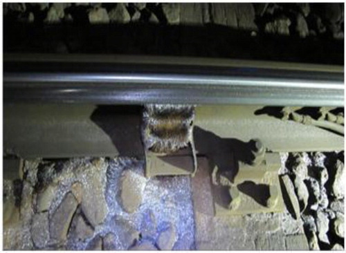
When negotiating a curve with a moderate radius, the rolling radius difference, built up by the lateral displacement of the conical wheels towards the outside of the curve, will create steering forces. These steering forces, when larger than the yaw resistance of the wheelset, lead to a more radial position of the wheelset. However, in sharper curves in general the wheelsets of railway vehicles suffer from under-steer. Because of the angle of attack lateral slip will be generated at the wheel–rail contact patch, where the guiding wheel of the leading axle normally is dominant with respect to tangential forces and slip levels. Lateral slip of both wheels is directed towards the inner side of the curve. These contact forces and resulting stresses can lead to plastic deformation, wear and rolling contact fatigue (RCF) damage at the rail head and wheel tread (Figures and ). Consequently, demanded maintenance is high; for example, inspection, grinding, repair welding and rail replacement at track and wheel re-profiling and replacement at the workshop.
Figure 1. Wheel tread with RCF crack damage.
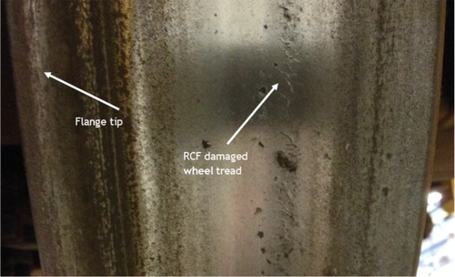
Figure 2. Severely worn narrow radius track section with wear debris at ballast and collecting magnet.
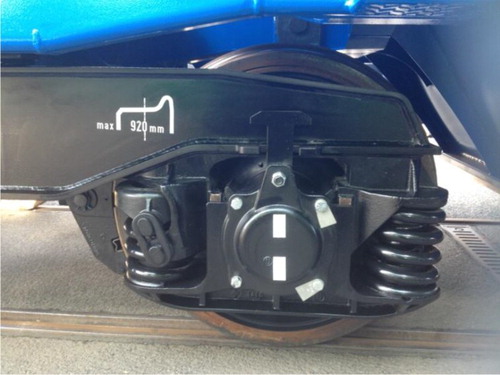
Compared to modern-day passenger vehicles, the bogie design of freight vehicles is often more basic, aiming for robustness, not necessarily at improved curving behaviour. In Europe the most commonly used bogie designed for freight wagons is the two-axle bogie type ‘Y25L-UIC’ (L stands for the French word ‘Lourd’ which translates in English to Heavy). The bogie Y25L was developed by the French National Railway SNCF and standardised by the (International Union of Railways) UIC. As described in [Citation8] the bogie Y25L primary suspension consists of a set nested coil springs (with a bi-linear characteristic for tare/laden ride) and a single Lenoir link providing vertical and lateral frictional damping (). The friction force depends on the vertical load. The longitudinal axle box clearance is 4 mm, unidirectional, allowing a certain yaw angle. After this small amount of longitudinal clearance has been exceeded, the longitudinal stiffness will rise steeply. Therefore the wheelsets can steer themselves in curves as long as the 4 mm clearance is not fully consumed. For curves with a radius below 600 m this clearance is exceeded, and relatively poor curving behaviour as well as high lateral wheel–rail forces are to be expected [Citation9]. From the viewpoint of efficiency, freight wagons are often loaded to their maximum, reaching the allowed track axle load which in the Netherlands is 22.5 ton. The bogie Y25L is admitted for axle loads up to 22.5 ton; the maximum running speed for a wagon fitted with these bogies is 120 km/h when empty and 100 km/h when fully loaded. Although in absolute numbers the annual freight transport in the Netherlands is relatively low compared to passenger traffic (respectively, 40 vs. 144 mio. train km), poor narrow curving behaviour in combination with high axle loads can, depending on curve radii distribution, cause a disproportional contribution of freight transport to track degradation. Achieving improved track-friendliness of freight bogies therefore can significantly contribute to improving the whole system performance, resulting in a more sustainable rail transport system. Identification and quantification of performance-based design principles can further support this development.
Figure 3. Y-25 primary suspension consisting of a set nested coil springs and a single Lenoir link.
2.2. Measures to improve track-friendliness
To improve track-friendliness of freight bogies, over the years a vast number of bogie design innovations have been considered and reviewed by the industry. The vast number of Europe’s 400,000 strong freight wagon fleet, however, is still fitted with classic bogies. A parametric a study of freight vehicle effects on rail surface damage is presented in [Citation10]. Regarding the design of the vehicle it was concluded that the characteristics of the primary yaw stiffness (PYS) significantly influence the resulting rail surface damage. The SUSTRAIL project [Citation11] has studied freight bogie design optimisation of the primary suspension by the use of double Lenoir link primary suspension, allowing opposite longitudinal displacement at the wheelset’s both primary suspensions, thus facilitating larger yaw angles of the wheelsets while still utilising standard components. Within [Citation11] further assessment of wheelset guiding design optimisation included the benefit of linkages providing longitudinal stiffness between the axle boxes using a radial arm (also known as ‘trailer arms’). These radial arms are connected to the bogie frame by pivot bushes. For this type of suspension, the PYS is dominated by the radial stiffness of the radial arm pivot bush. This rotational stiffness of the wheelset within the bogie frame strongly determines the radial setting of the wheelsets in curves, having a direct effect on the contact conditions, the level of creepage and the lateral forces at the wheel–rail contact patch. Vehicle stability on straight track and curving ability in switches and curves however impose a conflict upon the vehicle designer. Recent developments in suspension design provide the required high PYS stiffness at high loading frequencies to ensure stable running, together with low PYS stiffness at low frequencies, resulting in moderate loading when negotiating a curve or switch.
This suspension behaviour is achieved through the application of new elastic components with a characteristic that is dependent on loading frequency. As presented in [Citation12] these so-called Frequency Selective Stiffness or ‘hydrobush’ elements can, when applied at the radial arm pivot bush, lead to a significant reduction of rail and wheel surface damage. An overview of further design optimisation measures is presented in [Citation8].
The research presented here focuses on the improvement of switch negotiation and curving performance and related wheel–rail contact stress levels by optimisation of the steering behaviour of Y25L freight wagon bogies. Starting from the above-identified design optimisation measures a parametric study has been set up, investigating the effects of several freight bogie design parameters on rail surface damage. A sensitivity analysis was carried out by vehicle dynamic simulations, performed with respect to the characteristics of primary and secondary suspension, unsprung mass and cross anchor application. Additionally, the impact on track deterioration cost has been calculated for the track-friendly design modifications identified as most promising. Quantifying the claimed benefits of these innovations in bogie design to the overall rail transport will support decision making.
2.3. Assessment of track-friendliness
Assessment of the level of track-friendliness with regard to curving behaviour and switch negotiation is carried out in terms of wear and Head Check damage development, derived from the RCF damage function as presented in [Citation13]. The key parameter in this part of the assessment is the parameter Tγ (‘T-gamma’), in which longitudinal and lateral tangential forces and creepages are combined to calculate the energy dissipated at the wheel–rail contact patch. Tγ can be used as an output value indicating the expected damage development with respect to wear and RCF development. The relation between the occurrence of visible RCF damage in R220 grade rail material is established in the RCF damage function as presented in . In this graph, Tγ is plotted on the horizontal axis. On the vertical axis, the RCF damage index is plotted. The RCF damage index equals 1 divided by Nf: the number of loading cycles until the first visible Head Check damage occurs. The ‘Wear number’ Tγ is a direct output from the VAMPIRE® multibody analysis. The energy dissipation value Tγ is determined at the first outer wheel for curves with different radii and for switch panel negotiation. Note that spin moment and spin creepage terms are not included in [Citation13]. The spin contribution, however, is included in the output of the here performed simulations. Quantifying the relative contribution of lateral, longitudinal and spin creepage to the dissipated energy for a 300 m curve radius [Citation14] showed the relative spin contribution to be in the order of 8%, not influencing the overall assessment result. The impact on track geometry degradation have been assessed through simulations on a tangent track, evaluating the level of track forces.
Figure 4. RCF-damage function for rail grade R220 [Citation13].
![Figure 4. RCF-damage function for rail grade R220 [Citation13].](/cms/asset/4c9acb96-2659-43fc-8786-4940d73a4b40/nvsd_a_1421766_f0004_b.gif)
3. Vehicle–track interaction model
Presented in this section are the applied track and vehicle models to assess the track-friendliness of the proposed bogie design modifications.
3.1. Bogie and vehicle models
Based on data presented in [Citation15] a model of the Y25L bogie was set up in VAMPIRE®, using the also presented simulation and measurement results for purpose of validation. Based on the validated Y25L bogie model, six further bogie vehicle models were set up, in order to assess the following design modifications:
Bogie with double Lenoir linkage
Bogie with trailer arms, fitted with conventional bushes
Bogie with trailer arms, fitted with hydrobushes
Bogie with reduced secondary lateral stiffness
Bogie with reduced unsprung mass
Bogie with cross-anchors and trailer arms, fitted with conventional bushes
For the Y25L bogie design the yaw stiffness is determined by the longitudinal stiffness between the axle boxes and bogie frame. For the longitudinal direction, the primary suspension is modelled as a tri-linear stiffness element (in fact a linear spring element with two bump stops), in parallel with a friction element which produces a friction force proportional to the static and dynamic wheel load. When starting the yaw rotation, the first 4 mm of longitudinal play is consumed at a relatively low stiffness value of approx. 1 kN/mm. After this 4 mm displacement, a nominal longitudinal stiffness value of 10 kN/mm is assumed in accordance to [Citation15]. Three PYS design modifications are analysed here: (1) the double Lenoir linkage, possessing equal characteristics to the single Lenoir with the only difference that the clearance is doubled and the centre position defined as in the middle of this 8 mm. (2) Application of trailer arms with conventional bush: based upon suspension characteristics from conventional trains with max. 22.5 tons axle load and fitted with bogies with trailer arms, chosen linear longitudinal stiffness is 20 kN/mm. Similarly, the axial stiffness was chosen as 5 kN/mm and the conical stiffness as 1 kNm/mrad. Dynamic stiffening was not included here. And (3) application of trailer arms with hydrobush: applied stiffness values are based upon earlier investigation published in [Citation12] (static stiffness 2.8 kN/mm, dynamic stiffness 15 kN/mm). Within [Citation12] it is described how the frequency dependent effect is implemented into the Vampire model. All design modifications were variants of the Y25L bogie.
In order to quantify the benefits of any new design, a benchmark vehicle has been selected based on Y25L bogies with a coal hopper wagon type HHA. The ‘wagon body’, including everything except bogies, is defined in terms of mass, inertia and centre of gravity, both for the tare and laden condition (7 and 22.5 tons axle load, respectively). The wagon body rests on the bogie’s secondary springs. Simulations were carried out in tare and laden condition. The coefficient of friction between block braked wheels and rail is set to f = 0.45, in correspondence to [Citation10].
3.2. Track models
3.2.1. Switch loading
The assessment of switch loading was carried out using a track model of the diverging route through a switch panel, with vehicle speed set to 40 km/h. The most common type of turnout applied in Dutch track has been selected. This turnout has a crossing angle 1 over 9, with switch radius 195 m as presented in [Citation12].
3.2.2. Curving
The track input for curving behaviour assessment consists of a set of right-hand curves with radii 250, 500, 750, 1000, 1500, 2000 and 2500 m. The cant is set to 50 mm for the radii from 250 m to 1000 m, to 30 mm for 1500 m, and to 0 mm for 2000 m and 2500 m. For each simulation the operational speed is set to a value that results in a cant deficiency of 30 mm. Track irregularities following ERRI B176 type low [Citation16] were applied to the track curving track models, promoting earlier friction break-out of wheelsets and bogie (rail inclination 1:40, track gauge1435 mm). Runs were performed with the UIC 54E5 (anti-head check) rail profile and new (unworn) S1002 wheel profiles.
3.2.3. Track degradation
Assessment with regard to the level of vertical and lateral track forces, and resulting impact to track geometry degradation, has been carried out using 1000 m of as-measured tangent track in the Netherlands with consisting shortwave vertical and lateral track irregularities. The Power Spectral Density (PSD) of measured track irregularities as a function of wavelength show the track geometry recording data not to comprise lateral wavelengths below 6 m and vertical wavelengths below 8 m. The simulated train speeds varied with a maximum of 100 km/h when fully laden and 120 km/h when tare. Runs were performed with the UIC 54E1 rail profile, and new (unworn) S1002 wheel profiles.
4. Evaluation
4.1. Technical criteria
Over 200 simulation runs were performed for this part of the study. All simulations have been executed in VAMPIRE Pro®, version 6.30. All simulation results have been compared with the simulation results for the Y25L reference bogie. Only those results that produced noteworthy differences are discussed in detail.
4.1.1. Primary yaw stiffness
In this section the effect of PYS design modifications is discussed with respect to switch negotiation, curving behaviour and dynamic wheel forces.
4.1.1.1. Switch negotiation
(a–d) present the dissipated energy Tγ development for the different PYS design variations at contact patch areas of the first wheelset during switch negotiation. The horizontal axis represents the position in the track. The switch toe is located at x = 40 m. The left-hand turnout is negotiated in the diverging route. The direction of travel is from left to right (the facing direction). For both the switch panel (position 40–48 m) and closure panel (position 48–63 m), Tγ development is presented for the contact area of the wheel tread/flange root (left wheel:1L, right wheel:1R) and the contact area of the wheel flange (1FL, 1FR). For those locations where simultaneously contact occurs at the running surface of switch rail and stock rail, Tγ values are summed. Summation of Tγ for simultaneous contacts can unwillingly influence the resulting evaluation outcome. However, for the here evaluated situation the load transfer length with simultaneous contact is very short compared to the total length of the switch panel and therefore summation does not influence the resulting prevalent switch panel damage mode (wear or RCF).
Figure 5. Tγ development for the different PYS design variations at the contact patch areas of the first wheelset during switch negotiation. Reference (a), double Lenoir (b), trailer arm with conventional bush (c), trailer arm with hydrobush (d). The right wheel (R) is guiding, 1R/L: wheel tread/flange root contact, 1FR/FL: flange contact.
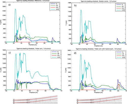
Upon entering the switch, the wheel flange of the leading right wheel comes into contact with the switch rail at approximately 0.5 m behind the switch toe. This results in a steep increase of Tγ. When comparing the Tγ peak values, it can be seen that these are not influenced by the examined PYS design measures. Significant differences, however, can be observed at the wheel tread/flange root contacting area of the switch panel and at both the contacting area of flange and wheel tread/flange root of the closure panel.
Flange contact at the closure panel becomes negligible for the design variants double Lenoir and trailer arm with hydrobush, eliminating side wear loading at this location in track. The application of trailer arms with conventional bushing leads to an increase of PYS compared to the reference situation with resulting Tγ values during switch negotiation well above 200 N, placing its operational window entirely in the region of ‘Wear’. By applying the damage function as shown in , the expected effect of the individual modifications can be understood more clearly. Table presents for each modification the expected damage development at switch and closure panel, based on the operational wear number from the guiding right wheel.
Table 1. Rail damage development type, based on Tγ loading of the guiding right wheel during 1:9 switch negotiation in diverging route.
4.1.1.2. Curving behaviour
presents the simulation results for the different PYS design variations and different curve radii. It shows the quadratic mean (RMS) Tγ value of the outer wheel of the leading wheelset, determined in the full curve. For each design modification these RMS Tγ values are plotted against the curve radius. The results in show that improved curving behaviour, compared to the Y25L reference bogie, only occurs for radii below 750 m. This positive effect is only present for two of the evaluated design modifications; the double Lenoir and trailer arm with hydrobush, and to a lesser extend for the reduced secondary horizontal stiffness. The best narrow radius curving performance is shown by the double Lenoir design, with resulting Tγ values below the damage threshold value down to the 500 m radius curve. As was the case with switch negotiation, it can be seen here that the trailer arm bogie design with conventional bush results in increased Tγ values due to the increased PYS. For the assessed operational conditions, the influence of the cross anchor is negligible.
Figure 6. Tγ development for the different design variations and curve radii.
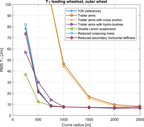
Figure 7. Tγ and lateral force (Y) as a function of the wavelength of the leading wheelset for the reference bogie, bogie with reduced unsprung mass and bogie with reduced sprung and unsprung mass.
The impact of a rubber ring mounted between the Y25L bogie frame and the lower part of the centre pivot was examined by introducing a lateral stiffness to the centre bowl set to 0.2 kN/mm, corresponding the limit value proposed at the EU Seventh Framework Programme SPECTRUM presentation ‘Suspension simulation of a rail freight vehicle for LDHV goods’ (Paris, 8th April 2015). Initially developed for stability improvement, here the potential for curving improvement was examined. The resulting Tγ values for switch negotiation are shown not to be significantly influenced by this design modification, it has only a minor influence on curving behaviour.
A cross anchor is a pair of linkages applied diagonally between the wheelsets. These wheelsets, when yawed by the wheel–rail contact forces, will assume a radial position. Providing diagonal linkages between the wheelsets of the Y25L reference bogie is however not useful, since the combination of these linkages with the single Lenoir dampers would prevent all longitudinal movements of the wheelsets relative to the bogie frame. Therefore, in this research the cross anchor is limited to a combination with the design with trailer arms and conventional bush. The resulting Tγ values do not show a significant influence of this design measure on running behaviour; for the switch negotiation nor for curving, the found Tγ levels are corresponding to those for the trailer arm without cross anchor.
4.1.1.3. Track degradation
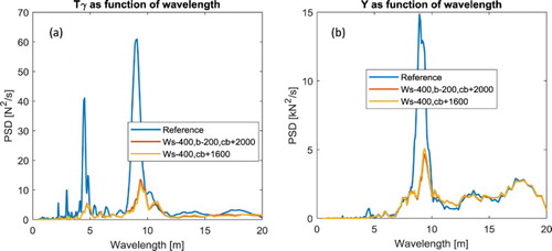
Developments in bogie design are seen to also target the bogie mass for which a reduction can be achieved, for example, by the inboard bearing wheelset concept and hollow axles considerably reducing the unsprung mass together with a low weight bogie frame design. The effect of reducing the unsprung mass of the bogies on track degradation is investigated by examining the forces between wheel and rail in lateral and vertical direction. Reduction of the unsprung mass is implemented in the vehicle model by reducing the mass per wheelset with 400 kg; additionally the mass per bogie frame is reduced with 200 kg. This results in a mass reduction of 1000 kg for each bogie (approx. 20% reduction) and implies 2000 kg of extra freight. To illustrate the effect of the individual changes in mass of bogie frame (sprung) and wheelset (unsprung), simulations have been carried out for the following three configurations (all variants retaining 22.5 tons axle load): (1) Reference Y25, (2) mass of each wheelset reduced with 400 kg (Ws-400) and bogie frame reduced with 200 kg (b-200) adding 2000 kg of extra freight to the wagon and (3) mass of each wheelset reduced with 400 kg (Ws-400) adding 1600 kg of extra freight.
As mentioned in Section 5.2 the track section applied for this analysis is tangent track with measured track irregularities. The applied vehicle speed is 90 km/h, laden. For the laden condition 22.5 ton axle load is applied. The power spectral density of Tγ as a function of the wavelength is presented in (a). It can be seen that a reduction of the unsprung mass results in a significant reduction in Tγ loading.The dominating wavelength of 9 m corresponds to the wavelength of the Klingel motion of a Y25 wheelset. The lateral forces (Y) power spectrum is presented in (b). Reducing the unsprung mass predominantly has resulted in a significant reduction of lateral track forces and associated Tγ. Reduced lateral track forces can expectedly lead to a reduction in track geometry degradation and related maintenance effort and cost. For the vertical track forces, the observed reduction is much smaller.
As mentioned in Section 3.2, the track geometry input data used for assessment of wheel–rail forces does not comprise lateral wavelengths below 6 m and vertical wavelengths below 8 m. It should therefore be noted that track geometry as registered by a measurement coach is not a fully adequate parameter to determine the effect of unsprung mass on track degradation. The unsprung mass has a significant effect on the vertical dynamic wheel–rail force for wavelengths that are shorter than or in the same order of magnitude as the wheel circumference, which is about 3 m. This implies that the unsprung mass plays a crucial role in the degradation rate of points and other switch parts, of insulated joints and potentially of welded connections with insufficient straightness. These components are key assets in the performance of a railway network. For conventional train speeds, the first derivative of the trajectory of the gravity centre of the unsprung mass may exhibit a discontinuity, implying wheel–rail impact conditions (see ref. [Citation17]). This is also true in lateral directions. It has been demonstrated in [Citation17] that in these cases the dynamic contact force is proportional to the mass, which is consistent with both theoretical and field results for P1 peak forces from the literature [Citation18]. The level and frequency content of the dynamic contact force have a direct relationship to the degradation rate of concerned railway structural assets, even apart from the parameter Tγ and induced wear/RCF. It is therefore useful to strive for minimum inertia of unsprung bogie parts.
4.2. Economic criteria
Öberg and Andersson [Citation2] have presented a track deterioration cost calculation model, able to differ between vehicle types based on their characteristics and tendency to deteriorate tracks. The model applies the marginal cost methodology, aiming to determine the additional cost per extra vehicle unit by determining the impact of that vehicle. This model is applied to the present study, assessing the impact of the proposed track-friendly designs regarding track deterioration costs. As a case study, a dedicated freight corridor was selected. The first step in calculating the deterioration cost is to determine the marginal cost level currently for infrastructure in the Netherlands. Next step is to compose a set of VAMPIRE® tracks models, representative for the studied corridor. From the executed simulation runs, input data to the deterioration model is acquired, consisting of Ty wear numbers, guiding forces and dynamic wheel loads. Finally, the deterioration cost per ton-km for each vehicle concept is calculated.
The European 5th frame project UNITE [Citation19] defines marginal social cost as the costs of an additional transport unit (train km for rail). Marginal infrastructure cost is the cost to infrastructure managers of additional traffic, principally maintenance and renewal but potentially also other aspects of operating cost. To calculate marginal costs all impacts have to be determined and calculated, and finally these impacts must be monetised. Marginal cost calculation methods can be very complicated, time-consuming and have high data requirements. A simplified method to determine marginal costs is presented in [Citation20], using average variable costs as a substitute for marginal costs. The proposed simplified approach may provide a lower degree of accuracy compared to the more sophisticated approaches but has the advantage of being relatively easy to apply. In many cases the simplified approach can serve to provide a quick indication of the marginal cost level. For this study the proposed simplified method is used as a set-up for the marginal infrastructure cost calculation. In order to limit the complexity of the study, cost for congestion, air pollution and noise are not considered. Required input data regarding infrastructure cost for maintenance and control is derived from [Citation21]. From this input the calculated marginal cost for ProRail track amounts to 0.0031 €/gross ton kilometres. This is in line with the actual ProRail track access charge for a 650 ton train which in 2013 was set to 0.0035 €/gross ton kilometres.
4.2.1. Dynamic simulations
The selected route, from Roosendaal to Oldenzaal, is 205 km in length with 30% consisting of curved track with a radius below 2000 m. A representative set of track models is designed, covering the various track radii and switches with associated cant. The applied speed profile is based on the maximum allowed line speed for loaded wagons at the different route sections (applied minimum is 40 km/h, maximum 100 km/h). Evaluated vehicle concepts are Y25L reference, Y25L with double Lenoir, Y25L with trailer arm fitted with hydrobush and Y25L with reduced unsprung mass. All concepts are fully laden to 22.5 ton axle load. The applied wheel profile is UIC S1002. To account for the effect of geometrical disturbances regarding wheel–rail forces and corresponding marginal costs, lateral and vertical track irregularities have been generated according to the method provided in report ERRI B176 [Citation22]. To excite frequencies up to 90 Hz, the applied wavelength range is 0.1–200 m. The applied rail profiles are UIC 54E1 on tangent track and UIC 54E5 in curves. The lateral rail to sleeper stiffness is set to a default value of 43 kN/mm, vertical rail to sleeper stiffness to 50 kN/mm. The wheel–rail friction coefficient is set to 0.45. The dynamic simulations direct output consists of the average wear number (Tγ) for the outer wheels (both leading and trailing axle) and quasi-static wheel loads (both vertical and lateral). Also the dynamic wheel load contributions for the frequency content up to 20 Hz and between 20 and 90 Hz are obtained from the VAMPIRE® simulations output. For this purpose, in accordance with UIC code 518 [Citation23], vertical and lateral dynamic wheel forces are filtered after which the 99.85 percentile values are determined.
4.2.2. Impact analysis
The track deteriorating cost calculation model presented by Öberg and Andersson [Citation2] is based on two damage models. The first one, a damage model developed in the 1980s by the ORE (Office of Research and Experiments) is the base for the first two terms in Equation (1), respectively, related to track settlement and super structure component fatigue. The third term of the formula, related to wear and RCF, is based upon the Whole Life Rail Model as developed and experimentally validated by Burstow [Citation13].
For the calculation of the cost of track deterioration the total marginal cost is considered as a mean value of the whole network. The overall cost of track deterioration is composed of the individual share of each deteriorating mechanism. Öberg and Andersson propose a distribution of these mechanisms applicable for the Swedish rail network. Typical for the rail network in the Netherlands is the relative soft sub-structure which, in comparison to the Swedish situation, is expected to raise more issues with track settlement. This is reflected in the distribution applied to the present study, with track settlement responsible for 35% of the marginal cost, component fatigue for 25% and the remaining 40% allocated to wear and RCF of rails. From the calculated marginal cost and applied distribution in deteriorating mechanisms, the marginal average cost coefficients are calculated in relation to the Y25 reference bogie. These coefficients are then used to calculate the marginal cost for the other vehicle concepts. To the initial model of Öberg and Andersson lateral track shift forces were included in the settlement mechanism by adding the term () to first term of Equation (1) (Table ).
(1)
(2)
4.2.3. Marginal cost calculation results
The marginal cost for rail wear and RCF are presented in . These cost are strongly determined by the PYS and related wear energy number Tγ and consequently are seen to increase with decreasing curve radius. The single Lenoir link design, as applied to the Y25L reference bogie and the bogie with reduced unsprung mass, allow the wheelsets to steer radially in curves with radii of 750 m and up. For radii below 750 m the marginal cost for bogies with the single Lenoir design is seen to rapidly go up. The improved yaw stiffness behaviour in narrow radius curves for the double Lenoir and hydrobush design results in decreased Tγ levels in the curve range with radii <750 m, resulting in significant marginal cost reductions compared to the reference bogie. The frequency-dependent stiffness of the hydrobush design, however, is seen to significantly influence its marginal cost development. Especially in larger radius curves and in tangent track with higher vehicle speeds, the introduced track irregularities cause the primary suspension to operate in its relatively high dynamic stiffness range, which results in an increase of Tγ and the related marginal cost compared to the reference bogie. The hydrobush respond to track irregularities and resulting increase in stiffness also results in a marginal cost increase for the other two deterioration mechanisms (track settlement and component fatigue). Important is to mention that the here applied hydrobush stiffness characteristic has not been specially designed for the Y25L bogie. Further tuning of the hydrobush stiffness probably can reduce the marginal cost level for tangent track and large radius curves. From the working principle however, it seems unlikely that for the operational conditions considered here an overall cost level equal to or below the reference situation can be achieved. Compared to the Y25L reference bogie, an improvement in running stability can be expected from the hydrobush design when running at higher speeds (>120 km/h) and when running with empty wagons. Potential beneficial aspects have not been incorporated in this study.
Table 2. Track deteriorating cost calculation terms.
Figure 8. Marginal cost development for wear and RCF in relation to the different bogie designs.
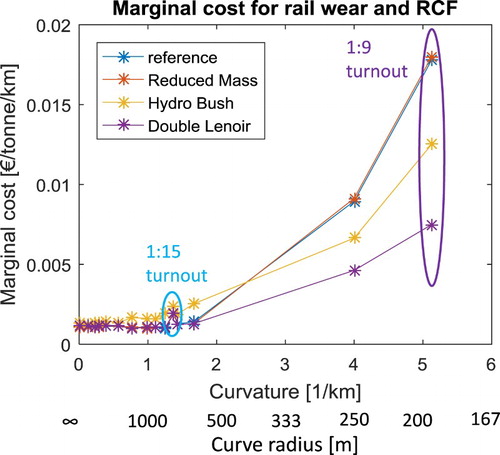
From it is understood that the vehicle concepts with improved PYS behaviour (double Lenoir link and trailer arm with hydrobush) behave more cost friendly in switches and narrow radius curves (R < 750 m). However, since this curve range only represent a small part of the total route, the impact on the overall cost savings is limited. In tangent track and large radius curves the double Lenoir performs equal to the reference: due to its improved behaviour in narrow radius curves it results in a cost reduction for the total route of 1.8%. The hydrobush performs noticeably worse in large radius curves and on tangent track, resulting in a marginal cost increase for the total route of 26%.
When calculating the total cost for the selected route, using Equations (1) and (2), the vehicle concept with reduced unsprung mass provides a 2.8% reduction in cost compared to the reference Y25L bogie design. For a 650-ton freight train, a locomotive with seven maximum loaded wagons, travelling the route Roosendaal – Oldenzaal, this results in a cost saving of 12 euro’s. At the same time the reduced unsprung mass allows an additional load of 2 tons per wagon, resulting for this particular train in an additional 14 tons freight to be transported.
5. Discussion
In this section the results are discussed regarding the assessment of track degradation mechanisms and related track degradation cost calculation.
5.1. Technical
5.1.1. Switch negotiation
The track loads resulting from simulations in the switch panel demonstrate ‘wear’ to be the dominant damage type for the assessed 1:9 turnout. This is the case for theY25L reference design, as well as for the assessed design modifications. Clearly the Tγ peak values occurring when entering the switch panel cannot be reduced by lowering the PYS value. However, at the closure panel, with curve radius 195 m, a significant difference is observed for two of the assessed design modifications, being the double Lenoir linkage and the trailer arm with hydrobush. For these modifications, wheel–rail wear at the flange (gauge face) becomes negligible. Simultaneously the Tγ level at the wheel tread/flange root contacting area is reduced, shifting from ‘wear’ into the ‘RCF’ region for double Lenoir, where the hydrobush loading level remains in ‘wear’. The other investigated design modifications (trailer arm with conventional bush, reduced secondary lateral stiffness, reduced unsprung mass and the cross anchor application) did not result in a significant optimisation in switch loading.
5.1.2. Curving behaviour
For the assessed operational conditions, the reference Y25L bogie displays excellent curving behaviour for curves above 750 m radius, keeping operational Tγ levels below the RCF damage threshold. At the curve radius of 500 m Tγ values are seen to sharply increase, resulting in RCF damage development for all evaluated designs except the double Lenoir design which remains below the RCF damage threshold. Although the trailer arm with hydrobush design results in reduced Tγ values compared to the reference bogie, its Tγ level at 500 m curve radius indicates operation within the RCF region. At 250 m radius, both double Lenoir and hydrobush design modifications are experiencing RCF damage development. Of the other investigated design modifications, only the reduced secondary lateral stiffness leads to improved curving, although minor.
5.1.3. Track degradation
The effect of reducing the unsprung mass of the bogie on track degradation, has been assessed by evaluating the forces between wheel and rail in lateral and vertical direction. It can be observed that reducing the unsprung mass predominantly has resulted in a significant reduction of the lateral track forces, and related Tγ. The observed reduction is closely related to the Klingel movement of the bogie. Reduced lateral track forces will expectedly lead to reduced track geometry degradation and related maintenance effort and cost.
5.2. Economic
The marginal cost are clearly the highest at switches and narrow radius curves: for the reference situation the cost at switches is about 12 times the cost at tangent track. For switches, the double Lenoir design results in a 60% marginal cost reduction for rail wear and RCF compared to the Y25L reference. For the trailer arm with hydrobush a 30% reduction is observed. However, since these switches and narrow radius curves represent only a small portion of the total route length, performance at large radius curves and tangent track is decisive in the overall cost level for the route. This is illustrated by the calculated cost reduction for the route for the double Lenoir being only 1.8%. To account for the degradation of switches and narrow radius curves, being the most vulnerable railway assets both in cost and operation, simply reviewing the overall marginal cost calculation for the route is clearly not sufficient. In [Citation24] reduction in the Variable Usage Charge was calculated for the Spectrum trackfriendly bogie design, using a calculation method that mainly rewarded overall curving behaviour, not considering the travelled route. Resulting variable cost reductions are in the same order of magnitude as those here observed at narrow radius curves and switches.
Because the Y25L reference bogie design possesses a very low PYS at curves with radii from 600 m and up, the impact of the hydrobush element is limited. Significant benefits from this element, however, can be expected when applied to bogie designs with relatively high static PYS values. Not comprising lateral wavelengths below 6 m and vertical wavelengths below 8 m, it should be noted that the evaluated track geometry as registered by the measurement coach at ProRail track currently is not a fully adequate parameter to determine track degradation forces and cost. The significance of these wavelength limits should be further quantified.
6. Conclusions
The potential of proposed design measures regarding the improvement of curving behaviour and switch negotiation of railway freight bogies and related track degradation mechanisms have been studied. For this purpose, a sensitivity analysis has been carried out by means of track–train simulations in the VAMPIRE® multi-body simulation software. Curving behaviour of the standard Y25L freight bogie design, with respect to expected wear and RCF development, is shown to be rather good, keeping operational Tγ levels below the RCF damage threshold for a large range of radii. Only for the evaluated curve radii of 500 and 250 m, RCF development can be expected for the standard Y25L design. Two of the six evaluated bogie design modifications, being the double Lenoir linkage and the trailer arm with hydrobush, both targeting the PYS characteristics, deliver a distinctive contribution to track-friendliness of the Y25L freight bogie. For the assessed conditions the double Lenoir modification expands the curve radii range with Tγ operational levels below the RCF damage threshold to 500 m. Improved switch negotiation is observed for both the double Lenoir and trailer arm with hydrobush design modification, especially for the closure panel in which, for the assessed situation, flange wear is almost eliminated. Reducing the unsprung bogie mass has shown to reduce the lateral track forces, which will expectedly lead to a reduction in track geometry degradation. Other evaluated design modifications did not significantly contribute to improving track-friendliness under the evaluated conditions.
The improved behaviour at narrow radius curves (R < 750 m, switches 1:9) of the vehicle concepts with double Lenoir link and trailer arms with hydrobush provide, respectively, 60% and 30% marginal cost reduction for rail wear and RCF compared to the reference Y25L bogie. However, since this curve range only represents a small part of the total route, the resulting marginal cost in the executed corridor study is dominated by tangent track and large radius curve sections. Although not significantly contributing to the calculated overall cost, measures decreasing the track deterioration for switches and narrow radius curves, being the more vulnerable track elements, are expected to be beneficial from the viewpoint of track availability and overall performance. Currently, this seems insufficiently reflected in the overall assessment result. When calculating the overall deterioration cost for the travelled route, the calculation model should include a well-balanced representation of switches and narrow radius curves. This will support the development of future track access charging, stimulating the design and introduction of vehicles with improved track-friendliness.
Acknowledgements
This research is being carried out by the author under the project number T91.1.12475a in the framework of the Research Program of the Materials innovation institute M2i (www.m2i.nl). The authors wish to acknowledge the support of ProRail.
Disclosure statement
No potential conflict of interest was reported by the authors.
ORCID
Nico Burgelman http://orcid.org/0000-0003-4038-8364
Additional information
Funding
References
- INNOTRACK Concluding Technical Report, UIC – Paris; 2010. ISBN: 978-2-7461-1-1850-8.
- Öberg J, Andersson E. Determining the deterioration cost for railway tracks. Proc Inst Mech Eng F J Rail Rapid Transit. 2009;223(2):121–129.
- Dollevoet R, Li Z, Arias-Cuevas O. A method for the prediction of head checking initiation location and orientation under operational loading conditions. Proc Inst Mech Eng F J Rail Rapid Transit. 2010;224:369–374.
- Markine VL, Steenbergen MJMM, Shevtsov IY. Combatting RCF on switch points by tuning elastic track properties. Wear. 2011;271:158–167.
- Karttunen K, Kabo E, Ekberg A. A numerical study of the influence of lateral geometry irregularities on mechanical deterioration of freight tracks. Proc Inst Mech Eng F J Rail Rapid Transit. 2012;226(6):575–586.
- Vermeij I, Bontekoe T, Liefting G, et al. Optimisation of rolling stock wheelset life through better understanding of wheel tyre degradation. Int J Railw. 2008;1(3):83–88.
- Andersson M. Marginal cost of railway infrastructure wear and tear for freight and passenger trains in Sweden, Swedish National Road and Transport Research Institute (VTI). Eur Transp. 2011;48:3–23.
- Iwnicki SD, Stichel S, Orlova A, et al. Dynamics of railway freight vehicles. Veh Syst Dyn. 2015;53(7):995–1033.
- Stichel S. On freight wagon dynamics and track deterioration. Proc Inst Mech Eng F J. Rail Rapid Transit. 1999;213(F4):243–254.
- Tunna T, Urban C. A parametric study of the effects of freight vehicles on rolling contact fatigue of rail. Proc Inst Mech Eng F J Rail Rapid Transit. 2009;223:141–151.
- Iwnicki S, Bezin Y, Orlova A, et al. The ‘SUSTRAIL’ high speed freight vehicle: simulation of novel running gear design). 23rd symposium on Dynamics of Vehicles on Roads and Tracks (IAVSD 2013) 2013; Qingdao, China.
- Hiensch EJM, Wiersma P. Reducing switch panel degradation by improving the track friendliness of trains. Wear. 2016;366–367:352–358.
- Burstow MC. Whole life rail model application and development for RSSB – continued development of an RCF Damage Parameter. AEATR-ES-2004-880. 2 September 2004.
- Alarcón GI, Burgelman N, Meza JM, et al. The influence of rail lubrication on energy dissipation in the wheel/rail contact: a comparison of simulation results with field measurements. Wear. 2015;330–331:533–539.
- Molatefi M, Hecht M, Kadivar MH. Critical speeds and limit cycles in the empty Y25-freight wagon. Proc Inst Mech Eng F J Rail Rapid Transit. 2006;220.
- ERRI B176 RP1. Preliminary Studies and Specifications, Utrecht, the Netherlands; 1989.
- Steenbergen M. The role of the contact geometry in wheel–rail impact due to wheel flats. Veh Syst Dyn 2007;45(12):1097–1116.
- Jenkins H, Stephenson J, Clayton G, et al. The effect of track and vehicle parameters on wheel/rail vertical dynamic forces. Railw Eng J. 1974;3(1):2–16.
- Nash C. UNIfication of accounts and marginal costs for Transport Efficiency, 5th framework project UNITE, Final Report. Institute for Transport Studies, University of Leeds, Leeds, UK; 2003.
- van Essen HE, Boon BH, den Boer LC, et al. Marginal costs of infrastructure use – towards a simplified approach, CE Solutions for environment, economy and technology, Final report. Delft, The Netherlands; 2004.
- ProRail internal document. Beheer en onderhoudskosten 2014, J. Swiers.
- ERRI B176/3. Benchmark problem – Results and assessment, B176/DT290. Utrecht; 1993.
- UIC. Testing and approving of railway vehicles from the point of view of their dynamic behaviour – Safety – Track fatigue – ride quality. Code 518. Paris; October 2005.
- Shackleton P, Bezin Y, Crosbee D, et al. Development of a new running gear for the spectrum intermodal vehicle). Proceedings of the 24th symposium of the international association for vehicle system dynamics (IAVSD 2015); 17–21 August 2015; Graz, Austria.