
 ?Mathematical formulae have been encoded as MathML and are displayed in this HTML version using MathJax in order to improve their display. Uncheck the box to turn MathJax off. This feature requires Javascript. Click on a formula to zoom.
ABSTRACT
Train–track–bridge dynamic interaction is a fundamental concern in the field of railway engineering, which plays an extremely important role in the optimal design of railway bridges, especially in high-speed railways and heavy-haul railways. This paper systematically presents a state-of-the-art review of train–track–bridge dynamic interaction. The evolution process of train–bridge dynamic interaction model is described briefly, from the simplest moving constant force model to the sophisticated train–track–bridge dynamic interaction model (TTBDIM). The modelling methodology of the key elements in the TTBDIM is systematically reviewed, including the train, the track, the bridge, the wheel–rail contact, the track–bridge interaction, the system excitation and the solution algorithm. The significance of detailed track modelling in the whole system is highlighted. The experimental research and filed test focusing on modelling validation, safety assessment and long-term performance investigation of the train–track–bridge system are briefly presented. The practical applications of train–track–bridge dynamic interaction theory are comprehensively discussed in terms of the system dynamic performance evaluation, the system safety assessment and train-induced environmental vibration and noise prediction. The guidance is provided on further improvement of the train–track–bridge dynamic interaction model and the challenging research topics in the future.
1. Introduction
Research on train–bridge dynamic interaction (TBDI) could date back to the mid-nineteenth century, which has been a classic railway dynamics topic for quite a long time. The running trains induce severe vibrations of substructures, which may influence the normal service of track and bridge structures. In turn, the sharply dynamic behaviours of track and bridge can also affect the dynamics performance of trains. Thus, the train, the track and the bridge should be seriously considered and investigated simultaneously as a coupled system to evaluate the dynamic performance and the service life of the train–track–bridge system. With the rapid development of high-speed railways and heavy-haul railways, the train–track–bridge dynamic interaction (TTBDI) draws growing attention of scholars worldwide in recent decades.
The acknowledged earliest works on the dynamic response of bridge caused by running train were conducted by Willis [Citation1] and Stokes [Citation2], who investigated the vibrations of a railway bridge in England in 1847. During the following 160 years, numerous TBDI models were established to investigate the dynamic performance of the train–bridge system, which can be classified into the following categories by different simplifications of the dynamic system, especially the train subsystem.
The moving constant force model (MCFM) is the simplest and earliest model that can be conceived by regarding the train subsystem as constant forces, which is widely employed in researching train-induced bridge vibrations in early days. Adopting this model, Kolousek simulated the unbalanced forces of steam locomotives as single moving forces to capture the vertical vibration of continuous girder bridges in 1905 [Citation3]. However, the computational accuracy is not good enough due to the excessive simplification of the train subsystem.
Then the moving harmonic force model (MHFM) was proposed in the early twentieth century, in which the eccentric forces of locomotives are considered as moving harmonic forces. With this model, Krylov [Citation4] and Timoshenko [Citation5] investigated the resonance problem of bridge structures. However, just as the above MCFM, the dynamic interaction between train and bridge is also not considered in this model, leading to the fact that the moving force model is only useful for the cases: (a) the weight of the train is much smaller than that of the bridge and (b) the dynamic behaviour of the train is not of interest.
Moreover, if the effect of vehicle cannot be ignored, the moving mass model (MMM) should be utilised instead by considering the mass and inertia of the running vehicle, which was first proposed and solved by Willis [Citation1] and Stokes [Citation2]. Adopting this model, Jeffcott [Citation6], Inglis [Citation7], etc. have done some valuable works and proposed several important suggestions.
On this basis, to better model the train loads, the moving spring-damping-mass model (MSDMM) was established by simply considering the vibration absorbing effect of the suspension system of the train, in which the suspension system is simplified to a moving mass supported by a spring-damping element, and a semi-analytical solution to this mechanical model was presented in 1964 by Biggs and Testa [Citation8].
Further, simulating the vehicle as a 4 degrees of freedom (DOFs) multi-rigid-body system, the two-axle vehicle-bridge model (TAVBM) was proposed, which is more like the modern vehicle-bridge interaction model. In this model, the vertical and pitch motions of sprung part are considered. The dynamic responses of a two-axle vehicle or a bogie running through a bridge can be investigated with this model [Citation9,Citation10].
After the 1960s, as the rapid development of the Finite Element Method (FEM) and high-performance computers, the train–bridge dynamic interaction model (TBDIM) attracts scholars’ attention worldwide. In this modern model, the theory of multi-body system dynamics (MBD) is adopted to simulate train subsystem, while the bridge subsystem is usually modelled based on FEM or continuous beam theories. The works conducted by Chu et al. [Citation11], Bhatti [Citation12], Olsson [Citation13], Diana and Cheli [Citation14], Green and Cebon [Citation15], Yang and Lin [Citation16], Xia et al. [Citation17], etc. present plenty of meaningful conclusions, which have promoted the development and evolution of train–bridge interaction model.
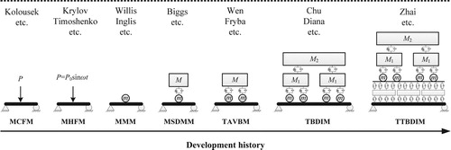
With the deep research into train–bridge interaction, a limitation of the traditional TBDI model is gradually realised by scholars and engineers, that is the influence of track vibrations on the train–bridge system is not considered. As a matter of fact, trains operate on the track structures; and track structures are laid on bridge decks. Therefore, the train, the track and the bridge essentially form an integrated dynamic system, in which the train and the track are coupled by the wheel–rail interactive relationship, and the track and the bridge are linked through the track–bridge interaction. In other word, the track ties the train and the bridge together. Moreover, numerous types of track structures are adopted worldwide. When trains running on different track structures, the wheel–rail forces are different, resulting in different vibrations for different tracks, which will finally influence the vibration of bridges through the track–bridge interaction and vice versa. Therefore, incorporating a detailed track model into the TBDIM is of great necessities. Based on this concept, Zhai et al started to investigate the train–track–bridge system dynamics in 1995, which is an extension of the vehicle–track coupled dynamics [Citation18]. In 1997, they established a train–track–bridge dynamic interaction model (TTBDIM) by including a detailed track model [Citation19]. The evolution of the train–bridge interaction model is illustrated in Figure , in which, P is the moving load, M and m represent sprung mass and unsprung mass, M1 and M2 denote the mass of the bogie and the carbody. It should be noted that the train model and vehicle model can be both established employing TTBDIM, nevertheless, the vehicle model is illustrated in this figure due to the limited space. In the model reviewed in this paper, the train is running at a constant speed if with no specific description. The model could be a two-dimensional model (2D model) or a three-dimensional model (3D model). By means of the 2D model, the responses of the system in the vertical plane could be obtained and through the 3D model, the responses in the vertical and horizontal plane could be obtained.
Figure 1. Evolution of the train–bridge interaction model.
With the rapid development of China's high-speed railway network in the twenty-first century, the dynamic interactions among the train–track–bridge system become severer. As a result, the former Railway Ministry of China in 2001 requested Zhai to lead a coordinated research group with participations from Southwest Jiaotong University, Beijing Jiaotong University, China Academy of Railway Sciences and Central South University to specifically study the high-speed train–track–bridge system dynamics, with the ultimate goal to provide an analytical methodology for simulating train passing bridge at high-speed operation. After a 10-year study, this goal was achieved and the TTBDIM became more and more perfect in this period, which was widely verified and applied in China's railway engineering [Citation20–23].
Meanwhile, based on the idea of integrating the train, the track and the bridge as a coupled dynamic system, many other scholars have also conducted plenty of valuable works. Cheng et al. proposed a type of vehicle–track–bridge element to investigate the 2D interaction of the coupled system in 2001. In the established element, the vehicle is modelled as a mass–spring–damper system, while the rail and the bridge deck are all modelled as beam elements [Citation24]. To analyse the dynamic performance of the train and the bridge, Wu and Yang built a vehicle–rail–bridge interaction model and three types of vehicle–rail interaction elements based on dynamic condensation method [Citation25]. In 2005, a 2D TTBDIM was established by employing the substructure technology by Biondi et al., which was used to investigate the dynamic responses of multi-span simply supported girder bridges [Citation26]. Then in 2007, a vertical TTBDIM was established by Lou, in which the train was modelled as a mass–spring–damper system while the rail and the bridge were simulated as Bernoulli–Euler beam elements [Citation27]. To control the vibrations in the train–track–bridge system, Ziyaeifar proposed a mathematical model with the capability of representing supplementary vibrational control devices adopting tuned mass dampers, and a non-classical incremental eigen analysis was then proposed to explore the system behaviour [Citation28]. In 2009, based on the theory of energy random analysis, Xiang and Zeng [Citation29] established the vibration equations of the train–track–bridge system, and then investigated the mechanism of train derailment on bridge by applying the system dynamics stability concepts. In 2010, Martínez-Rodrigo developed a programme named DYNARET to study the transverse vibrations of railway bridges under resonant conditions [Citation30]. By simulating the ballasted track structure with FEM, Rigueiro et al. presented an investigation of the dynamic response of medium span railway viaducts by considering the influence of the ballasted track [Citation31]. To investigate the low-frequency noise, a TTBDIM was built based on the FEM by Li et al., adopting which various characteristics of the concrete bridge-borne low-frequency noise were obtained [Citation32]. Meanwhile, by creating a 3D rail–ballast–beam finite element model, a 3D TTBDIM was established by Guo et al. [Citation33]. With the established model, the dynamic responses of a bridge subjected to an Italian high-speed ETR500Y train were investigated. Then in 2015, assuming track irregularities to be fully coherent random excitations with the time lags between different wheels and seismic accelerations to be uniformly modulated, non-stationary random excitations with the time lags between different foundations, Zeng et al. [Citation34] investigated the random vibrations of a high-speed train traversing on a continuous slab track bridge subjected to track irregularities and travelling seismic waves by using the pseudo-excitation method. In 2016, Yang and Hwang proposed a TTBDIM based on the direct stiffness method and the mode superposition method [Citation35]. Zhu et al. [Citation36] proposed a hybrid solution to solve the TTBDIM, which was compared with existing technologies. Moreover, the parameters in time-varying train–track–bridge system are inevitably subjected to uncertainty, leading to variability in its dynamic responses. Aiming at this issue, Wan and Ni [Citation37] provided an investigation on how uncertainty in the parameters influences the dynamic responses of time-varying train–track–bridge system employing dynamic sensitivity analysis in the context of a stochastic dynamic system in 2019. Meanwhile, adopting Zhai's TTBDIM [Citation22], Chen et al. and Ling et al. investigated the influence of pier settlement [Citation38,Citation39], seismic effect [Citation40] and derailment impacts [Citation41] on the train–track–bridge dynamic system, respectively. The existing studies have promoted the development of TTBDIM and also proposed many valuable suggestions to actual railway engineering.
Considering the vibrations of track structures, the traditional train–bridge interaction model has been extended to the train–track–bridge dynamic interaction model. As seen in Table , the TTBDIM can be utilised in an extremely wide range, from the basic issues to the application in the research field of train–track–bridge dynamic interaction. On this basis, this paper presents a state-of-the-art review of train–track–bridge dynamic interaction in detail. Primarily, the theoretical modelling method of train–track–bridge dynamic interaction is clearly described in Section 2. Then, the experimental investigation and actual application of train–track–bridge dynamic interaction are presented in Section 3 and Section 4 respectively. Finally, concluding remarks are summarised and some feasible future research works are proposed in Section 5.
Table 1. Research topic of TTBDIM.
2. Theoretical modelling of train–track–bridge dynamic interaction
When a train passes a bridge, the train will induce vibration of the bridge and bring dynamic impact to the bridge structure, which can in reverse influence the running safety and the ride comfort of the train travelling on the bridge. Obviously, the train and the bridge are essentially coupled with each other.
The train and bridge structure dynamically interact by virtue of the wheel–rail interaction as well as the track–bridge interaction. On the one hand, dynamic loads of vehicles are exerted on the rail, and transmitted downward to sleepers (or track slabs) via fasteners, and eventually delivered to the bridge deck. As a result, vibrations of track and bridge are induced. On the other hand, the vibration and deformation of the bridge affect the vibration of the track structure via the track–bridge interface, which causes the changes of the wheel–rail contact geometry and wheel–rail interactive forces. Once the wheel–rail forces vary, the dynamic behaviour of the train system will be affected. From the mechanism in the above two dynamic processes, it could be concluded that the train, the track and the bridge interact alternately and deeply, as shown in Figure . With the increase of train speed, the dynamic interactions of the train, the track and the bridge aggravate. Severe dynamic interactions will not only affect the running safety and the ride comfort of the train passing through the bridge but also have a direct influence on the bridge vibration. Therefore, it is necessary to extend the study of the train–bridge dynamic interaction into the investigation of the train–track–bridge interaction to be able to get a better understanding of the dynamic performance of the entire system.
Figure 2. Train–track–bridge dynamic interaction model [Citation22].
![Figure 2. Train–track–bridge dynamic interaction model [Citation22].](/cms/asset/16bac753-0521-49b7-87a7-a0289b9d1e73/nvsd_a_1605085_f0002_ob.jpg)
Figure illustrates the major elements and their relationships involving in the train–track–bridge dynamic interactions [Citation22]. The entire system consists of three subsystems namely the train subsystem, the track subsystem and the bridge subsystem, which are coupled through the wheel–rail interaction and the track–bridge interaction, respectively. Under possible excitations such as track irregularities, non-round wheels and environmental wind loads, the train–track–bridge coupled system generate dynamic responses, including vehicle vibration responses, bridge structure dynamic responses, track vibration responses and wheel–rail dynamic forces, etc.
Figure 3. Elements of train–track–bridge dynamic interaction [Citation22].
![Figure 3. Elements of train–track–bridge dynamic interaction [Citation22].](/cms/asset/0da23d53-0d4e-46e4-83f9-fc87ffc9d2d2/nvsd_a_1605085_f0003_oc.jpg)
In this chapter, an overview is given of the rich literature on the theoretical modelling methods of the train–track–bridge dynamic interaction system and its major components. The literature about the theoretical methods for the key subsystems including the train, the track, the bridge, the dynamic interaction between these components, the system excitations and the numerical solution is presented.
2.1. Train modelling method in TTBDIM
In the development history of TTBDIM, several types of train model were proposed with different complexity in the railway vehicle dynamics. As shown in Figure , these models include the moving force model (moving constant force model and moving harmonic force model), the moving mass model and the moving vehicle system model [Citation10,Citation42,Citation43].
The moving force model was formulated based on the assumption of the inertia of the moving train load to be small compared to the inertia of the bridge [Citation3–5]. The moving force model is the simplest ‘train–bridge interaction’ model, so it has the advantages of fast calculation and easy to use. However, the moving force model is only suitable to investigate the dynamic response and strength of railway bridge because the dynamic behaviors of moving trains are not considered. The moving mass model was extended from the moving force model by considering the inertia of the bridge and the dynamic interaction between the bridge and the train [Citation7]. Because the suspension systems of the trains are not included, the moving mass model still cannot simulate the dynamic behaviour of trains running on bridges and the train dynamic effects on bridge response. The moving vehicle system model introduces the vehicle mass and suspension system [Citation8–11,Citation13–17,Citation20,Citation21] and thus represents a TBDI formulation. There exist a number of moving vehicle system models for the study of TBDI according to the complexity in the vehicle model. The simplest model within the family of moving vehicle system models is the sprung mass model. The moving vehicle system models considering two axles of a vehicle, a whole vehicle and a series of vehicles have been reported for different concerns [Citation8–17,Citation20,Citation21,Citation42,Citation44,Citation45].
In general, the moving vehicle system models are established based on the theory of MBD, which implies that most of the vehicle degrees of freedom, or equations of motion, are assigned to the motions of the vehicle bodies [Citation22,Citation46]. A comprehensive literature review of railway vehicle MBD modelling is provided in [Citation46–48]. Here the main focus is placed on MBD approaches for vehicle dynamics simulations in TTBDIM. With respect to the complexity of the railway vehicle model in TTBDIM, the DOFs of the vehicle model can range from several to dozens according to the issue of interest [Citation10,Citation22,Citation42,Citation49–51]. The vertical TTBDIM usually include several DOFs that related to the vertical and pitch motions of the railway vehicle system [Citation20,Citation52]. In the vertical TTBDIM presented by Vu-Quoc and Olsson [Citation53], the longitudinal DOFs of the vehicle components were also included to simulate the speed variation of the train crossing the bridge. The vertical-lateral or 3D TTBDIM are widely applied with the fast development of computer technology [Citation20,Citation22,Citation42,Citation49,Citation50]. These models fully consider the 3D coupling behaviour between railway vehicle components via bogie suspensions.
A typical multi-body moving vehicle system model [Citation22,Citation51] is shown in Figure . The 3D vehicle model consists of seven rigid bodies, including the carbody, bogies and wheelsets. The model completely considers the linear or nonlinear stiffness and damping properties of the primary and the secondary suspensions in three directions, e.g. nonlinear yaw dampers and secondary lateral bump-stop clearances, etc. [Citation54]. Five DOFs are taken into consideration for each rigid body, describing vertical, lateral, roll, yaw and pitch motions.
Figure 4. A three-dimensional vehicle model in TTBDIM:(a) end view of the model [Citation22]; (b) nonlinear characteristic of the yaw damper; (c) nonlinear characteristic of the secondary lateral bump-stop [Citation54].
![Figure 4. A three-dimensional vehicle model in TTBDIM:(a) end view of the model [Citation22]; (b) nonlinear characteristic of the yaw damper; (c) nonlinear characteristic of the secondary lateral bump-stop [Citation54].](/cms/asset/b7592dd2-bc32-4a39-bc23-605b0425562d/nvsd_a_1605085_f0004_ob.jpg)
It's worth noting that such a model is capable of simulating the 3D dynamic response of railway vehicles travelling on bridges, as well as evaluating the ride comfort and running safety of the train. This model can, of course, be further extended to the 3D TTBDIM by considering the longitudinal DOFs of the vehicle components. An example has been shown by Ling et al. [Citation41], in which the rigid bodies of the locomotive and wagon were assigned with six DOFs.
One issue should be noted for the train model in TTBDIM is the solution of the nonlinear components. There are a few important nonlinear elements in the railway vehicle dynamics system including the wheel–rail contact and suspension components. To some extent, the accuracy of rail vehicle multi-body models is mainly affected by the model of wheel–rail contact and by the models of vehicle suspension components [Citation55,Citation56]. This is especially true regarding the high-speed trains equipped with a lot of hydraulic dampers and freight wagons with friction elements [Citation22,Citation50,Citation57,Citation58]. However, these nonlinearities are rarely considered in the reported TBDIMs and TTBDIMs. In Ref. [Citation22,Citation50], several important nonlinear elements existing in the suspension systems of a high-speed railway vehicle was adopted in the 3D TTBDIM by Zhai et al. The saturation nonlinearity of the hydraulic yaw dampers was modelled as shown in Figure (b), while the nonlinear model of the secondary lateral bump-stop is presented in Figure (c). Ref. [Citation59] presented an example of considering the nonlinear characteristics of friction elements in freight wagon dynamics. For a three-piece bogie comprising one bolster and two side frames, there are no spring and no viscous damping component in the primary suspensions. The side frames directly contact with the wheel axles in the vertical direction. There are longitudinal clearances δx and lateral clearance δy between the axle box and the side frame, see Figure (a). In consideration of the combination effect of the Coulomb friction and the clearances between the axle box and the side frame, the nonlinear force-displacement characteristics in these places can be described in Figure (b,c).
Figure 5. Modelling of the axle box connection between side frame and wheelset [Citation60]: (a) clearances in axle box, (b) longitudinal force characteristic, and (c) Lateral force characteristic.
![Figure 5. Modelling of the axle box connection between side frame and wheelset [Citation60]: (a) clearances in axle box, (b) longitudinal force characteristic, and (c) Lateral force characteristic.](/cms/asset/9342fbf5-32ff-46be-a529-0aaca5177279/nvsd_a_1605085_f0005_oc.jpg)
Another issue raised for vehicle modelling in TTBDIM is the effects of structural flexibility. It is well known that the structural flexibility of the vehicle components especially the carbody has important effects on the dynamic response and ride comfort of railway vehicles. Recently, a few papers [Citation60–63] investigated the effects of carbody flexibility on the train–bridge interaction. In these studies, the train carriages were simplified as free Euler beams supported by bogie suspensions that introduced into the TBDIMs. The general conclusion is that the flexible vibration of carriages has no practical influence on the bridge response, while a great influence on the vehicle response and the ride comfort of trains travelling on bridges.
2.2. Track modelling method in TTBDIM
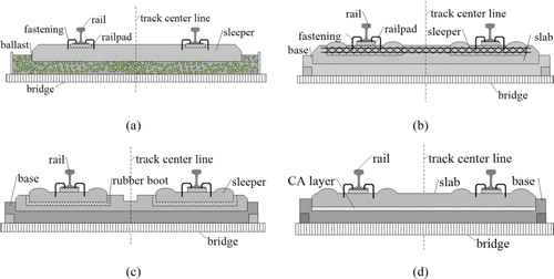
The railway track is a key structure guiding the train and distributing the load to the bridge structure or embankment. Although the ballasted track is widely used around the world, a large variety of non-ballasted track structures with different components has been developed to meet the requirements of different railway transportation systems. Therefore, rail bridges can contain either the ballasted track or the non-ballasted tracks. Figure shows the schematics of a conventional ballasted track and three typical non-ballasted tracks built in China. The ballasted track system (Figure (a)) consists of rail, railpad and fastening, sleeper and ballast. The type ‘Double-block’ track (Figure (b)) consists of rail, fastening and railpad, concrete sleeper, concrete slab and concrete base. The rails are fastened onto sleepers in two blocks, which are directly concreted into a cast-in-place slab. There is no elasticity between the slab and the concrete base or bridge deck. Thus, only the vibration of rails is important for train–track interaction for this type of non-ballasted track. The type ‘Elastic-supporting-block’ track (Figure (c)) consists of rail, fastening and railpad, concrete block, block pad and rubber boot and concrete base. The track system elasticity existing in the fastening system and the rubber boot, which leads to that the vibrations of rails and concrete blocks are both momentous for the train–track interaction. The slab tracks (Figure (d)) are widely used in high-speed railways, which consists of rail, fastening and railpad, concrete slab, CAM layer and concrete base. The slab elastic bearings separate the track from the bridge deck, thus constituting a floating slab track. Both the vibrations of the rails and slabs have significant effects on the train–track interaction.
Figure 6. Typical track structures on bridges: (a) ballasted track, (b) double-block track, (c) elastic-supporting-block track, and (d) slab track.
It is obvious that these different tracks laid on railway bridges have different structural and material properties and therefore have different dynamic behaviours. However, the elastic and dynamic effects of the track structure are not always taken into account in traditional bridge dynamic assessments [Citation10,Citation22,Citation42,Citation49–51]. It is well known that the track dynamic behaviour has a significant effect on train running safety and ride comfort [Citation46–48,Citation51]. It is also reported that the overall stiffness and the dynamic response of bridges under moving trains have both been shown to be sensitive to the changes in track stiffness, especially for short-span bridges [Citation43]. Therefore, a detailed track model considering the elastic and dynamic effects of track structure is a necessary condition for the accurate analysis of the TTBDIs.
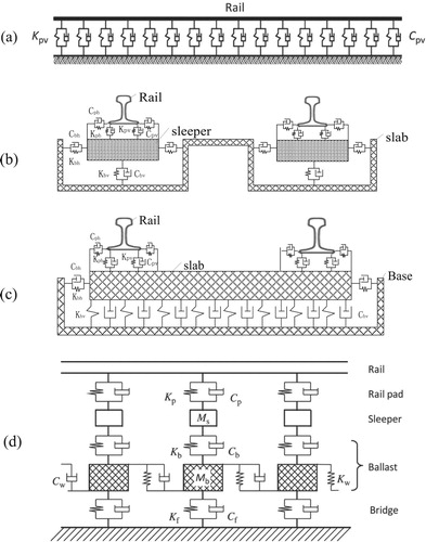
A survey of track dynamic modelling methods for train–track interaction can be found in [Citation46–48,Citation51,Citation64]. The reported track system models for analysis of TTBDIs can be grouped into three categories, namely: (i) lumped parameter models; (ii) continuous beam models; and (iii) discrete beam models. The lumped parameter model is the simplest model that includes rigid mass or massless elements for rails supported on sleepers and/or ballasts connected by spring and damping elements [Citation46–48,Citation64]. In continuous models, the rails are usually represented by infinite Euler or Timoshenko beams resting on Winkler elastic foundations [Citation46–48] or discrete sleepers along the track [Citation22,Citation42,Citation46–48,Citation64]. Discrete models usually include finite rails modelled using the finite element (FE) method [Citation26,Citation43,Citation46–48,Citation65–67]. In FE modelling, two classes of track models can be distinguished: mass–spring–dashpot models (with the rails as beam elements) [Citation31,Citation33,Citation43,Citation68] and solid models (which may also include beams and rigid bodies) [Citation32,Citation43]. A mixture of the two FE approaches has also been applied in TTBDIM [Citation43,Citation69]. The lumped parameter models cannot simulate the dynamic response of the track structure [Citation46,Citation64]. The continuous and discrete beam models can provide more accurate predictions of the behaviour of all the track components, including the rails, the fastenings, the sleepers, the slabs and even the ballast [Citation43,Citation46,Citation64,Citation70].
The number of layers of the track models in TTBDIM can be one up to four. The single-layer track model (Figure ) usually includes a finite/infinite rail beam laid on the bridge [Citation24,Citation26,Citation65]. Such a model can be used to represent the track system with a high elastic fastening that separates the rails from the track base that being precast into the bridge deck. For the double-block non-ballasted track shown in Figure (b), the single-layer model is considered to represent the dynamic behaviour of the track system fairly. If the track components like sleepers and track slabs sustaining the rails that also have important effects on the track system dynamic behaviour, a two-layer model including rail and sleeper/slab masses is further needed. To simulate the dynamic effects of the elastic-supporting-block track system (Figure (c)) and the non-ballasted slab track system (Figure (d)), the two-layer track model should be justified and efficient. In the two-layer track models [Citation31–33,Citation68], the concrete sleepers or blocks are usually modelled as rigid bodies, while the elastic bearing layers connecting the bridge deck and these rigid bodies can be simplified as linear or nonlinear viscoelastic elements. The track slabs can be assumed as finite length beams in 2D models, while described as elastic rectangle plates supported on the viscoelastic foundation in 3D models [Citation22,Citation51,Citation54]. The three-layer or four-layer track models are mainly developed for the ballasted track system, which consists of rails, sleepers, ballast and/or subgrade. In the three-layer or multi-layer track models, the ballast and subgrade layers beneath the sleepers are usually treated as uniformly distributed equivalent mass elements that connected with each other [Citation22,Citation43,Citation46,Citation64]. For example, a five-parameter model of the ballast block under each rail supporting point is adopted in [Citation22,Citation51,Citation54], which is formulated based on the hypothesis that the load-transmission from a sleeper to the ballast approximately coincides with the cone distribution [Citation71].
Figure 7. Typical track models with increasing complexity (a)–(d): (a) single-layer model, (b) two-layer model for elastic-supporting-block track, (c) two-layer model for slab track, and (d) multi-layer model for ballasted track.
Some comparative studies on the ballasted track models with different layers have been reported in the literature [Citation24,Citation26,Citation31,Citation43,Citation64]. The general conclusion from these studies is that the track model has little influence on the bridge response, while a larger influence on the vehicle response and the wheel–rail contact forces. Rigueiro et al. [Citation31] compared three ballasted track models with one to three-layer on three slab bridges with span lengths in the range 11–24 m. Only small differences in bridge deck acceleration were found in the frequency range 0–15 Hz between these track models. But above 15 Hz, the track models were found to act as filters, reducing the high-frequency vibrations. It should be noted that a variety of defects (such as rail joint, rail corrugation, wheel flat, wheel round, void sleeper) existing at the wheel–rail interface or external impacts (such as crosswind, earthquake, vehicle collision) can raise the high-frequency vibration of the train–track–bridge system. For these complex service conditions, a detailed ballasted or non-ballasted track model should be considered.
At last, it is believed that the bridge frequency will decrease while its vibration amplitude will increase if the nonlinear characteristics of the track components like pads and ballast are included [Citation43,Citation72,Citation73]. However, almost all the current track models in the reported TTBDIMs are linear as the consideration of the track nonlinearities is still an open problem for most types of track models. Such a consideration seems to be impossible for the models in the frequency domain [Citation46–48]. By introducing some newer time-domain models raised in train–track interaction, the TTBDIMs taking into account those nonlinearities become available, which needs further study.
2.3. Bridge modelling method in TTBDIM
For the modelling of bridge in TTBDIM, two main approaches including the analytical method and the finite element method (FEM) have been widely used. Research on the vibration of bridges by using analytical or semi-analytical approaches is abundant. In these studies, the analytical or semi-analytical models for bridges are established based on the beam theories. A beam that is simply supported at both ends is the most popular structure that has ever been adopted in the study of vehicle-bridge interaction [Citation3–5,Citation42,Citation43]. Timoshenko [Citation5] derived an enormous number of approximate solutions to the problem of simple beams under moving loads. Similar models were adopted by Vellozzi [Citation74] in studying the vibration of suspension bridges. Zhai et al. [Citation20] formulated a semi-analytical bridge model for studying the vertical train–track–bridge interaction. In their model, the bridges were described as simply supported Bernoulli–Euler beams, while the differential equations of the beams were solved by using the modal superposition method [Citation51,Citation64]. The analytical methods have the advantage of high computation efficacy and easy to use, but it is impossible to represent the complicated bridge structures accuracy using these simplified models.
With the advent of computers with high performances, various numerical methods become a highly effective tool for simulating train–bridge coupling vibration, playing an important role in this field, which are used by more and more researchers. The commonly used numerical simulation methods include the FEM, the BEM (boundary element method) and the F–B hybrid method [Citation42,Citation43,Citation50,Citation51]. Owing to its high accuracy and versatility, the FEM is extensively used to formulate the bridge models in TTBDIM. For different types of bridge structures, the spatial beam element, the spatial pole element, the plate/shell element and other special elements can be used for modelling of specific components. The simply supported bridge can be easily modelled by 3D beam elements [Citation22,Citation42,Citation43,Citation50,Citation51], while the FE models for the huge complicated bridges usually consist of a mixture of the spatial beam element, the spatial pole element, the plate element and other special elements [Citation22,Citation42,Citation43,Citation50,Citation51,Citation75]. The direct integration approaches are widely adopted to solve the equations of the bridge FE models with arbitrary bridge geometry, in which the choice of time step and numerical damping parameters affect the solution [Citation43]. The limitation of the direct integration for the complicated bridge FE models is very time-consuming due to the large number of DOFs. Therefore, some approximation assumptions such as the modal superposition method have been adopted in the FE modelling of the complicated huge bridges [Citation50,Citation51]. A lot of recent researches used these simplified approaches rather than the full FEM to deal with the dynamic analysis of train–track–bridge systems [Citation50,Citation51]. But it should be recognised that the chosen modes in these approximation assumptions provide an automatic cut-off of higher frequencies, which may have a significant effect on the acceleration response [Citation43].
2.4. Modelling method of dynamic interaction between subsystems in TTBDIM
2.4.1. Wheel–rail dynamic interaction model
The wheel–rail dynamic interaction model is an essential element that couples the train subsystem with the track subsystem at the wheel–rail interfaces. The wheel–rail contact model addresses two basic issues: the geometric relationship and the contact forces between the wheel and the rail. When dealing with the geometric problem of wheel–rail contact system, the ‘no loss of contact’ or ‘rigid contact’ assumption that the displacement of a wheel is always equal to that of the bridge/rail beam under the wheel has been often adopted in the conventional train–bridge dynamic interaction analyses [Citation22,Citation25,Citation50,Citation51,Citation76,Citation77]. Such a simplified model neglects the nonlinear geometric relationships of wheel–rail contact due to the curved wheel/rail profiles, the nonlinear characteristics of wheel/rail materials and the no loss of contact. In fact, the track structure laid on the bridge is an elastic-damping system. On account of the wheel load-induced vertical and lateral vibrations and deformations of the track structure, the displacements of the wheel and the underneath bridge are unequal. On the other hand, when a rail vehicle moves on an irregular track, three types of wheel–rail contact states are possible (see Figure ). Addition to the constant contact under normal conditions (Figure (a)), the instantaneous loss of contact between one side wheel of a wheelset and the rail would appear (Figure (b)), and loss of contact at both sides of the wheelset (Figure (c)) could also happen in some particular conditions [Citation22,Citation51].
Figure 8. Wheel–rail contact states: (a) constant contact, (b) instantaneous loss of contact at one side, and (c) loss of contact at two sides [Citation24].
![Figure 8. Wheel–rail contact states: (a) constant contact, (b) instantaneous loss of contact at one side, and (c) loss of contact at two sides [Citation24].](/cms/asset/ff521136-8d6a-4e2c-a468-c77da17d5cf7/nvsd_a_1605085_f0008_ob.jpg)
To consider these important nonlinear characteristics of wheel/rail geometric contact, a nonlinear wheel–rail spatially dynamic coupling model was firstly introduced into the TTBDIM by Zhai et al. [Citation22,Citation51]. Recently, some similar nonlinear models allowing for the loss and subsequent re-establishment of wheel–rail contact were reported in Ref. [Citation32,Citation79,Citation79]. The improved model is capable of considering three kinds of rail motions in vertical, lateral and torsional directions and dealing with the situation that the wheel loses its contact with the rail. The wheel/rail nonlinear contact relationship due to the curved and worn wheel/rail profiles is included as well.
The wheel–rail contact forces include the normal contact force and the tangent creep forces. The nonlinear Hertzian elastic contact theory is usually used to calculate the wheel–rail normal contact forces [Citation22,Citation51]. For lateral dynamics analyses of the train–track–bridge system, such as train running stability and safety under crosswinds or earthquakes, advanced contact theories like the Kalker linear or nonlinear creep theories should be adopted. For the calculation of wheel–rail nonlinear creep forces, the Kalker's 3D exact theory (CONTACT) is currently considered the ‘golden standard’ for wheel–rail contact evaluation. Some recent works show that the 3D finite element method (FEM) can also solve the 3D wheel/rail contact characteristics close to the CONTACT [Citation80–82]. But these two exact models are only suitable for one wheel/rail rolling contact simulation due to the very expensive computation cost at the current stage. Thus, some approximate models, such as the FASTSIM, USETAB, Vermeulen–Johnson, Shen–Hedrick–Elkins, Polach methods, are commonly used for fast calculation applications of the train–track–bridge dynamic simulations [Citation23,Citation32,Citation78,Citation79,Citation83–85].
It is noted that the linear creep theory by Kalker that widely used in TTBDIMs is only available for small creepage, where no slip occurs at the wheel–rail interface, and the creepages are in the region of adhesion [Citation64]. But when the creepages are in the regions of creep and slip, large creepages appear in the wheel–rail contact patches and the relationship between the creep forces and creepages are nonlinear. In such a situation, the linear creep force model is not suitable. The nonlinear models such as the Shen–Hedrick–Elkins model [Citation86] or the Kalker FASTSIM algorithm [Citation87] should be applied to the calculation of the creep forces of the wheel and the rail under the large and small creepages.
Antolín et al. [Citation79] compared different wheel–rail contact algorithms and demonstrated that differences arise mainly in the lateral response of the vehicle and the lateral wheel–rail forces. Due to the unsprung wheel mass, slightly higher vertical bridge deck accelerations are obtained with a rigid contact assumption than with Hertzian contact in the presence of track irregularities. This kind of comparisons should be also performed for different wheel–rail creep force models, the train–track–bridge system subjected to earthquakes and crosswinds and the high pier and curved bridges, where the lateral interaction are the main concern.
2.4.2. Track–bridge dynamic interaction model
Track–bridge dynamic interaction models are established to determine the track–bridge interaction forces. For the bridges containing ballasted tracks, the train loads are transmitted to the bridge deck through the ballast layers. While for the non-ballasted tracks, an elastic bearing layer (such as CAM and/or rubber pads) is often designed to connect the track slabs and the bridge decks. In the ballasted or non-ballasted track–bridge dynamic interaction models, the track–bridge interaction can be discretized into a series of point-to-point interactions which are connected with linear spring and damping at each contact point [Citation22,Citation51].
An example of a slab track–bridge dynamic interaction model is shown in Figure , in which the connection between the track slab and the bridge deck is treated as linear spring and damping element. As shown in Figure , the lateral track–bridge interaction forces FsHi at the ith support section and the vertical track–bridge interaction forces FsVij at the jth support point can be calculated by:
(1)
(1)
where Ksh and Csh represent the lateral stiffness and damping of track slab, respectively; Ksv and Csv denote the stiffness and damping of elastic layer under the track slab including the CAM and/or the rubber pad; ysi is the lateral displacement of the slab; zsij is the vertical displacement of the slab at the jth support point; and xsij represents the lateral distance between the bridge section centroid and the jth support point of the ith support section under the slab.
Figure 9. Slab track–bridge dynamic interaction model [Citation22].
![Figure 9. Slab track–bridge dynamic interaction model [Citation22].](/cms/asset/fe434f79-812b-4992-91f2-1cc3f5bf1890/nvsd_a_1605085_f0009_ob.jpg)
2.5. Description of system excitations in TTBDIM
There is a variety of excitation sources that generating the vibration of the TTBDI system. The important excitation sources are summarised in Table , which includes the geometry defects at the wheel–rail interface, the bridge deformations due to the pier settlement and temperature variation, and the external impact loads such as crosswind, earthquake, vessel/car collision, etc.
Table 2. Main excitation sources in TTBDI system.
Track irregularities are the most important excitation source for the TTBDI system. The track spectrums described by power spectral density (PSD) functions of the track geometry quality are commonly used to generate the random track irregularities. Various PSD functions generally derived from field measurements are used by different railway authorities. The commonly used PSD functions in the TTBDI research field include the Federal Railroad Administration (FRA) spectrum [Citation42,Citation51,Citation64], the German track spectrum [Citation10,Citation42,Citation51,Citation64], the SNCF track spectrum [Citation10,Citation43,Citation88], the Chinese track spectrum [Citation22,Citation51,Citation64,Citation89] and PSD functions proposed by ISO 3095 [Citation90,Citation91]. For time-domain analyses, realisations of the PSD functions are obtained by performing inverse Fourier transforms with random phases. Detailed explanations on how to generate profile realizations from a PSD can be found in Zhai and Xia [Citation51], Zhai [Citation64], Claus and Schiehlen [Citation92], Dinh et al. [Citation78]. Measured track irregularities, as used in Ref. [Citation77,Citation102], for example, are another relevant way of including random track irregularities. Unfortunately, these data are obviously not available in the design phase.
The uneven geometry or defect at wheel–rail interfaces is another important excitation source for the vibration of the TTBDI system. The wheel–rail defects usually generate sharp peak responses to the TTBDI system. Some defects cause periodic excitation whilst others cause non-periodic or localised excitation defined as impulse excitation. The periodic defects include the rail corrugations, the out-of-round wheels or the rounded flat wheels, and the non-periodic defects include the indentation on the railhead due to the spalling, the squats or the defect of welded-rail and dipped-rail joints. So, it is a normal practice to model the periodic defects by harmonic waves such as cosine functions represented in Ref. [Citation51,Citation64]. These periodic geometry defects are treated as an addition to the elastic compression at the wheel–rail contact zones. On the other hand, the localised geometry defects can be represented by cosine displacements [Citation41,Citation51,Citation64] or the impact velocities [Citation51,Citation64] to the wheels passing through the defective rails.
The external impact sources such as crosswind, earthquake, vessel/car collision threat the running safety of trains travelling on bridges, which is the main concern of the analysis of the TTBDI system. It is a common practice to introduce the time series of turbulent wind velocity into the TTBDIM when the dynamic responses of the train–track–bridge system subjected to crosswinds are investigated [Citation42,Citation50,Citation51,Citation94–97]. As the measured velocity profiles of natural crosswinds are always scarce, the artificial wind velocity time series is often adopted as the input [Citation50,Citation51]. To ensure the rationality of simulation results, the property of the artificial wind velocity should be close to that of the natural crosswinds as much as possible. There are four common approaches available to simulate a stochastic wind velocity field, including the spectral representation method, linear filtering method, the wavelet method and the artificial wind field based on observed records [Citation50]. It should be noted that it is important not only to reproduce the spectral components of wind velocity, but also the correlation of the time histories describing wind velocity at different locations along the span and at different heights.
When the dynamic response of a train–track–bridge system subjected to an earthquake is studied, the time histories of the seismic motions around the bridge piers are essential. The seismic ground motion for the analysis of TTBDI can be obtained from strong seismic motion records [Citation17,Citation40,Citation42,Citation98,Citation101], which are usually rare and insufficient. As a result, the application of artificial ground motions generated by numerical simulations is a good option. The seismic ground motion is a typical non-stationary process, and the motion samples can be obtained by using the random field theory based on spectral method [Citation50,Citation100,Citation101]. Two numerical methods namely the unconditional and conditional simulations have been widely used to obtain the random field of seismic ground motion [Citation50]. Besides, if a long bridge is considered, the effects of the spatial variation of the seismic ground motion should be considered.
The collision loads on bridge structure concerned in the dynamic analysis of TTBDI mainly include the impacts due to vessel collision, vehicle collision and ice-floe collision [Citation50,Citation102,Citation103]. These collision loads are very complicated, with their respective characteristics in the time history, the maximum impact force and the acting position. The impact forces on bridge formed during the collision process are also influenced by the mass and velocity of the moving object, the contact area, location and angle of collision, the deformation stiffness of the colliding object itself and the collided structure, and the boundary conditions. Some of the collision loads adopted in TTBDIM are achieved by field tests [Citation102,Citation104], while most of the vessel, vehicle and ice-floe collision loads are obtained by FE simulation due to the high cost-effective [Citation50,Citation105–108].
The bridge structural deformations due to the pier settlement and temperature variation are also important excitations to the TTBDI system, which can be modelled as additional displacements to the bridge pier or deck in the simulations [Citation38,Citation39,Citation50,Citation108].
2.6. Numerical solution method
The train–track–bridge dynamic interaction system has a large number of DOFs and strong nonlinearities arising from the wheel–rail contact and suspension elements that formulating very complicated mass, damping and stiffness matrices. Therefore, it is crucial to seek a high-efficiency numerical algorithm to solve such a large-scale system. A majority of the methods used in solving the TTBDIMs are time-domain-based due to its strong capacity to solve the nonlinear problems [Citation42,Citation43,Citation50,Citation109–112]. Frequency domain methods with high computational efficiency have also been presented by Green and Cebon [Citation15] and Lombaert and Conte [Citation113].
To solve the equations of the TTBDIM in the time domain, a time stepping integration solution of the train, the track and the bridge subsystems is widely employed. Commonly adopted time integration schemes include the Newmark method [Citation110], the HHT-α method [Citation111], the Wilson method [Citation112] and the Zhai method [Citation109]. To achieve maximum computational efficiency, many methods are specialised for a specific problem, often including analytically derived equations of motion for the vehicle and track subsystems and an FE representation of the bridge subsystem. The explicit time integration schemes for the vehicle and track subsystems are very popular considering the high time-dependent nonlinearities. On the other hand, the bridge FE models are usually solved by using the implicit integration scheme to achieve fast calculation. Therefore, a hybrid explicit–implicit integration scheme was proposed by Zhai et al [Citation22,Citation51] for the TTBDIM. In Ref. [Citation22], a simple fast explicit two-step integration method namely ‘Zhai method’ was adopted to solve the train–track system dynamics, while the Newmark-β implicit integration method was employed for analysis of the bridge structure dynamics. It has been proved that the Zhai method is very efficient for dynamic analyses of the vehicle–track coupled system with strong nonlinearities, and the Newmark-β method is suitable for complex structure dynamics analysis. Numerical integration processes for the train–track system and for the bridge system can be harmonised through the track–bridge interaction. The practical calculation has shown the effectiveness of the hybrid explicit–implicit scheme.
The basic principle of Zhai's explicit two-step method is as follows: the displacements and velocities of a system at next time step can be estimated based on the dynamic responses at previous two steps
, and the accelerations at time step
are calculated from the equations of motion. The integration scheme to calculate the displacement and the velocity of a system is expressed as [Citation109]:
(2)
(2)
where
,
and
are the generalised displacement, velocity and acceleration of the system, respectively; Δt is the time step; ϕ and ψ are free parameters that control the stability and numerical dissipation of the algorithm.
3. Experimental investigation of train–track–bridge dynamic interaction
Before the 1960s, the investigation on bridge vibration caused by running train was mainly conducted with experimental technology due to the poor computational devices. From 1907 to 1921, large-scale experiments were performed in America, through which the bridge resonance was found to be mainly caused by the unbalanced hammer force of a steam locomotive, and the concepts of ‘impact coefficient’ and ‘critical speed’ were first proposed [Citation51]. Then in the following 100 years, experimental technology has become an extremely important method to investigate the dynamic responses of the train–track–bridge system. Especially in the twenty-first century, valuable suggestions were proposed through experimental investigation ascribed to the rapid development of sensor technology.
According to the target of test research, three aspects are introduced in the present review work, namely the field tests for validating simulation models, the situ tests for assessing the system operation safety and the experimental investigations for the long-term monitoring of the system performances.
3.1. Field test for validating train–track–bridge dynamic model
Field tests for validating the TTBDIM can be mainly adopted in two aspects: (a) tests for determining parameters required in the models and (b) tests for validating simulation models.
In some cases, the key dynamic parameters used in the models are unclear, and field tests should be further performed to determine these values. In addition, some parameters are different with those in the design stage due to the long-term operation, hence relevant experiments should be conducted to obtain the evolved parameters. For instance, to accurately investigate the responses of the 7-span Sesia viaduct subjected to both ambient vibration and the excitation of Italian ETR500Y high-speed trains, a situ test was carried out to obtain the modal properties of the bridge by Liu et al. [Citation70]. To estimate the mechanical properties to be used for numerical analyses of railway bridges, Rauert et al. [Citation114] performed tests on railway ballast within the framework of the European research project DETAILS (Design for optimal life cycle costs of high-speed railway bridges by enhanced monitoring systems). Besides, Kim et al. [Citation115] and Feng et al. [Citation116] have also obtained key parameters through field tests.
In most cases, the TTBDIMs were built without validations due to the difficulty of performing onsite tests on actual railway lines, resulting in the uncertainty of the established models. Nevertheless, the rest dynamic models were verified with test results to show the capability of accurately simulating the train–track–bridge system. In 2005, Xia and Zhang proposed a computational model for a train–bridge system, which was validated by the test results of the China-Star high-speed train running through a bridge with 24 m-span PC box girders on the Qin-Shen Special Passenger Railway in China [Citation77]. Over the following years, Su et al. [Citation76], Guo et al. [Citation33], Galvín et al. [Citation117], Chen et al. [Citation38] and Ticona Melo et al. [Citation118] have performed many high-quality field experiments to validate their TTBDIMs.
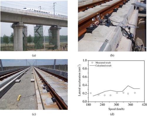
From 29 May to 30 June in 2008, an all-around field experiment was performed on the Beijing–Tianjin intercity railway, the first high-speed railway in China [Citation23]. The tested bridge, Yangcun Bridge, is composed of the 32 m simply supported beams, with CRTS-II slab track. The CRH2 and the CHR3 high-speed EMUs were adopted as the tested trains in the test. The tested train and bridge are shown in Figure (a), and the measurement point arrangement is displayed in Figure (b,c). Further, the acquired test results were adopted to validate the established TTBDIM, as illustrated in Figure (d), which indicates that the established TTBDIM is reliable in exploring the dynamic behaviours of the train–track–bridge system.
Figure 10. Field test on the Yangcun Bridge of the Beijing–Tianjin high-speed railway: (a) test site, (b) arrangement of sensors on the track, (c) arrangement of sensors on the bridge, and (d) an example of the comparison between calculated and measured results.
3.2. Test for assessing safety operation of the train–track–bridge system
With the rapid development of high-speed railway and heavy-haul railway, the influences of faster speed and heavier weight on the running safety and ride comfort of trains travelling on bridges deserve serious concern. Although the theoretical study can be adopted to assess the safety operation in some cases, the accuracy is doubtful due to the facts that (a) the dynamic model is simplified and (b) the parameters used in the calculation are usually different with those in the actual situation. As a consequence, some scholars prefer to evaluate such problems with experimental technology.
In 2003, to investigate the dynamic responses of the Antoing Bridge located on the high-speed railway line between Paris and Brussels subjected to Thalys trains, Xia et al. performed a test by measuring the modal parameters, deflection, acceleration, strain of girder concrete and so on, which can be a reference for the study and the design of high-speed railway bridge [Citation119]. During the next 15 years, plenty of research conducted by Shin et al. [Citation120], Guo et al. [Citation121], Wang et al. [Citation122] and so on, played an important role in assessing the running safety and ride comfort of the train–track–bridge dynamic system. The authors also have done many remarkable works in this field, one of which is illustrated for instance.
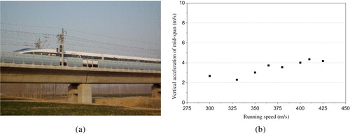
In 2011, an onsite test was performed to assess the operation performance of the Beijing–Shanghai high-speed railway led by the Train-Track Research Institute (TTRI), in which the dynamic behaviours of track and bridge structures were measured. The 32 m-long simply supported girder bridge and CRTS-II slab track were chosen as the test objects. The CRH380A and CRH380B were the test trains, whose test running speed changes from 254 to 425 km/h. Figure shows the basic information and some results of the test. Compared with the relevant values in Chinese codes, the vibrations of the bridge are within the allowable range, indicating that the running safety of this railway can be ensured at high speed.
Figure 11. Field test on the Beijing–Shanghai high-speed railway: (a) test site and (b) an example of test results.
It should be emphasised that a comprehensive experiment should be conducted before the operation of a new-constructed high-speed railway, which is the most important experiment to ensure of the safe operation of the railway. The experiment usually lasts for more than three months. In this test, all the subsystems attached to the new high-speed railway should be tested synchronously, including the high-speed trains, traction power system, communication system, railway subgrade/bridge/tunnel/track structures, dynamic behaviour and vibration-induced noise, passenger service system and so on. Only when all the test results meet the relevant standards, the high-speed railway is then allowed to operate for commercial use.
3.3. Experiment for investigating long-term performance of the train–track–bridge system
Another aspect of the experimental investigation is to explore the long-term performance of the train–track–bridge system, i.e. the evolution of the characteristics and parameters in the system. The longer the service time is, the more degenerate the characteristic of the railway system is, which may influence the safe operation if the performance of the railway line substantially changes. For instance, the time-dependent pier settlement and bearing damage deteriorate the mechanical properties of the train–track–bridge system, which directly influences the track–bridge interaction, and further aggravate the vibrations in the system.
Moreover, the long-term monitoring of the train–track–bridge system guides the state-based maintenance for the track and bridge structures. With the monitored data, the degradation of the structures is easy to be obtained. Then compared with the standards, the reasonable maintenance plan is convenient to be made. Hence, it is very important to monitor the evolution of the property of the train–track–bridge coupled system.
Research on this topic is very hot. Many scholars have reported a lot of method and technology for the long-term monitoring of the train–track–bridge system. From January 2004 to May 2007, Kwark et al. [Citation123] conducted a long-term field test on a high-speed railway bridge under the actual service condition in South Korea and found that some bridge dynamic indicators exceed the standards. On this basis, a vibration control measure was carried out on the bridge to ensure the safety operation of the railway. With fibre Bragg grating sensors, Chan et al. [Citation124] presented an experimental investigation on the Hong Kong's landmark Tsing Ma Bridge, which is a 1377 m-long suspension bridge carrying both railway and regular road traffic. In addition, Ni et al. [Citation125], Cruz and Salgado [Citation126], Leander et al. [Citation127] and Karoumi et al. [Citation128] have also made a contribution to the development of the structural health monitoring technology for the train–track–bridge coupled system. It is believed that, with the rapid development of high-speed railways, the long-term monitoring of the train–track–bridge system will continue being a very valuable research topic in the following decades, which deserves more and more attention worldwide.
4. Application of train–track–bridge dynamic interaction theory
In the past years, with the rapid development of railway transportation, numerous works for extensive application scenarios were performed by worldwide scholars based on TBDI. These research works will be introduced from three perspectives in the following part, namely the dynamic performance evaluation of the train–track–bridge system, the safety assessment of the train–track–bridge system under special excitations, and the investigation of environmental vibration and bridge-borne noise problem.
4.1. Dynamic performance evaluation of the track–bridge system
Performance evaluation of bridge and track by simulations in the design stage has been proved to be a significant way to find out structure design defects from the dynamic perspective, to prevent potential risks in operation and to save time or budget for the design and construction. The key advantage of train–track–bridge dynamics simulation lies in the ability to perform a comprehensive and intensive dynamic analysis of bridge and track structures as well as the running trains.
Early in the design period, the performance evaluations of basic characteristics of structures under operation speed range, such as bridge and track responses as well as bridge resonance characteristics, are essential issues. Such works will be introduced in Section 4.1.1. During long-term service of bridges, structural health problem would inevitably appear due to structure fatigue under repetitive actions of moving vehicles, and it might threaten regular operation of the railway system, therefore evaluations of fatigue life and improvement measures of bridges are concerned issues with the help of TTBDIM, as presented in Section 4.1.2 and Section 4.1.3, respectively. In addition, the uncertain factors objectively existing in the system parameters or the system excitations are usually ignored in conventional works. But in recent years, stochastic approaches for the train–track–bridge dynamic analysis with special concerns on the uncertainties have been proposed in plenty of papers, as reviewed in Section 4.1.4.
4.1.1. Evaluation of basic characteristics of the system
To ensure the operation safety of a railway line, it is an extremely important issue to investigate basic characteristics of bridge and track structures including the dynamics indices under actual operation speed as well as the resonance characteristics.
(i) Dynamic performance of bridge and track under operation condition.
Evaluation of the system dynamic performance under operation condition is an essential issue to reasonably design or maintain a bridge. For example, in China, such evaluations are required for every new-constructed bridge, especially for the important or extra-large bridges, as recorded in ‘Code for Design of High-Speed Railway (TB 10621-2014)’.
Considering actual operation cases, various types of bridges were evaluated with dynamics models in past years, including the most commonly used simply supported girder concrete bridge [Citation20,Citation21,Citation23], the continuous girder bridge [Citation129], the steel-concrete composite bridge [Citation33,Citation130], the curved railway bridge [Citation131] as well as complicated bridges such as the cable-stayed bridge [Citation51] and the steel arch bridge [Citation23,Citation35,Citation132]. The general information of typical researches by means of TTBDIM is listed in Table .
Table 3. Dynamic performance evaluation of typical bridges.
Among the existing studies about the dynamic responses of bridges subjected to running trains, one typical example introduced by Zhai et al. [Citation23] is briefly introduced below, which is an application of TTBDIM simulating a CRH3 EMU passing through the Jinan Yellow River Bridge in the Beijing–Shanghai high-speed line. The bridge is a large steel truss arch bridge supported by piers made of the reinforced concrete structures (Figure (a)). It consists of five spans with a total length of 728 m (112 m + 3 × 168 m + 112 m), crossing the wide watercourse of Yellow River and providing stable structure foundation for the high-speed railway with an operation speed of 350 km/h. With the help of FEM, the bridge model was established mainly by beam elements and spatial plate elements (Figure (b)). The track was in the form of ballasted track, for which the modal superposition method was adopted to simulate the rails regarded as Bernoulli–Euler beams. The measured track irregularity sample was considered as the system excitation. Before the commercial operation of the Beijing–Shanghai high-speed railway, a field test was carried out by the China Academy of Railway Sciences (CARS) on the Jinan Yellow River Bridge, which also validated the simulation results. Comparisons between the test records and simulated responses indicated good accordance.
Figure 12. Jinan Yellow River Bridge in the Beijing–Shanghai high-speed line and its FE model [Citation23]: (a) Jinan Yellow River Bridge, and (b) FE model of the bridge.
![Figure 12. Jinan Yellow River Bridge in the Beijing–Shanghai high-speed line and its FE model [Citation23]: (a) Jinan Yellow River Bridge, and (b) FE model of the bridge.](/cms/asset/8b38f118-f696-466b-8066-bae7412185c5/nvsd_a_1605085_f0012_oc.jpg)
Moreover, by employing a TTBDIM with track vibrations considered in detail, Zhang et al. [Citation133] performed an evaluation of the continuous CRTS-II non-ballast track slab, one of the most commonly used track slabs in Chinese high-speed railways. Xia et al. [Citation134] investigated the ladder track system, a new type of track structure adopted in urban railway transit for vibration reduction, by means of numerical train–track–viaduct dynamic model. Li et al. [Citation135] studied the vertical dynamic performance of CRTS I slab track on long-span plate-truss cable-stayed bridges subjected to the train at different speeds and proposed a reasonable value of the stiffness of elastic vibration-damping pad, which provides a meaningful reference for the design of the track.
(ii) Resonance characteristic of the bridge
As one important natural characteristic, resonance property of the bridge is required to better guide the bridge design. Approaches to carry out resonance investigations can be categorised into three types: the analytical approach, the semi-analytical approach and the numerical approach:
The analytical approach is an efficient approach, through which the closed-form solution to the response of a bridge can be derived for interpreting the mechanism behind the key phenomena [Citation136]. In the analytical model, a train can be simplified as moving loads with inertial forces neglected. The bridge also should be modelled as a linearly elastic beam without the consideration of damping [Citation136–138].
The semi-analytical approach is another proficient method through which the vertical and pitching resonances of the vehicles can also be investigated [Citation138,Citation139].
The numerical approaches are usually required for further investigation of the resonance phenomena. It could be realised by employing sophisticated TTBDIM with excitations input such as track irregularities. Thus, comprehensive solutions at a certain operation speed could be obtained step-by-step in the time domain. Based on the numerical solutions in the cases of different running speeds, one could analyse the mechanism and the effects of the resonance not only on the bridge system but also on the train system [Citation138,Citation140] as well as on the track system [Citation25,Citation139,Citation141].
With the developed research techniques, the mechanism of resonance occurred in the train–track–bridge system has been discussed in the past decades. As presented in Refs. [Citation25,Citation142], bridge resonance would not only occur in the vertical modes but also in the lateral and the torsional modes. In such cases, the health of the bridge structure may be threatened, while the running safety and riding comfort of the train may also be affected. Xia et al. [Citation143] classified that, there are three basic mechanisms of the train-induced resonance responses of the bridge, including the periodical actions of moving loads, and the loading rate of moving load series of vehicles. The third one is the periodic loading of the forces resulting from track irregularities and wheel hunting motions. In addition to the resonance of bridge as reviewed above, the resonance phenomenon can also occur in the vehicle system due to the repetitive excitations induced by the stiffness variation of the bridge, which may result in the discomfort of running trains [Citation138,Citation139]. Moreover, as revealed by Refs. [Citation25,Citation139,Citation144], the track structure also has an influence on the resonance of the system.
The resonance investigation is of great practical usages. One is to obtain the key parameters associated with the resonance effects of the system, which is helpful to develop optimal design criteria for the bridge under a certain operation speed [Citation137]. For this purpose, the parameters such as the stiffness of the beam [Citation142], the property of the bearings [Citation136,Citation142] and the characteristics of the damping ratio of the bridge were investigated [Citation145]. Another one is to identify the resonant speed that must be avoided. For example, Guo et al. [Citation33] introduced a resonance analysis of a high-speed railway bridge which constitutes of seven simply supported composite spans which showed that the peak value of the vertical responses of the bridge appears at the speed of 340–350 km/h and the bridge has a perfect dynamic performance under the passage of a high-speed train. Similar works were also introduced in Ref. [Citation141,Citation146]. Moreover, resonance investigation is also practical in other scenarios, for instance, the obtained critical speed could be adopted in fatigue analysis and stochastic analysis [Citation65,Citation88,Citation141].
4.1.2. Evaluation of fatigue life of bridge
During normal operation, fatigue damage of bridge structures will occur inevitably with the increases of service time due to the repeated actions of train loads. However, conventional analysis with isolated factors considered is not adequate to assess the fatigue life of the bridge. For one thing, in the design codes, sometimes the conventional consideration of the factors for fatigue assessment is confusing due to the regardless of real operation conditions [Citation147]. For another, the stress obtained from the conventional moving load approach is not accurate enough compared with the measured data [Citation148]. By contrast, the systematic approach with TTBDI considered is more reasonable and practical.
The fatigue assessment of one structure requires its accurate dynamics responses, especially the local stress in a significant location. The accuracy of local dynamics response and the global computation cost are conflicts with each other which require a balance. For a regular bridge, FEM could be adopted with the significant parts using shell element and other parts using beam element to achieve high accuracy for damage analysis efficiently. Nevertheless, to model a complicated bridge like a suspension bridge with a long span for fatigue life assessment, the mode superposition approach is more reasonable than FEM [Citation149]. As presented in Ref. [Citation150], based on the stress range and its cycle count of each train passage were obtained by dynamic analysis, the fatigue reliability was achieved by solving a fatigue limit-state function through the S–N approach. Such work enabled the discussion of the residual service life of a bridge [Citation151] and the investigation of fatigue behaviour in the weak part of a bridge such as the welded connection of a composite steel-concrete railway girder bridge [Citation152].
4.1.3. Evaluation of measures for improving bridge dynamic property
The development of railway transportation requires an improvement in the serviceability of bridges. For example, the speed-up project of railway transportation in China was conducted around the year of 2000, aiming to upgrade existing railway bridges to meet the operation need at higher speed levels. In Europe, as reported [Citation153], a large proportion of existing railway bridges have served for more than 50 years or even 100 years, which need to be improved to ensure the reliability of the current operation condition with higher speed and larger loads.
Strengthening and vibration reduction are the two main approaches to improve the dynamic property of a bridge. In both two approaches, dynamics analysis of the train–track–bridge system played an important role. In Ref. [Citation51], applications of TTBDIM for bridge strengthening were introduced. The bridge was initially designed for the operation speed of 120 km/h. Through the strengthening, the stiffness of the bridge increased a lot and enabled the operation of the CRH train with the speed of 250 km/h (Figure ). Xia et al. [Citation154] also conducted a simulation to assist the design of reinforcement schemes for steel girders. Wallin et al. [Citation153] performed a dynamic assessment of two schemes for strengthening an aged bridge.
Figure 13. Strengthening the existing bridge with I-steels based upon dynamic analysis [Citation51].
![Figure 13. Strengthening the existing bridge with I-steels based upon dynamic analysis [Citation51].](/cms/asset/6052317f-075d-4b8d-a812-ef2b789481ca/nvsd_a_1605085_f0013_oc.jpg)
The vibration reduction approaches such as tuned mass damper (TMD), fluid viscous damper (FVD) and active control methods are practical to improve the performance of a bridge. But the adoption of such approaches requires an optimal design. Dynamics simulation of the train–track–bridge system considering vibration reduction components enables the optimal design for vibration control by providing the variations of dynamic responses of the system with different parameters of the components [Citation28,Citation155–158] or by assessing the extension of fatigue life of the system [Citation159].
4.1.4. Evaluation of the system with uncertainties
Conventional studies usually neglected the uncertain factors existed in the system parameters and the external excitations such as the randomness of the track irregularities, the uncertainties in the vehicle suspension parameters, and the inhomogeneity of structural material and geometrical status. In recent years, scholars have attempted to take uncertain factors into consideration when performing the train–track–bridge dynamics simulation.
Monte-Carlo method (MCM) is the most fundamental approach to perform dynamics analysis with random parameters. Arvidsson et al. [Citation49] conducted parametric investigations of the dynamic performance of an existing railway line with more than 200 bridges and trains running over these bridges under random operating conditions. Rocha et al. [Citation88,Citation160] carried out a safety assessment for a short-span bridge in a high-speed railway line and obtained the failure probability of the bridge through the MCM-based dynamic simulations with the uncertainties of the train–track–bridge system taken into account.
Though considered as the most stable stochastic dynamics method, the MCM-based dynamic simulation is not acceptable in computation cost sometimes, especially for the train–track–bridge system. To perform the stochastic analysis efficiently, some improvement approaches were proposed. Yu and Mao [Citation161] adopted the probability density evolution method in the stochastic dynamic analysis, based on which the evolutions over time of the probability density functions in terms of different responses or dynamic indices could be acquired. Wan et al. [Citation37] developed the Gaussian-process-model-based approach to study the uncertainty influence of individual parameters. The pseudo-excitation method (PEM) is also a widely used method to quantify the influence of uncertainties on the dynamic system and has been adopted in the train–track–bridge dynamics analysis in some studies [Citation100,Citation162,Citation163], which has been proved to be an efficient method, just as Zeng et al. presented [Citation162].
Another mentionable proficient stochastic model for train–track–bridge dynamic interaction system was developed by Xu and Zhai [Citation141]. They applied the Karhunen–Loève Expansion to save the total computational quantities and achieved fast uncertainty quantification of system parameters and adopted the track irregularity probabilistic model (TIPM) [Citation164] to generate random samples of track irregularities with the full amplitude–frequency characteristics considered. By integrating the efficient stochastic method, the system dynamics simulation, as well as the spectra evolution method, the long-term behaviours of train–track–bridge systems with the evolution of the track irregularities, could be predicted. As shown in Figure , the upper limit, the lower limit and the general value of the amplitudes of the accelerations were obtained.
Figure 14. Long-term behaviours of system responses: (a) vertical acceleration at the mid-span and (b) lateral acceleration at the mid-span [Citation141].
![Figure 14. Long-term behaviours of system responses: (a) vertical acceleration at the mid-span and (b) lateral acceleration at the mid-span [Citation141].](/cms/asset/bb484e30-a6b3-482c-ae6e-07d23ad39995/nvsd_a_1605085_f0014_ob.jpg)
4.2. Safety assessment of train–track–bridge dynamic system under special excitations
The above studies just considered the regular operation situations only involving track irregularities. However, actual operation situations are more complicated, thus the regular analyses mentioned above are not adequate. Further studies have also been conducted by researchers with accounting abnormal working conditions induced by special excitations. The causes for the abnormal working conditions of the train–track–bridge dynamic system could be classified into two categories: the deformations inside the system and the transient dynamic excitations such as earthquake, wind and collision. Detailed safety assessments of the train–track–bridge system under such excitations are introduced as below.
4.2.1. Deformation-induced excitation inside the system
Deformations inside the system are various which can be resulted from different resources. They may be induced by dynamic interactions with the service age increases, as in the forms of the polygonal wear of wheel [Citation165] and the rail corrugation [Citation41]; may be generated by inevitable environmental actions, e.g. the deformation of bridge and track subjected to sunlight or temperature change periodically [Citation166]; also may be evolved with time due to nature characteristic of materials or geological conditions and so on, such as the deformation of bridge structures due to the creepage or shrinkage of concrete [Citation167] and the pier settlement appears after construction [Citation38,Citation39,Citation168]. Figure shows the deformations of track and bridge induced by pier settlement and concrete shrinkage and creep effect.
Figure 15. Typical deformations of track and bridge due to (a) pier settlement [Citation168] and (b) concrete shrinkage and creep [Citation167].
![Figure 15. Typical deformations of track and bridge due to (a) pier settlement [Citation168] and (b) concrete shrinkage and creep [Citation167].](/cms/asset/c16a8a91-351c-4ec4-809d-f72ec0e7d56e/nvsd_a_1605085_f0015_ob.jpg)
For the typical deformations stated above, mentionable works through the TTBDIM-based simulations had been conducted, and valuable suggestions were proposed from different aspects. Ling et al. [Citation41] investigated the effects of derail impacts resulting from track defects through a train–track–bridge dynamics simulation with detailed wheel–rail dynamic contact geometric considered and presented abnormal wheel–rail interaction process. Han et al. [Citation165] analysed the effects of the polygonal wheel on the train–track–bridge system by adopting a 2D TTBDIM considering the wheel polygonal wear and found that the high order components of polygonal wear would results in a serious threat to the running safety of the vehicle and even activate the abnormal vertical vibration of the bridge in middle or high-frequency ranges. Chen et al. [Citation38,Citation39,Citation168] used TTBDIM to study the influences induced by single pier settlements and multi-pier settlements on the dynamic behaviours of the train–track–bridge system. Settlement of bridge pier is inevitable with the evolution of infrastructures. According to the analysis, it would cause the deformation of bridge structures and further distorts track structures placed on the bridge decks, and greatly affect the service life of the tracks and the train running safety and should be controlled strictly. Chen and Han [Citation167] analysed the influences of the shrinkage and creep effect on dynamic responses of the coupled system which showed that the dynamic responses of the train system are mainly affected, while responses of other structures are almost not influenced. Besides, as the authors mentioned, the continuous rail structure can smooth the creep deformation of the bridge, indicating that the effect of track structures should not be neglected in the system dynamic analysis.
4.2.2. Earthquake excitation
Earthquake is one of the most serious excitations for the train–track–bridge system which would occur unexpectedly and paralyze the high-speed railway transportation. Great concern was raised about the threat of the earthquake on the operation safety of the rail transportation system.
Many scholars have attempted to take the seismic effects into account to analyse the vibration of bridges as well as the train running over it. For Example, Wang and Zhai [Citation98] performed the dynamic responses analysis of the high-speed train–track–bridge system excited by seismic waves with the help of a three-dimensional TTBDIM. The seismic waves adopted were the normalised El Centro seismic waves for lateral and vertical dynamic inputs and act on the base nodes of the piers. The results indicated that the seismic effects on the high-speed train–track–bridge system are much more significant, especially those on lateral vibrations. Related works were performed by Yang and Wu [Citation169], Tanabe et al. [Citation170] and so on, and meaningful results were obtained. Stochastic methods can also be adopted to the safety analysis of the system under earthquake excitation. By combining the TTBDIM with the PEM, considering track irregularity and earthquake as random excitations, Zeng et al. [Citation34,Citation171] performed a stochastic analysis of the train–track–bridge system under earthquakes. Corresponding with the conclusion of Ref. [Citation98], the study in Ref. [Citation171] also draw the point of view that earthquake contributes more than the track irregularity to the vibration of the bridge. The adoption of PEM enabled a comparison between the influence of track irregularity and earthquake excitation in the frequency–time domain. The sensitivity comparison of the track irregularity-induced and earthquake-induced responses to the train speed could also be performed.
Moreover, the design of anti-seismic devices is another hot research topic which can also be investigated furtherly with the help of train–track–bridge dynamic interaction theory. As presented in Ref. [Citation40,Citation172,Citation173], several anti-seismic measures were designed and compared, and the optimal measure for the T-beam bridges in Sichuan-Tibet railway was suggested. According to the simulations presented in [Citation40], tuned mass dampers (TMDs) which were properly designed to be installed on the pier-top of the bridge would significantly suppress the bridge vibration and increase the safety of the train in operation. Figure displays the comparison of the effectiveness of different anti-seismic measures, in which VRR is short for vibration reduction rate, and d, a, m and s denote successively the displacement and the acceleration of the pier-top, the bending moment and the stress of the pier-bottom, respectively [Citation40]. The paper [Citation172] introduced another anti-seismic design, named as bridge-based designed TMD and then studied the effect of the proposed design on the dynamic responses of the train–track–bridge systems. The conclusions emphasised the necessity of the train–track–bridge dynamic simulation for structures designed to suppress the earthquake-induced vibration because the influence on the running train is not always positive.
Figure 16. Comparison of the effectiveness of different anti-seismic measures [Citation40].
![Figure 16. Comparison of the effectiveness of different anti-seismic measures [Citation40].](/cms/asset/ee29d984-b597-4127-8180-daa878975e2e/nvsd_a_1605085_f0016_oc.jpg)
4.2.3. Wind excitation
Wind excitation acting on the train and bridge system, especially the strong crosswind, usually poses a serious effect on the train running safety. Wind-induced accidents of railway transportation were reported around the world [Citation96]. Therefore, extensive attention was paid by researchers on the safety assessment of the train running on a bridge under the crosswind excitation.
The scaled model experiments conducted in wind tunnels were presented in Refs. [Citation121,Citation122,Citation174–176]. Through wind tunnel tests, some important parameters for numerical simulation, such as the aerodynamic coefficient of a vehicle and the flutter derivatives of a bridge, could be measured. However, these papers also revealed that in wind tunnel tests, designing and making a detailed physical model of the train were rather difficult. Details of the suspension system and the wheel–rail contact were usually neglected or simplified. Moreover, measuring the responses of the train was also a complicated job [Citation174]. Hence, numerical simulation is still vital for the safety assessment of the running train and the bridge.
FEM and the modal superposition method are the most universal methods to model one bridge. In addition to the regular concern of the model, researchers usually paid special attention to the nonlinear effects in the bridge model and the wheel–rail interaction. For example, Olmos and Astiz [Citation97] took the nonlinear wheel–rail interaction as well as the geometric nonlinearity of the high pier into account. Wang et al. [Citation177] considered nonlinearities of the internal force effect and the sagging effect of the suspension cable when modelling a suspension bridge. With the train–track–bridge system model prepared, the numerical simulation of the system under the wind excitations could be performed by three steps in general:
Acquiring the time history value of the wind loads, including the static wind loads, the buffeting loads and the self-excited loads that act on the bridge and the train [Citation96].
Considering the wind force in the dynamic equations of the train and bridge systems.
Performing the simulation through numerical integration method.
The numerical simulation of the train–track–bridge system under the wind excitation have been applied to assess high-speed railway bridges crossing large river or valley [Citation96,Citation97], to investigate the influence of turbulent winds on the running safety of the train on a bridge and obtained the threshold curve of wind velocity and train speed [Citation178,Citation179], and to evaluate the improvement of the dynamic performance of the system with the wind barrier [Citation121,Citation175,Citation180,Citation181] or TMDs [Citation180] installed on the bridge for achieving an optimal design of vibration control measure under the wind excitation.
4.2.4. Collision excitation
According to Ref. [Citation104], 18% of bridge collapses resulted from collision excitations. When it occurs to bridges, the great impact could lead to dislocation of bearings and girders. If there were trains passing through at that time, high-risk in running safety would be generated. Therefore, the safety assessment of the train–track–bridge system subjected to collision loads is of great importance.
Collision loads can be categorised by the sources introduced in Section 2.5. For the bridge crossing the river, the vessel, the ice-floe and other floating objects are the most common sources of collisions. For the bridges or viaducts over the ground, the uncontrolled truck is a potential source. The above cases have all been studied in existing references [Citation102,Citation104,Citation106]. However, to accurately obtain the collision load is still quite difficult. For one thing, the collisions (except the ice load, as presented in Xia [Citation102]) usually occurred unexpectedly, which are impractical and dangerous to measure. For another, a full-scale test is very costly. Thus, the most realistic approach is to simulate the collision process through numerical method. The related research reveals the degree of the influence on the system subjected to collision loads, as well as the threshold curves for the train speed and the collision density [Citation102,Citation104].
4.3. Investigation of environmental vibration and bridge-borne noise problem
With the rapid development of urban rail transits and elevated bridges. The environmental vibration resulting from the TTBDI and the bridge-borne noise in the low-frequency range is drawing increasing attention by worldwide scholars.
4.3.1. Environmental vibration
Bridge vibrations induced by moving trains can propagate to the ground via the pier-pile-soil interaction and then results in the environmental vibration problems, which make adverse effects on people's normal life and work. Therefore, strict requirements are included in relevant codes and assessments of environmental vibration become a must for urban rail transit.
According to related papers, simulation schemes usually consist of two parts [Citation182–184], one is to obtain bridge vibrations through TTBDI, and the other is to illustrate the vibration propagation from the bridge to the ground through the pier-foundation-ground system which is usually established by FE method. In the work of Li et al. [Citation182], a scheme shown in Figure was verified by field tests. On that basis, the elastic bearing was studied by comparing with a rigid bearing upon the influence on environmental vibrations.
Figure 17. Calculation scheme of environmental vibration caused by train–track–bridge system [Citation182].
![Figure 17. Calculation scheme of environmental vibration caused by train–track–bridge system [Citation182].](/cms/asset/81a9f725-607f-48ee-9b38-170802865fdf/nvsd_a_1605085_f0017_oc.jpg)
4.3.2. Bridge-borne noise
The sources of bridge-borne noise are the vibrations of bridge beams, piers and other components generated from the interaction between wheel and rail, thus TTBDIM has been widely applied to investigate the bridge-borne noise problem. As presented in plenty of works [Citation32,Citation185–189], vibrations of the bridge deck in the time domain should be obtained first as the source of bridge-borne noise by means of the TTBDIM. Then it comes to the study of noise radiation, for which, methods such as boundary element method (BEM) [Citation32,Citation185,Citation188], two-dimensional infinite element model, power flow method [Citation189], statistical energy analysis (SEA) [Citation186] are adopted by different scholars.
5. Conclusions and discussions about future research
5.1. Conclusions
With the track structure and the detailed wheel–rail interaction model included in the dynamics analysis of the train–track–bridge system since 1997 [Citation19], the train–track–bridge dynamic interaction model (TTBDIM) became increasingly powerful and widely used due to its expansibility and comprehensiveness. Especially after the framework of the train–track–bridge dynamic interaction theory being established [Citation22,Citation23,Citation51], the investigation in this area has aroused increasing attention in the past years. The current development of the TTBDIM can be concluded as the following aspects:
The improvement of the TTBDIM is supported by the related theory of each part of the train–track–bridge system. The consideration of track structure makes the system dynamics analysis more practical and more convincing because the vibration propagation of the system can be captured in a more detailed way. Additionally, plenty of practical problems of the track on the bridge can be investigated with the track modelled elaborately in the TTBDIM. For the vehicle dynamics model, it has made much development in the past years and become versatile with fully considering all possible DOFs of the vehicle, integrating the nonlinearity or even the flexibility of key components in the model. To model a bridge, the finite element method and the modal superposition method are widely adopted with the consideration of precision and efficiency. For some certain application cases, the nonlinear characteristics of the structure can also be considered in the bridge model.
The introduction of the detailed wheel–rail contact model has made it possible to precisely illustrate the interaction between the train and the track in every simulation step and present a more reliable assessment of the running safety and ride comfort of the train. System excitations can be described with a high precision through measured data or increasingly accurate model with the development of experimental methods and related subjects like the statistics, earthquake science, wind engineering, etc. The numerical algorithm has also shown great capability for large-scale computation. The hybrid integration method combining the explicit and implicit integration methods is specially recommended for the dynamic interaction analysis of the train–track–bridge system.
The TTBDIM has exhibited its advantages in various engineering applications. For the bridge and track structures under design or in service, the dynamics performance evaluation through the TTBDIM has become a common practice. Fatigue life assessment of bridge is also getting more reliable with the help of better description of its actual service condition through the train–track–bridge dynamic analysis. By integrating with the stochastic theory, the TTBDIM has been able to consider system uncertainties and can give a probability analysis of the system dynamic behaviour. The safety of the train–track–bridge system under various special excitations like the structure deformation, the earthquake, the wind excitation and the collision loads, have been assessed due to the versatile of the systematic dynamics model. Moreover, TTBDIM is also a practical tool to evaluate the environmental vibration problems induced by the operation of urban rail transit.
5.2. Future works
The TTBDIM is getting more and more perfect and competent to practical applications through further improvement of modelling method and integrating with other theories. Nevertheless, the train–track–bridge dynamic interaction theory is still a promising and energetic research subject with a lot of interesting and challenging works to pursue. Future research topics are suggested as listed below from three aspects.
(1) Elaboration of the model. In the most existing studies using the TTBDIM, the vehicle model is considered as a multi-rigid-body system without accounting for its component flexibility, and the nonlinearities involved in the vehicle–track–bridge system are not fully considered and their effects on the system dynamic performance are not yet thoroughly revealed. However, the vehicle component flexibility, such as the wheelset elasticity that could have certain effects on the wheel–rail interaction when analysing the wheel–rail wear evolution. And the system considering component nonlinearities would exhibit significantly different dynamic performance compared with that of neglecting these nonlinear elements. Additionally, the dynamic behaviour of trains running on bridges has been shown to be influenced by changes in track stiffness. Although long-span railway bridges have been studied extensively by means of the TBIM, only a few works can be found which took detailed track structure into consideration. Meanwhile, the long-span bridges, such as cable-stayed bridge and the steel truss arch bridge that has already been adopted into high-speed railway lines in China, may have a significant influence on the track geometry. The use of non-ballasted track structures for such long-span railway bridges and how about the dynamic performance of this train–track–bridge system are still challenging tasks for railway engineers. Therefore, the model involved in the train–track–bridge system should be further elaborated with the following challenge issues:
Consideration of vehicle system flexibility in specific cases.
The inclusion of component nonlinearities of the train–track–bridge system.
Modelling detailed track structures on long-span railway bridges.
Compatibility analysis of the train–track–bridge system to avoid the system resonance and abnormal vibrations.
Dynamic performance analysis of the train–track–bridge system under external extreme excitations.
Influence of introducing additional components (countermeasures for vibration reduction and control) to bridge structures on the system dynamic performance.
Consideration of pier-pile-soil interaction in the system dynamics to investigate environmental vibrations and bridge-borne noise.
(3) Diversification of application. With the rapid development of modern railway transportation, the TTBDIM needs to address more engineering requirements and many new emerging open problems. For instance, a large number of railway bridges have been constructed in high-speed railways which are in an increasing need of reliability assessment. To this end, worldwide scholars have conducted the reliability assessment through a relatively simplified method. However, more detailed analysis based on the TTBDIM would be required for predicting structure reliability, especially when it concerns the track structures. Additionally, when an unexpected extreme excitation occurs, for example, a collision from a vessel to the pier, the running safety of trains on the bridge would be greatly threatened. How to respond to such an extreme condition should be seriously concerned. The simulation by TTBDIM may provide some practical guidance on the emergency measures. Moreover, to prevent potential threats due to damage or failure of system components in advance, damage identification of the system could be possible with the help of the TTBDIM and artificial intelligence. Some researchers have performed preliminary works on this interesting topic, but many technical difficulties in the accuracy and reliability of the simulation and signal processing still need to be overcome in the future. Therefore, intensive attention should be paid to the following aspects to diversify the application of the TTBDIM and to meet more demanding engineering requirements:
Evolution of the system dynamic performance and reliability assessment.
Identification of degradation, defects and failure of system components.
Analysis of emergency measures or countermeasures for extreme excitations.
Acknowledgements
The authors gratefully acknowledge the following graduate students in TTRI for the help of literature collection and schematic drawing: Jun Luo, Chao Chang, Yunfan Yang and Lei Zhang.
Disclosure statement
No potential conflict of interest was reported by the authors.
ORCID
Zhaoling Han http://orcid.org/0000-0002-3198-8221
Zhaowei Chen http://orcid.org/0000-0002-0547-0883
Additional information
Funding
Related Research Data
References
- Willis R. Preliminary essay to the Appendix B: Experiments for determining the effects produced by causing weights to travel over bars with different velocities. Report of the commissions appointed to inquire into the application of iron to railway structures, London: W. Clowes and Sons. 1849.
- Stokes SGG. Discussion of a differential equation relating to the breaking of railway bridges. Printed at the Pitt Press by John W. Parker. 1849;8:707–735.
- Koloušek V, McLean RF, Fleming JF. Dynamics in engineering structures. London: Butterworths. 1973.
- Krylov AN. Mathematical collection of papers of the Academy of Sciences. Vol. 61. St. Petersburg. Russia. 1905.
- Timoshenko SP. On the forced vibrations of bridges. London Edinburgh Dublin Philos Mag J Sci. 1922;43(43):1018–1019.
- Jeffcott HH. On the vibration of beams under the action of moving loads. London Edinburgh Dublin Philos Mag J Sci. 1929;8:66–97.
- Inglis CE. A mathematical treatise on vibrations in railway bridges. Cambridge: Cambridge University Press; 2015.
- Biggs JM, Testa B. Introduction to structural dynamics. New York (NY): McGraw-Hill; 1964.
- Wen RK. Dynamic response of beams traversed by two-axle loads. J Eng Mech Div. 1960;86:91–112.
- Frýba L. Vibration of solids and structures under moving loads. Springer Science & Business Media; 1999.
- Chu KH, Dhar CL, Garg VK. Railway-bridge impact: simplified train and bridge model. J Struct Div. 1979;105:1823–1844.
- Bhatti MH. Vertical and lateral dynamic response of railway bridges due to nonlinear vehicles and track irregularities [dissertation]. Chicago: Illinois Institute of Technology; 1982.
- Olsson M. Finite element, modal co-ordinate analysis of structures subjected to moving loads. J Sound Vib. 1985;99:1–12.
- Diana G, Cheli F. Dynamic interaction of railway systems with large bridges. Veh Syst Dyn. 1989;18:71–106.
- Green MF, Cebon D. Dynamic response of highway bridges to heavy vehicle loads: theory and experimental validation. J Sound Vib. 1994;170:51–78.
- Yang YB, Lin BH. Vehicle-bridge interaction analysis by dynamic condensation method. J Struct Eng. 1995;121:1636–1643.
- Xia H, Han Y, Zhang N, et al. Dynamic analysis of train–bridge system subjected to non-uniform seismic excitations. Earthq Eng Struct Dyn. 2006;35:1563–1579.
- Zhai WM, Sun X. A detailed model for investigating vertical interaction between railway vehicle and track. Veh Syst Dyn. 1994;23:603–615.
- Cai CB, Zhai WM. Dynamic analysis of vertically coupled locomotive–track–bridge system. J Southwest Jiaotong Univ. 1997;32:628–632. [in Chinese].
- Zhai WM, Cai CB. Train/track/bridge dynamic interactions: simulation and applications. Veh Syst Dyn. 2002;37:653–665.
- Zhai WM, Cai CB, Wang KY, et al. Numerical simulation and field experiment of high-speed train-track-bridge system dynamics. Veh Syst Dyn. 2004;41:677–686.
- Zhai WM, Xia H, Cai C, et al. High-speed train–track–bridge dynamic interactions – part I: theoretical model and numerical simulation. Int J Rail Transp. 2013;1:3–24.
- Zhai WM, Wang S, Zhang N, et al. High-speed train–track–bridge dynamic interactions – part II: experimental validation and engineering application. Int J Rail Transp. 2013;1:25–41.
- Cheng YS, Au FTK, Cheung YK. Vibration of railway bridges under a moving train by using bridge-track-vehicle element. Eng Struct. 2001;23:1597–1606.
- Wu YS, Yang YB, Yau JD. Three-dimensional analysis of train-rail-bridge interaction problems. Veh Syst Dyn. 2001;36:1–35.
- Biondi B, Muscolino G, Sofi A. A substructure approach for the dynamic analysis of train-track-bridge system. Comput Struct. 2005;83:2271–2281.
- Lou P. Finite element analysis for train-track-bridge interaction system. Arch Appl Mech. 2007;77:707–728.
- Ziyaeifar M. Vibration control in train-bridge-track systems. Veh Syst Dyn. 2008;46:355–384.
- Xiang J, Zeng QY. Mechanism and energy random analysis of train derailment on railway bridges. Int J Struct Stab Dyn. 2009;09:585–605.
- Martínez-Rodrigo MD, Lavado J, Museros P. Transverse vibrations in existing railway bridges under resonant conditions: single-track versus double-track configurations. Eng Struct. 2010;32:1861–1875.
- Rigueiro C, Rebelo C, da Silva L S. Influence of ballast models in the dynamic response of railway viaducts. J Sound Vib. 2010;329:3030–3040.
- Li Q, Xu YL, Wu DJ. Concrete bridge-borne low-frequency noise simulation based on train – track – bridge dynamic interaction. J Sound Vib. 2012;331:2457–2470.
- Guo WW, Xia H, De Roeck G, et al. Integral model for train-track-bridge interaction on the Sesia viaduct: dynamic simulation and critical assessment. Comput Struct. 2012;112:205–216.
- Zeng ZP, Zhao YG, Xu WT, et al. Random vibration analysis of train-bridge under track irregularities and traveling seismic waves using train-slab track-bridge interaction model. J Sound Vib. 2015;342:22–43.
- Yang SC, Hwang SH. Train-track-bridge interaction by coupling direct stiffness method and mode superposition method. J Bridge Eng. 2016;21:1–16.
- Zhu Z, Gong W, Wang L, et al. A hybrid solution for studying vibrations of coupled train–track–bridge system. Adv Struct Eng. 2017;20:1699–1711.
- Wan HP, Ni YQ. An efficient approach for dynamic global sensitivity analysis of stochastic train-track-bridge system. Mech Syst Signal Process. 2019;117:843–861.
- Chen Z, Zhai WM, Yin Q. Analysis of structural stresses of tracks and vehicle dynamic responses in train–track–bridge system with pier settlement. Proc. Inst. Mech. Eng. Part F J. Rail Rapid Transit. 2018; 232(2): 421–434.
- Chen Z, Zhai WM, Tian G. Study on the safe value of multi-pier settlement for simply supported girder bridges in high-speed railways. Struct Infrastruct Eng. 2018;14:400–410.
- Chen Z, Han Z, Zhai WM, et al. TMD design for seismic vibration control of high-pier bridges in Sichuan–Tibet railway and its influence on running trains. Veh Syst Dyn. 2018;0:1–19. DOI: 10.1080/00423114.2018.1457793.
- Ling L, Dhanasekar M, Thambiratnam DP. Dynamic response of the train–track–bridge system subjected to derailment impacts. Veh Syst Dyn. 2018;56:638–657.
- Yang YB, Yau JD, Wu YS. Vehicle–bridge interaction dynamics. Singapore: World Scientific Publishing Co. Pte. Ltd.; 2004.
- Arvidsson T, Karoumi R. Train–bridge interaction – a review and discussion of key model parameters. Int J Rail Transp. 2014;2:147–186.
- Bhatti MH, Garg VK, Chu KH. Dynamic interaction between freight train and steel bridge. J Dyn Syst Meas Control. 1985;107:60–66.
- Cantero D, Arvidsson T, OBrien E, et al. Train–track–bridge modelling and review of parameters. Struct. Infrastruct. Eng. 2016;12:1051–1064.
- Iwnicki S. (Ed.). Handbook of railway vehicle dynamics. Boca Raton: CRC/Taylor & Francis; 2006.
- Knothe KL, Grassie SL. Modelling of railway track and vehicle/track interaction at high frequencies. Veh Syst Dyn. 1993;22(3–4):209–262.
- Popp K, Kruse H, Kaiser I. Vehicle-track dynamics in the mid-frequency range. Veh Syst Dyn. 1999;31:423–464.
- Arvidsson T, Andersson A, Karoumi R. Train running safety on non-ballasted bridges. Int J Rail Transp. 2019;7(1):1–22.
- Xia H, Zhang N, Guo W. Dynamic interaction of train-bridge systems in high-speed railways: theory and applications. Berlin: Springer; 2018.
- Zhai WM, Xia H. Train-track-bridge dynamic interaction: theory and engineering application. Beijing: Science Press; 2011; [in Chinese].
- Neves SGM, Montenegro PA, Azevedo AFM, et al. A direct method for analyzing the nonlinear vehicle-structure interaction. Eng Struct. 2014;69:83–89.
- Vu-Quoc L, Olsson M. A computational procedure for interaction of high-speed vehicles on flexible structures without assuming known vehicle nominal motion. Comput Methods Appl Mech Eng. 1989;76:207–244.
- Zhai WM, Wang KY, Cai CB. Fundamentals of vehicle–track coupled dynamics. Veh Syst Dyn. 2009;47:1349–1376.
- Bruni S, Vinolas J, Berg M, et al. Modelling of suspension components in a rail vehicle dynamics context. Veh Syst Dyn. 2011;49:1021–1072.
- Evans J, Berg M. Challenges in simulation of rail vehicle dynamics. Veh Syst Dyn. 2009;47:1023–1048.
- Ju SH. Nonlinear analysis of high-speed trains moving on bridges during earthquakes. Nonlinear Dyn. 2012;69:173–183.
- Tanabe M, Sogabe M, Wakui H, et al. Exact time integration for dynamic interaction of high-speed train and railway structure including derailment during an earthquake. J Comput Nonlinear Dyn. 2016;11(3):031004. doi: 10.1115/1.4030829.
- Zhai WM, Wang KY. Lateral hunting stability of railway vehicles running on elastic track structures. J Comput Nonlinear Dyn. 2010;5(4):041009. doi: 10.1115/1.4001908.
- Wang K, Xia H, Xu M, et al. Dynamic analysis of train-bridge interaction system with flexible car-body. J. Mech. Sci. Technol. 2015;29:3571–3580.
- Li Q, Xu YL, Wu DJ, et al. Computer-aided nonlinear vehicle-bridge interaction analysis. J Vib Control. 2010;16:1791–1816.
- Younesian D, Marjani SR, Esmailzadeh E. Importance of flexural mode shapes in dynamic analysis of high-speed trains traveling on bridges. J Vib Control. 2014;20:1565–1583.
- Ling L, Zhang Q, Xiao X, et al. Integration of car-body flexibility into train–track coupling system dynamics analysis. Veh Syst Dyn. 2018;56:485–505.
- Zhai WM. Vehicle–track coupling dynamics. 4th ed. Beijing: Science Press; 2015; [in Chinese].
- Rocha JM, Henriques AA, Calçada R. Safety assessment of a short span railway bridge for high-speed traffic using simulation techniques. Eng Struct. 2012;40:141–154.
- Zhu S, Cai C, Zhai W. Interface damage assessment of railway slab track based on reliability techniques and vehicle-track interactions. J Transp Eng. 2016;142(10):04016041. doi: 10.1061/(ASCE)TE.1943-5436.0000871.
- Zhu S, Wang J, Cai C, et al. Development of a vibration attenuation track at low frequencies for urban rail transit. Comput-Aided Civ Inf. 2017;32:713–726.
- Neves SGM, Azevedo AFM, Calçada R. A direct method for analyzing the vertical vehicle–structure interaction. Eng Struct. 2012;34:414–420.
- Liu K, Reynders E, De Roeck G, et al. Experimental and numerical analysis of a composite bridge for high-speed trains. J. Sound Vib. 2009;320:201–220.
- Zhu S, Cai C, Spanos PD. A nonlinear and fractional derivative viscoelastic model for rail pads in the dynamic analysis of coupled vehicle–slab track systems. J Sound Vib. 2015;335:304–320.
- Zhai WM, Wang KY, Lin JH. Modelling and experiment of railway ballast vibrations. J Sound Vib. 2004;270:673–683.
- Rebelo C, da Silva LS, Rigueiro C, et al. Dynamic behaviour of twin single-span ballasted railway viaducts-field measurements and modal identification. Eng Struct. 2008;30:2460–2469.
- Ülker-Kaustell M, Karoumi R. Influence of rate-independent hysteresis on the dynamic response of a railway bridge. Int J Rail Transp. 2013;1:237–257.
- Vellozzi J. Vibration of suspension bridges under moving loads. J Struct Div. 1967;93:123–138.
- Cai C, He Q, Zhu S, et al. Dynamic interaction of suspension-type monorail vehicle and bridge: numerical simulation and experiment. Mech Syst Signal Process. 2019;118:388–407.
- Su D, Fujino Y, Nagayama T, et al. Vibration of reinforced concrete viaducts under high-speed train passage: measurement and prediction including train-viaduct interaction. Struct Infrastruct Eng. 2010;6:621–633.
- Xia H, Zhang N. Dynamic analysis of railway bridge under high-speed trains. Comput. Struct. 2005;83:1891–1901.
- Dinh VN, Du KK, Warnitchai P. Dynamic analysis of three-dimensional bridge-high-speed train interactions using a wheel-rail contact model. Eng Struct. 2009;31:3090–3106.
- Antolín P, Zhang N, Goicolea JM, et al. Consideration of nonlinear wheel-rail contact forces for dynamic vehicle-bridge interaction in high-speed railways. J Sound Vib. 2013;332:1231–1251.
- Zhao X, Li Z. The solution of frictional wheel-rail rolling contact with a 3D transient finite element model: validation and error analysis. Wear. 2011;271:444–452.
- Vo KD, Tieu AK, Zhu HT, et al. A 3D dynamic model to investigate wheel–rail contact under high and low adhesion. Int J Mech Sci. 2014;85:63–75.
- Meymand SZ, Keylin A, Ahmadian M. A survey of wheel–rail contact models for rail vehicles. Veh Syst Dyn. 2016;54:386–428.
- Romero A, Solís M, Domínguez J, et al. Soil-structure interaction in resonant railway bridges. Soil Dyn Earthq Eng. 2013;47:108–116.
- Zhang N, Xia H. Dynamic analysis of coupled vehicle-bridge system based on inter-system iteration method. Comput Struct. 2013;114:26–34.
- Montenegro PA, Calçada R, Pouca NV, et al. Running safety assessment of trains moving over bridges subjected to moderate earthquakes. Earthq Eng Struct Dyn. 2016;45:483–504.
- Shen ZY, Hedrick JK, Elkins JA. A comparison of alternative creep force models for rail vehicle dynamic analysis. Veh Syst Dyn. 1983;12:79–83.
- Kalker JJ. A fast algorithm for the simplified theory of rolling contact. Veh Syst Dyn. 1982;11:1–13.
- Rocha JM, Henriques AA, Calçada R. Probabilistic safety assessment of a short span high-speed railway bridge. Eng Struct. 2014;71:99–111.
- Lu F, Kennedy D, Williams FW, et al. Symplectic analysis of vertical random vibration for coupled vehicle–track systems. J Sound Vib. 2008;317:236–249.
- Berggren EG, Li MXD, Spännar J. A new approach to the analysis and presentation of vertical track geometry quality and rail roughness. Wear. 2008;265:1488–1496.
- ISO. Acoustics-railway applications-measurements of noise emitted by railbound vehicles. Geneva: ISO 3095; 2013.
- Claus H, Schiehlen W. Modeling and simulation of railway bogie structural vibrations. Veh Syst Dyn. 1998;29:538–552.
- Yang YB, Lin CW. Vehicle-bridge interaction dynamics and potential applications. J Sound Vib. 2005;284:205–226.
- Simiu E, Scanlan RH. Wind effects on structures: fundamentals and applications to design. 3rd ed. New York: John Wiley & Sons; 1996.
- Xu YL, Zhang N, Xia H. Vibration of coupled train and cable-stayed bridge systems in cross winds. Eng Struct. 2004;26:1389–1406.
- Li Y, Qiang S, Liao H, et al. Dynamics of wind-rail vehicle-bridge systems. J Wind Eng Ind Aerodyn. 2005;93:483–507.
- Olmos JM, Astiz M. Non-linear vehicle-bridge-wind interaction model for running safety assessment of high-speed trains over a high-pier viaduct. J Sound Vib. 2018;419:63–89.
- Wang SL, Zhai WM. Dynamic responses of high-speed train-track-bridge system under seismic excitations. J Southwest Jiaotong Univ. 2011;46(1):56–62. [in Chinese].
- Zhang N, Xia H, de Roeck G. Dynamic analysis of a train-bridge system under multi-support seismic excitations. J Mech Sci Technol. 2010;24:2181–2188.
- Zhang ZC, Lin JH, Zhang YH, et al. Non-stationary random vibration analysis for train-bridge systems subjected to horizontal earthquakes. Eng Struct. 2010;32:3571–3582.
- He X, Kawatani M, Hayashikawa T, et al. Numerical analysis on seismic response of Shinkansen bridge-train interaction system under moderate earthquakes. Earthq Eng Eng Vib. 2011;10:85–97.
- Xia CY, Lei JQ, Zhang N, et al. Dynamic analysis of a coupled high-speed train and bridge system subjected to collision load. J Sound Vib. 2012;331:2334–2347.
- El-Tawil S, Severino E, Fonseca P. Vehicle collision with bridge piers. J Bridge Eng. 2005;10:345–353.
- Xia CY, Xia H, De Roeck G. Dynamic response of a train-bridge system under collision loads and running safety evaluation of high-speed trains. Comput Struct. 2014;140:23–38.
- Sharma H, Hurlebaus S, Gardoni P. Performance-based response evaluation of reinforced concrete columns subject to vehicle impact. Int J Impact Eng. 2012;43:52–62.
- Xia C, Xia H, Zhang N, et al. Effect of truck collision on dynamic response of train–bridge systems and running safety of high-speed trains. Int J Str Stab Dyn. 2013;13(3):1250064. doi: 10.1142/S0219455412500642.
- Thilakarathna HMI, Thambiratnam DP, Dhanasekar M, et al. Numerical simulation of axially loaded concrete columns under transverse impact and vulnerability assessment. Int J Impact Eng. 2010;37:1100–1112.
- Xia CY, Zhang N, Xia H, et al. A framework for carrying out train safety evaluation and vibration analysis of a trussed-arch bridge subjected to vessel collision. Struct Eng Mech. 2016;59:683–701.
- Zhai WM. Two simple fast integration methods for large-scale dynamic problems in engineering. Int J Numer Methods Eng. 1996;39:4199–4214.
- Newmark NM. A method of computation for structural dynamics. J Eng Mech Div. 1959;85:67–94.
- Hilber HM, Hughes TJR, Taylor RL. Improved numerical dissipation for time integration algorithms in structural dynamics. Earthq Eng Struct Dyn. 1977;5:283–292.
- Wilson EL. Three-dimensional static and dynamic analysis of structures. 3rd ed. Berkeley: Computers and Structures; 2002.
- Lombaert G, Conte JP. Dynamic vehicle-bridge interaction due to random road unevenness. J Eng Mech. 2012;138:816–825.
- Rauert T, Bigelow H, Hoffmeister B, et al. On the prediction of the interaction effect caused by continuous ballast on filler beam railway bridges by experimentally supported numerical studies. Eng Struct. 2010;32:3981–3988.
- Kim BH, Lee J, Lee DH. Extracting modal parameters of high-speed railway bridge using the TDD technique. Mech Syst Signal Process. 2010;24:707–720.
- Feng D, Feng MQ. Model updating of railway bridge using in situ dynamic displacement measurement under trainloads. J Bridge Eng. 2015;20(12):04015019. doi: 10.1061/(ASCE)BE.1943-5592.0000765.
- Galvín P, Romero A, Moliner E, et al. Two FE models to analyse the dynamic response of short span simply-supported oblique high-speed railway bridges: comparison and experimental validation. Eng Struct. 2018;167:48–64.
- Melo LRT, Bittencourt TN, Ribeiro D, et al. Dynamic response of a railway bridge to heavy axle-load trains considering vehicle–bridge interaction. Int J Struct Stab Dyn. 2018;18(1):1850010. doi: 10.1142/S0219455418500104.
- Xia H, De Roeck G, Zhang N, et al. Experimental analysis of a high-speed railway bridge under Thalys trains. J Sound Vib. 2003;268:103–113.
- Shin JR, An YK, Sohn H, et al. Vibration reduction of high-speed railway bridges by adding size-adjusted vehicles. Eng Struct. 2010;32:2839–2849.
- Guo WW, Wang YJ, Xia H, et al. Wind tunnel test on aerodynamic effect of wind barriers on train-bridge system. Sci China Technol Sci. 2014;58:219–225.
- Wang M, Li XZ, Xiao J, et al. An experimental analysis of the aerodynamic characteristics of a high-speed train on a bridge under crosswinds. J Wind Eng Ind Aerodyn. 2018;177:92–100.
- Kwark JW, Chin WJ, Cho JR, et al. Vibration reduction for a high-speed railway bridge in South Korea. Proc Inst Mech Eng Part F J Rail Rapid Transit. 2012;226:174–186.
- Chan THT, Yu L, Tam H-Y, et al. Fiber Bragg grating sensors for structural health monitoring of Tsing Ma bridge: background and experimental observation. Eng Struct. 2006;28:648–659.
- Ni YQ, Ye XW, Ko JM. Monitoring-based fatigue reliability assessment of steel bridges: analytical model and application. J Struct Eng. 2010;136:1563–1573.
- Cruz PJS, Salgado R. Performance of vibration-based damage detection methods in bridges. Comput Civ Infrastruct Eng. 2009;24:62–79.
- Leander J, Andersson A, Karoumi R. Monitoring and enhanced fatigue evaluation of a steel railway bridge. Eng Struct. 2010;32:854–863.
- Karoumi R, Wiberg J, Liljencrantz A. Monitoring traffic loads and dynamic effects using an instrumented railway bridge. Eng Struct. 2005;27:1813–1819.
- Kwark JW, Choi ES, Kim YJ, et al. Dynamic behavior of two-span continuous concrete bridges under moving high-speed train. Comput Struct. 2004;82:463–474.
- Liu K, De Roeck G, Lombaert G. The effect of dynamic train-bridge interaction on the bridge response during a train passage. J Sound Vib. 2009;325:240–251.
- Xia H, Guo WW, Wu X, et al. Lateral dynamic interaction analysis of a train-girder-pier system. J Sound Vib. 2008;318:927–942.
- Zhu Z, Zhu Y, Yu Z, et al. Analysis on the dynamic response and running safety of 96 steel box tied arch bridge. China Railway Sci. 2013;34(6):21–29. [in Chinese].
- Zhang N, Zhou S, Xia H, et al. Evaluation of vehicle-track-bridge interacted system for the continuous CRTS-II non-ballast track slab. Sci China Technol Sci. 2014;57:1895–1901.
- Xia H, Deng Y, Xia C, et al. Dynamic analysis of coupled train – ladder track – elevated bridge system. Struct Eng Mech. 2013;47:661–678.
- Li YL, Su Y, Xia FL, et al. Vertical dynamic response of the ballastless track on long-span plate-truss cable-stayed bridges. Sci China Technol Sci. 2015;58:236–247.
- Yang YB, Lin CL, Yau JD, et al. Mechanism of resonance and cancellation for train-induced vibrations on bridges with elastic bearings. J Sound Vib. 2004;269:345–360.
- Yang YB, Yau JD, Hsu LC. Vibration of simple beams due to trains moving at high speeds. Eng Struct. 1997;19:936–944.
- Yang YB, Yau JD. Vertical and pitching resonance of train cars moving over a series of simple beams. J Sound Vib. 2015;337:135–149.
- Yang YB, Yau JD. Resonance of high-speed trains moving over a series of simple or continuous beams with non-ballasted tracks. Eng Struct. 2017;143:295–305.
- Museros P, Moliner E, Martínez-Rodrigo MD. Free vibrations of simply-supported beam bridges under moving loads: maximum resonance, cancellation and resonant vertical acceleration. J Sound Vib. 2013;332:326–345.
- Xu L, Zhai W, Li Z. A coupled model for train-track-bridge stochastic analysis with consideration of spatial variation and temporal evolution. Appl Math Model. 2018;63:709–731.
- Ju SH, Lin HT. Resonance characteristics of high-speed trains passing simply supported bridges. J Sound Vib. 2003;267:1127–1141.
- Xia H, Zhang N, Guo WW. Analysis of resonance mechanism and conditions of train-bridge system. J Sound Vib. 2006;297:810–822.
- Wu YS, Yang YB. Steady-state response and riding comfort of trains moving over a series of simply supported bridges. Eng Struct. 2003;25:251–265.
- Xia H, Li HL, Guo WW, et al. Vibration resonance and cancellation of simply supported bridges under moving train loads. J Eng Mech. 2014;140(5):04014015. doi: 10.1061/(ASCE)EM.1943-7889.0000714.
- Gu G. Resonance in long-span railway bridges carrying TGV trains. Comput Struct. 2015;152:185–199.
- Lee HH, Jeon JC, Kyung KS. Determination of a reasonable impact factor for fatigue investigation of simple steel plate girder railway bridges. Eng Struct. 2012;36:316–324.
- Li H, Xia H, Soliman M, et al. Bridge stress calculation based on the dynamic response of coupled train-bridge system. Eng Struct. 2015;99:334–345.
- Xu YL, Li Q, Wu DJ, et al. Stress and acceleration analysis of coupled vehicle and long-span bridge systems using the mode superposition method. Eng Struct. 2010;32:1356–1368.
- Li H, Frangopol DM, Soliman M, et al. Fatigue reliability assessment of railway bridges based on probabilistic dynamic analysis of a coupled train-bridge system. J Struct Eng. 2016;142(3):04015158. doi: 10.1061/(ASCE)ST.1943-541X.0001435.
- Basso P, Casciati S, Faravelli L. Fatigue reliability assessment of a historic railway bridge designed by Gustave Eiffel. Struct Infrastruct Eng. 2014;11:37–41.
- Alencar GS, Ferreira G, de Jesus AM, et al. Fatigue assessment of a high-speed railway composite steel-concrete bridge by the hot-spot stress method. Int J Struct Integr. 2017;9(3):337–354. doi:10.1108/IJSI-11-2017-0061.
- Wallin J, Leander J, Karoumi R. Strengthening of a steel railway bridge and its impact on the dynamic response to passing trains. Eng Struct. 2011;33(2):635–646.
- Xia H, De Roeck G, Zhang HR, et al. Dynamic analysis of train-bridge system and its application in steel girder reinforcement. Comput Struct. 2001;79:1851–1860.
- Yau JD, Yang YB. Vibration reduction for cable-stayed bridges traveled by high-speed trains. Finite Elem Anal Des. 2004;40:341–359.
- Luu M, Zabel V, Könke C. An optimization method of multi-resonant response of high-speed train bridges using TMDs. Finite Elem Anal Des. 2012;53:13–23.
- Martínez-Rodrigo MD, Lavado J, Museros P. Dynamic performance of existing high-speed railway bridges under resonant conditions retrofitted with fluid viscous dampers. Eng Struct. 2010;32:808–828.
- Rådeström S, Ülker-kaustell M, Andersson A, et al. Application of fluid viscous dampers to mitigate vibrations of high-speed railway bridges. Int J Rail Transp. 2017;5:47–62.
- Andersson A, O’Connor A, Karoumi R. Passive and adaptive damping systems for vibration mitigation and increased fatigue service life of a tied arch railway bridge. Comput-Aided Civ Inf. 2015;30:748–757.
- Rocha JM, Henriques AA, Calçada R, et al. Efficient methodology for the probabilistic safety assessment of high-speed railway bridges. Eng Struct. 2015;101:138–149.
- Yu ZW, Mao JF. Probability analysis of train-track-bridge interactions using a random wheel/rail contact model. Eng Struct. 2017;144:120–138.
- Zeng ZP, Liu FS, Lou P, et al. Formulation of three-dimensional equations of motion for train-slab track-bridge interaction system and its application to random vibration analysis. Appl Math Model. 2016;40:5891–5929.
- Jin Z, Li G, Pei S, et al. Vehicle-induced random vibration of railway bridges: a spectral approach. Int J Rail Transp. 2017;5:191–212.
- Xu L, Zhai W, Gao J. A probabilistic model for track random irregularities in vehicle/track coupled dynamics. Appl Math Model. 2017;51:145–158.
- Han ZL, Chen ZW, Zhai WM. Effect of wheel polygonal wear on dynamic responses of high speed train-track-bridge system. Proc. 25th Int. Symp. Dyn. Veh. Roads Tracks (IAVSD 2017). CRC Press; 2017:823–828.
- Gonzales I, Ülker-Kaustell M, Karoumi R. Seasonal effects on the stiffness properties of a ballasted railway bridge. Eng Struct. 2013;57:63–72.
- Chen Z, Han Z. Dynamic analysis of high-speed train-track-bridge coupled system considering concrete shrinkage and creep. Proceedings of First International Conference on Rail Transportation 2017. 2018. DOI: 10.1061/9780784481257.020.
- Chen ZW, Zhai WM, Cai CB, et al. Safety threshold of high-speed railway pier settlement based on train-track-bridge dynamic interaction. Sci China Technol Sci. 2015;58:202–210.
- Yang YB, Wu YS. Dynamic stability of trains moving over bridges shaken by earthquakes. J Sound Vib. 2002;258:65–94.
- Tanabe M, Wakui H, Matsumoto N, et al. Dynamic interactions of Shinkansen train, track and bridge. IABSE Symp. Rep. International Association for Bridge and Structural Engineering; 2003: 10–16.
- Zeng ZP, He XF, Zhao YG, et al. Random vibration analysis of train-slab track-bridge coupling system under earthquakes. Struct Eng Mech. 2015;54:1017–1044.
- Chen Z, Fang H, Han Z, et al. Influence of bridge-based designed TMD on running trains. J Vib Control. 2018. DOI:10.1177/1077546318773022.
- Chen Z, Han Z, Fang H, et al. Seismic vibration control for bridges with high-piers in Sichuan-Tibet railway. Struct Eng Mech. 2018;66(6):749–759.
- Li Y, Hu P, Xu YL, et al. Wind loads on a moving vehicle-bridge deck system by wind-tunnel model test. Wind Struct. 2014;19:145–167.
- Li XZ, Wang M, Xiao J, et al. Experimental study on aerodynamic characteristics of high-speed train on a truss bridge: a moving model test. J Wind Eng Ind Aerodyn. 2018;179:26–38.
- Cheli F, Corradi R, Rocchi D, et al. Wind tunnel tests on train scale models to investigate the effect of infrastructure scenario. J Wind Eng Ind Aerodyn. 2010;98:353–362.
- Wang SQ, Xia H, Guo WW, et al. Nonlinear dynamic response analysis of a long-span suspension bridge under running train and turbulent wind. Interact Multisc Mech. 2010;3:309–320.
- Xu YL, Xia H, Yan QS. Dynamic response of suspension bridge to high wind and running train. J Bridge Eng. 2003;8:46–55.
- Guo W, Xia H, Xu Y. Running safety analysis of a train on the Tsing Ma bridge under turbulent winds. Earthq Eng Eng Vib. 2010;9:307–318.
- Olmos JM, Astiz M. Improvement of the lateral dynamic response of a high pier viaduct under turbulent wind during the high-speed train travel. Eng Struct. 2018;165:368–385.
- Zhang N, Ge G, Xia H, et al. Dynamic analysis of coupled wind-train-bridge system considering tower shielding and triangular wind barriers. Wind Struct. 2015;21:311–329.
- Li X, Zhang Z, Zhang X. Using elastic bridge bearings to reduce train-induced ground vibrations: an experimental and numerical study. Soil Dyn Earthq Eng. 2016;85:78–90.
- Takemiya H, Bian XC. Shinkansen high-speed train induced ground vibrations in view of viaduct-ground interaction. Soil Dyn Earthq Eng. 2007;27:506–520.
- Cao Y, Xia H, Li Z. A semi-analytical/FEM model for predicting ground vibrations induced by high-speed train through continuous girder bridge. J Mech Sci Technol. 2012;26:2485–2496.
- Zhang X, Li X, Liu Q, et al. Theoretical and experimental investigation on bridge-borne noise under moving high-speed train. Sci China Technol Sci. 2013;56:917–924.
- Li X, Liu Q, Pei S, et al. Structure-borne noise of railway composite bridge: numerical simulation and experimental validation. J Sound Vib. 2015;353:378–394.
- Song XD, Li Q, Wu DJ. Investigation of rail noise and bridge noise using a combined 3D dynamic model and 2.5D acoustic model. Appl Acoust. 2016;109:5–17.
- Zhang X, Zhai WM, Chen Z, et al. Characteristic and mechanism of structural acoustic radiation for box girder bridge in urban rail transit. Sci Total Environ. 2018;627:1303–1314.
- Li Q, Wu DJ. Analysis of the dominant vibration frequencies of rail bridges for structure-borne noise using a power flow method. J Sound Vib. 2013;332:4153–4163.