
 ?Mathematical formulae have been encoded as MathML and are displayed in this HTML version using MathJax in order to improve their display. Uncheck the box to turn MathJax off. This feature requires Javascript. Click on a formula to zoom.
Abstract
The information that automated train control (ATO) systems use to improve safety and reduce power usage is limited by on-board and wayside monitoring applications and computing power. This paper presents an augmented digital twin for railway applications that enables real-time consideration of derailment risk in train operations. The augmented digital twin implements a surrogate model with the results of a massive multibody dynamics numerical program and machine learning models to predict the instantaneous wagon derailment risk. A case study for a heavy haul iron ore wagon with three-piece bogies was conducted to test the augmented digital twin. A multibody simulation numerical program comprising 2100 simulation cases was completed. The surrogate model was developed using linear, polynomial, decision tree and ensemble forest regression models on the results of the numerical program. A longitudinal train simulator was used to calculate the speed and lateral coupler force throughout a train trip. The surrogate model effectively predicted the derailment index for empty and loaded conditions accounting for lateral coupler forces, vehicle speeds and curve radius. The proposed augmented digital twin can be further developed to accomplish other train operational benefits such as the reduction of rail damage.
1. Introduction
With the continuing demand for higher axle loads, increased vehicle speeds and more sustainable operations in the general freight and heavy haul industry worldwide, Digital Twins (DT) leveraged on machine learning (ML) techniques appear as a cost-effective technology combination to improve safety and efficiency in railway operations. In train operations designed for heavy haul applications with numerous wagons and masses that can reach 34,000 tonnes [Citation1], consideration of in-train forces and their effects on vehicle dynamics is important to reduce the derailment risk. The vehicle derailment risk is typically evaluated through the ratio between the vertical and lateral forces for a wheelset (L/V) or the wheel unloading (WU) [Citation2]. These parameters can only be measured with instrumented wheelsets [Citation3], approximated using inverse models in instrumented revenue vehicles [Citation4] or estimated through vehicle multibody simulations (MBS). As part of the efforts towards decarbonisation and general improvements of operational efficiency in railway systems, especially in the heavy haul sector, operators aim at increasing the mass and speed of the trains. Hence, as in-train forces increase, real-time monitoring of derailment risk becomes more relevant. In this context, digital twins (DT) that can accurately represent complex systems though advanced modelling techniques are an option to allow optimising operational parameters such as derailment risk in real-time.
Unlike a train digital model which does not involve data synchronisation, or a digital shadow which entails a one-directional data transfer from a physical train to a train model, a digital twin involves a closed-loop of data transfer between the train dynamic model and the physical train [Citation5]. In this case, the train model and the physical train should be able to exchange information and modify each other's performance parameters in real-time, enabling a synergy that allows achieving operational benefits such as reductions of derailment risk, energy consumption, wear or rolling contact fatigue. The capability of the train model component of a digital twin to predict the future dynamic behaviour of the vehicles is limited by the available computational power. Additionally, the amount and monitoring capabilities of on-board sensors limits the feedback that the train model can use to produce train operational predictions. A workaround to these issues of available processing power and real-time monitoring limitations is the use of augmented digital twins [Citation5], which allows utilising the data sensed on-board to estimate operational parameters that are not directly measurable using various models or approaches using for example, machine learning (ML) techniques [Citation6,Citation7].
Instrumented couplers or draw bars are typically used during laboratory experimental programs and field acceptance testing to measure the longitudinal coupler forces acting on the vehicle body real-time [Citation8,Citation9]. Lateral coupler forces, in turn, can be estimated for individual vehicles, by longitudinal train dynamics models and a coupler angle calculation algorithm via quasistatic calculations with track curvatures and vehicle structures information [Citation10]. There are also emerging technologies that allow instrumentation of drawbars and couplers along the train, to produce real-time measurements of in-train forces [Citation11]. These in-train force measurements and estimations can be used as feedback to train DTs to improve safety and continue pushing the limits of railway systems. This paper presents an augmented digital twin for railway systems (ADTR) that estimates individual vehicle derailment risk considering several operational conditions, including train configuration, speed, curve radius, wagon loading condition variations and longitudinal train dynamics using simulations, high performance computing and machine learning techniques. The ADTR utilises the wagon coupler lateral forces estimated from the locomotive coupler longitudinal forces measured on-board the train and other available vehicle-track information to estimate the wagon derailment index (DI) with a surrogate model. The surrogate model, in-turn, was developed using high performance computing and a massive numerical program of vehicle multibody simulations to determine the DI for several possible operational scenarios with ML techniques. Thus, the ADTR allows automated train control (ATO) systems to consider the DI in real-time, which would otherwise be unviable because of current on-board computing power requirements. Furthermore, this paper demonstrates the use of parallel computing and multibody dynamics techniques to generate large volumes of data that can be used in machine learning and other artificial intelligence applications for railway systems and comparable fields. Section 2 introduces more details on digital twins and the ADTR methodology. Section 3 presents the numerical program. Section 4 shows the results of postprocessing and the calculation of the DI. Section 5 introduces the surrogate model development. Section 6 introduces a heavy haul train case study. Finally, Sections 7 and 8 provide discussions and conclusions respectively.
2. Methodology
For general applications, a digital twin can be defined as ‘a virtual representation of a physical object or system across its unique lifecycle’ [Citation12]. More specifically, Glaessgen and Stargel define a DT as a ‘multiphysics, multiscale, probabilistic simulation that reflects (…) the state of a corresponding twin based on the historic data, real-rime sensor data and physical model’ [Citation5,Citation13]. In the context of railway systems, a digital twin is a complex computerised model that considers train, vehicle and track dynamics, and wheel-rail contact interaction. For example, a standard (non-augmented) train digital twin may use direct measurements from on-board or wayside sensors as feedback to an ATO to generate train control commands. An augmented digital twin, on the other hand, uses the same feedback as an input to a surrogate model which, in turn, uses the data from sensors to estimate the state of the system dynamics, allowing more complex feedback to the ATO that leverages the train control commands. The surrogate model may operate, for example, with an inverse modelling approach [Citation4,Citation14] or using Artificial Intelligence (AI) techniques [Citation6] as a surrogate model.
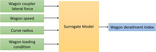
The proposed augmented digital twin for railway systems (ADTR) is shown in Figure . The train control is performed by an ATO which produces notch and dynamic brake (DB) control commands. Modern ATOs implement driving advisory systems that produce locomotive control commands as a function of the train configuration, track layout, train location and speed, to generate optimal train driving plans that minimise energy usage [Citation10] while ensuring speed board compliance. Hence, ATOs use longitudinal train dynamics simulations (LTS) that must be faster than real-time and consider air brakes and non-linear brake connection models to perform correctly. Additional train operational benefits, for example, minimisation of derailment risk, wear or rolling contact fatigue (RCF), require multibody dynamic models for individual vehicles in a train consist, which are more complex and computationally demanding than LTS. The proposed ADTR uses a surrogate model in lieu of vehicle dynamic simulations to allow real-time derailment risk minimisation. The ADTR includes an instrumented coupler on the locomotive that measures the longitudinal coupler force in real-time. Individual wagon lateral coupler forces can then be estimated with a longitudinal train dynamics model and a lateral force calculation model based on track curvatures and vehicle structures using quasistatic calculations [Citation10]. The lateral force value is fed to a surrogate model to produce a derailment risk estimation which, in turn, is used as an input to the ATO which recalculates the train control commands to reduce the derailment index. The Surrogate Model is accomplished using machine learning models trained with an extensive numerical program of wagon multibody dynamic simulations, previously completed on a high-performance computing cluster (HPC). In this way, the ADTR is not only able to consider train dynamics but also wagon performance in optimising a train trip, by augmenting the results of an on-board sensor into more complex vehicle dynamic behaviour parameters in real-time, with the computing power available on-board the vehicle. In this way, unlike a traditional ATO that only enables energy usage optimisation and speed board compliance, an ADTR can be set to reduce more complex parameters such as the DI, wear or rolling contact fatigue (RCF).
Figure 1. Augmented digital twin for railway systems.
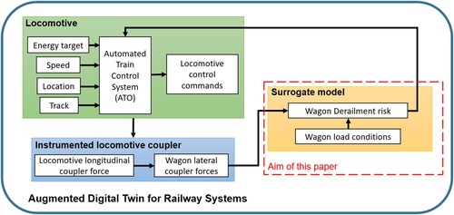
To develop the ADTR, a numerical program comprising a set of 2100 vehicle dynamic simulation was conducted on a HPC. Then, the wagon dynamic behaviour results were postprocessed to obtain a DI for specific operational conditions. This DI dataset is then used to create a surrogate model by training a machine learning regression model. The surrogate model is then implemented in the ATO, using lateral coupler force, train speed, curve radius and wagon loading conditions (wagon centre of gravity position) to predict the instantaneous DI. In this way, the ATO can adjust the locomotive power commands to reduce the tractive effort when a high derailment index is predicted for a wagon. This is especially useful when, because of operational limitations, a loaded train consist includes empty or lightly loaded wagons.
3. Numerical program
The numerical program, comprising the simulation of a typical heavy haul wagon in numerous operating conditions, was implemented in GENSYS multibody dynamic software [Citation15]. The simulated wagon is a 40 t Axle Load (TAL) iron ore wagon. It uses three-piece bogies with Barber type friction wedge suspensions and constant contact side bearings. The bogies use cross-bracing to increase warping stiffness. Detailed parameters used for the wagon modelling are listed in Table .
Table 1. Key parameters of the simulated heavy haul wagon.
Figure shows the three-piece bogie wagon implemented in GENSYS multibody dynamics software. Once the vehicle model was completed, a wagon model acceptance procedure (WMAP) was conducted according to [Citation16]. This acceptance procedure includes model testing scenarios to ensure the wagon model is bug-free, representative of the dynamic behaviour of the wagon in the field and in compliance with Australian dynamic behaviour standards such as [Citation17].
Figure 2. 3D wagon implemented in GENSYS multibody dynamics software. Red lines: wheel-rail contact forces; blue lines: lateral coupler forces.
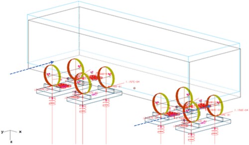
The simulated heavy haul wagon model used ANZR1 and AS60 wheel and rail profiles for all the trips [Citation18,Citation19]. The curved track sections did not consider asymmetric rail profiles. During the simulations, all wheel and rail profiles are assumed to be new profiles, as shown in Figure . The wheel-rail contact model used a geometrical module that allowed up to three contact points at each interface. Contact patch geometries were determined by using Hertz theory for each strip, i.e. a semi-Hertzian model. Normal forces were calculated by using virtual penetrations and a nonlinear spring. The tangential forces, generated when the train applies pneumatic braking on the wagons, were calculated by using the FASTSIM algorithm. The friction conditions were modelled in a similar way as described in [Citation20], using a Hand Operated Tribometer to measure slip-dependent friction characteristics in the field.
Figure 3. New ANZR1 wheel profile and new AS60 rail profile [Citation18,Citation19].
![Figure 3. New ANZR1 wheel profile and new AS60 rail profile [Citation18,Citation19].](/cms/asset/c2ad6f1a-ebff-4f10-9d81-a2d9088df2e5/nvsd_a_2194543_f0003_oc.jpg)
The wagon operating parameters considered in the numerical program are summarised in Table . All the possible combinations of wagon operational parameters result in a numerical program with 2100 simulation cases. Each case was implemented as a sequence of track sections with 100 m of tangent track, 50 m of entry transition, 300 m of circular curve, 50 m of exit transition and 100 m of tangent track. All simulations used typical FRA Class 5 track irregularities [Citation21]. The track used for the simulations was rigid, standard gauge (1435 mm) with a maximum of 40 mm cant and a maximum cant deficiency of 10%. The designed simulation cases put more emphasis on tight curve situations, which is understandable as tighter curves generate larger lateral forces and pose greater challenges for train safety and rail maintenance. The lateral coupler force ranges were determined for each curve radius, and coupler lateral forces will increase from – 100 kN to 100 kN with an increment of 10 kN or 20 kN, i.e. 15 cases. The maximum 100 kN of lateral force is equivalent to 2000 kN longitudinal force with a 0.05 coupler angle (about 3 degrees). The negative or positive symbol for the coupler lateral force represents the force direction, according to the coordinate system presented in Figure . The variations in loading conditions included differences in wagon mass, as well as yaw, pitch, and roll moments of inertia.
Table 2. Wagon simulation operational parameters.
4. Data processing
The derailment index was calculated from the wagon multibody simulation (MBS) results using wheel unloading (WU) and the ratio between the vertical and lateral forces for each wheelset (L/V). WU and the L/V ratio are commonly used derailment indicators for railway vehicles. These two parameters were combined into a derailment index as shown in Figure .
Figure 4. Derailment index (DI) calculation procedure.
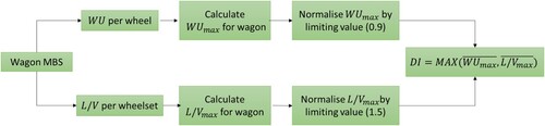
The wagon MBS generates a WU signal per each wheel and an L/V signal per each wheelset for every simulation case along the track section. Then, the maximum wheel unloading and the maximum
ratio (
) are obtained.
and
are normalised according to the Australian Standard AS7509 [Citation17] by factors of 0.9 and 1.5 respectively. Finally, the DI is the higher value of the normalised indicators
and
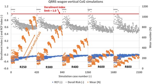
. An automatic data processing algorithm has been developed and implemented on the CQU HPC System [Citation22,Citation23]. This algorithm automatically reads all the files of simulation results and processes per previously discussed steps. Figure shows a summary of the postprocessed numerical program results for the 2100 operational scenarios simulated for the heavy haul wagon. In addition to the DI, results for wear number T-gamma according to [Citation24] and RCF in terms of surface fatigue index based on the shakedown mechanism [Citation25] are also presented. It can be noted that DI values above 1.0 occurred for all curve radii.
Figure 5. Example results for heavy haul wagon vertical CoG simulations.
5. Surrogate model for derailment index prediction
The ADTR to reduce the derailment risk using simulations requires consideration of train and vehicle dynamics. Due to computational limitations, it is not yet viable to perform on-board real-time vehicle multibody simulations to assess the impact of several operational parameter combinations and instantly generate train control commands to ensure a reduced derailment risk. In this case, an ADTR with a surrogate model can be used.
The DI predictor surrogate model is accomplished with machine learning (ML) models trained with the results of numerous vehicle multibody simulations. ML models are a subset of artificial intelligence mathematical tools that can be used to predict the future behaviour of a system based on the previous observations [Citation26]. Linear regression (LR), polynomial regression (PR), decision tree regression (DT) and ensemble forest regression (EF) are four commonly used supervised ML models. For the linear regression model, the derailment index () is the prediction continuous variable, which is calculated with a weighted sum of input features, as shown in Equation 1 [Citation27]:
(1)
(1) where
are the input features, which in this case, correspond to the considered wagon operational parameters: lateral force, speed, curve radius and wagon loading condition.
are the feature coefficients or weights which are learned through previous observations and
is the prediction error. Then, the predicted
is a linear combination of the weighted operational parameters. Furthermore, assuming
to be a nonlinear function of the input features and weights, it is possible to perform a polynomial regression approach. If
is dependent on two features, for example, the basic linear regression case is extended by using second-order polynomial features as follows:
(2)
(2) where the features can be transformed as shown in Equation 3:
(3)
(3) Finally, the
can be predicted using Equation 4:
(4)
(4)
Decision tree regression is a learning algorithm that predicts a specific target variable using a set of rules inferred from a training dataset [Citation28]. Figure shows a simple decision tree, with nodes that evaluate the problem features according to a Boolean test . The decision tree regression algorithm reaches a prediction by conducting a series of consecutive tests. Each test is represented by a tree node. When the sequence of tests reaches a leaf, the algorithm generates a prediction [Citation28,Citation29].
Figure 6. Decision tree example. Redrawn from [Citation29].
![Figure 6. Decision tree example. Redrawn from [Citation29].](/cms/asset/8ed74b46-a5f8-4d5e-83fe-027bc478f915/nvsd_a_2194543_f0006_oc.jpg)
Figure shows the proposed surrogate model for the augmented digital twin for railway systems. The surrogate model estimates a DI from the coupler lateral force, vehicle speed, curve radius and vehicle centre of gravity position inputs.
Figure 7. Derailment index surrogate model schematic of inputs and outputs for augmented digital twin.
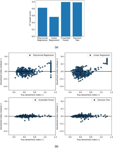
The numerical program results, comprising 2100 simulation cases, were used to train the surrogate model, with 80% of the simulation results used for training and the remainder 20% for testing. The training and testing data subsets were randomly sampled across all the simulation cases, using a predefined random state option to achieve reproducible results for all the ML models, with the train_test_split command from Scikit-Learn [Citation27]. The default parameters of the Scikit-Learn libraries for linear, polynomial, decision tree and ensemble tree regressions were used [Citation27]. Figure a shows the R2 scores for the regression models using the testing dataset. As expected, the non-linearities characterising the dynamic behaviour of railway vehicles cause the linear regression model to have the worst performance, with an R2 score of 0.56, followed by the polynomial regression at 0.82. Decision tree and ensemble forest regression had R2 scores of 0.98 and 0.99 respectively. Figure b shows a residuals plot that allows observing the performance of the regression models across the derailment index spectrum, where the Derailment index residual = 0 line represents a zero-error prediction. The Polynomial Regression (PR) and Linear Regression (LR) models considerably overestimated the derailment index for true derailment index values over 0.8. On the other hand, for true derailment index values below 0.8, LR and PR models produced mixed results, overestimating and underestimating the derailment index. Ensemble Forest (EF) and Decision Tree (DT) models produced consistent derailment risk predictions with EF presenting the lowest residuals results.
Figure 8. Surrogate models DI prediction results using testing dataset. a) R2 testing scores of models; b) DI prediction residual.
6. Case study
A longitudinal train simulation of a heavy haul train was used as a case study for the ADTR. The train was an iron ore head–tail with 2 locomotives, with 32.50 t-axle-load (TAL) + 140 wagons (40 TAL) + 1 locomotive (32.50 TAL). The simulation was conducted using the Centre for Railway Engineering (CRE) longitudinal train simulator (CRELTS) [Citation30]. The case study track curvature and elevation are presented in Figure . The resistance force and gradient force model can be expressed [Citation10,Citation2]:
(5)
(5) where
is the mass of the vehicle in tonnes;
is the axle load of the vehicle in tonnes;
is the vehicle speed in km/h;
is the track curve radius in m;
is the track gradient; and
is the sum of all forces . In the square bracket, the first part in the round bracket indicates rolling resistance; the second part indicates curving resistance; and the third part indicates the gradient force. The train driving controls for the whole trip simulation were generated by using a virtual driver [Citation31]. Locomotive traction and dynamic braking forces were mainly modelled by using the look-up table method. The simulated locomotive traction and dynamic braking power commands (notch) characteristics across the vehicle speed spectrum are shown in Figure .
Figure 9. ADTR case study heavy haul track section.
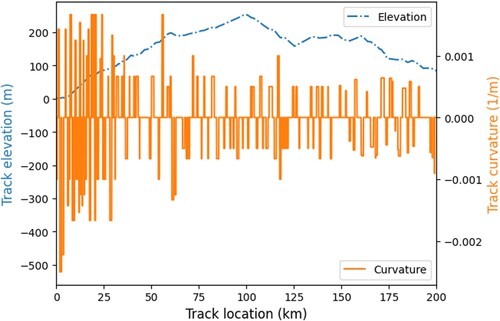
Figure 10. Heavy haul locomotive power command notches characteristics: a) traction; b) dynamic braking.
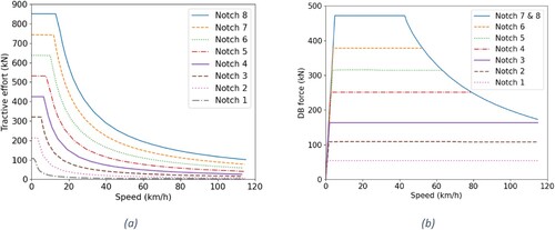
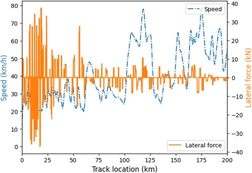
Figure presents the train speed and coupler lateral force for the first wagon after the two leading locomotives, which is expected to have the highest lateral force components. During the simulations, the draft gear force model was expressed as:
(6)
(6) where
is the draft gear force;
is the spring force;
is the friction wedge angle;
is the coefficient of friction; ‘
‘ is set as ‘
‘ for the loading process (wedges are being pushed into the housing) whilst set as ‘
‘ for the unloading process (wedges are moving out of the housing). Having determined the draft gear force, coupler angles can be determined as:
(7)
(7) where
is the coupler angle, rad;
is the coupler pin spacing, m;
is the curve radius, m;
is the bogie spacing, m; and
is the coupler length, m. Having determined coupler angles, coupler lateral forces are simply the product of coupler angles and the coupler forces determined from LTD simulations.
Figure 11. Heavy haul train longitudinal simulation results.
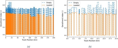
The surrogate model was used to predict the DI for empty and fully loaded conditions, with speed, lateral force from the longitudinal train simulation and track information, as a case study to exemplify the augmented digital twin. Figure shows the DI results for the whole 200 km trip and a zoom-in to the first 20 km. The surrogate model used the EF machine learning approach, as it had the best results with the dataset used for training and testing the model. Two loading conditions variations for loaded and empty wagon were used to test the surrogate model. It can be observed that the surrogate model produced reasonable results, in terms of higher DI for empty wagons and lower DI for loaded wagons, with DI values varying according to different lateral force, vehicle speed and curve radius values.
Figure 12. Surrogate model DI prediction; a) full trip; b) first 20 km.
6. Discussion
This paper developed an ADTR methodology for the prediction of the derailment index in train operations. The ADTR uses multibody simulations and ML to estimate the derailment index in real-time, allowing the ATO to have the information to adjust the train control commands accordingly.
The surrogate model developed for this paper predicted derailment index only, but further implementations of the ADTR may use the same surrogate model approach to generate information regarding other vehicle dynamic behaviour parameters obtainable from MBS. Furthermore, the presented surrogate model used relatively simple ML models, with no optimisations or cross-validation analysis. Nevertheless, the ensemble forest ML model used for the study presented good results for the present case study.
In an eventual ADTR implementation, the scope of the numerical program to develop the surrogate model must be carefully designed. Each type of wagon has a particular dynamic behaviour governed by the primary and secondary suspension characteristics. Thus, a numerical program is required per each type of wagon. Furthermore, for ADTRs that aim at minimising wear and RCF, it is important to consider varying friction and environmental conditions that may affect the creep forces and the wheel-rail material behaviour along the track [Citation32,Citation33]. As digital twin performance depends on the quality and frequency of the feedback from its physical twin, the numerical program to develop the surrogate model must be frequently re-run to ensure the ADTR produces good derailment index predictions. Furthermore, the 2100 simulation cases completed for the ADTR are not enough to consider all the possible operational parameter combinations that occur in railway systems. Key vehicle and infrastructure aspects such as worn wheel-rail profiles, and friction conditions that vary along the track and on the same track location depending on the weather or friction modifiers regime [Citation34], influence the vehicle-track dynamics and the vehicle derailment index. Hence, an ADTR deployment should consider the inputs of track recording vehicles, wayside and other on-board condition monitoring systems to frequently re-train the surrogate model, as the accurate working spectrum of the surrogate model depends directly on the dataset that was used for training the ML model. If the surrogate model is presented with a combination of operational conditions that were not simulated in the numerical program it may produce a misleading prediction.
7. Conclusions
Real-time estimation of derailment index for standard railway revenue vehicles is not currently developed, as wheel-rail contact forces are only measurable with specialised equipment such as instrumented wheelsets which are expensive and impractical for fleet-wide deployments. With industry driven efforts for increasing axle loads and vehicle speeds, specially in heavy haul railway operations, on-board real-time estimation of derailment risk becomes more relevant. This paper developed an augmented digital twin for railway applications (ADTR), envisaged to work with an ATO, enabling the consideration of targeting additional operational benefits such as minimising derailment index, wear or RCF in train operations. The ADTR is based on a surrogate model which, using the results of a massive multibody dynamic simulation program and ML techniques, predicts the derailment index according to the inputs of train consist, vehicle speed, curve radius and lateral coupler forces in real-time. A case study for an iron ore heavy haul train of wagons with three-piece bogies was conducted to demonstrate the ADTR surrogate model. A numerical program consisting of 2100 simulation cases for several combinations of operational parameters was conducted. ML models including linear, polynomial, decision tree and ensemble tree regressions were tested to develop a surrogate model. The ensemble forest regression model performed better than the other models with an R2 score of 0.99 with the numerical program dataset. A longitudinal train dynamics simulation was used to test the developed surrogate model, which was able to produce consistent derailment index estimations according to the wagon load condition. Furthermore, the proposed ADTR method can be used for optimising additional operational benefits that reduce, for example, wheel and rail damage.
Acknowledgements
Dr Qing Wu is the recipient of an Australian Research Council Discovery Early Career Award (project number DE210100273) funded by the Australian Government. The editing contribution of Mr. Tim McSweeney (Adjunct Research Fellow, Centre for Railway Engineering) is gratefully acknowledged.
Disclosure statement
No potential conflict of interest was reported by the author(s).
Additional information
Funding
References
- Wu Q, Spiryagin M, Sun Y, et al. Parallel co-simulation of locomotive wheel wear and rolling contact fatigue in a heavy haul train operational environment. Proc Inst Mech Eng Part F J Rail Rapid Transit. 2021;235:166–178. doi:10.1177/0954409720908497.
- Iwnicki S, Spiryagin M, Cole C, et al. Handbook of railway vehicle dynamics. 2nd ed. Boca Raton: CRC Press; 2019. doi:10.1201/9781420004892.
- Bernal E, Spiryagin M, Cole C. Onboard condition monitoring sensors, systems and techniques for freight railway vehicles: A review. IEEE Sens J. 2019;19:4–24. doi:10.1109/JSEN.2018.2875160.
- Xia F, Cole C, Wolfs P. An inverse railway wagon model and its applications. User Model User-Adapt Interact. 2007;45:583–605. doi:10.1080/00423110601079151.
- Pool A. Digital Twins in Rail Freight-The foundations of a future innovation, (2021) 1–137. http://essay.utwente.nl/88902/.
- Wang Y, Nadarajah N, Oldknow K, et al. Estimating derailment risk using parametric wheel-rail profile characterisation, in: 12th Int. Conf. Contact Mech. Wear Rail/Wheel Syst. (CM2022), Melbourne, Aust., 2022: pp. 4–7.
- Pires AC, Mendes GR, Santos GFM, et al. Indirect identification of wheel rail contact forces of an instrumented heavy haul railway vehicle using machine learning. Mech: Syst Signal Process. 2021;160:107806. doi:10.1016/j.ymssp.2021.107806.
- Guo L, Wang K. Analysis of coupler jackknifing and its effect on locomotives on a tangent track. Proc Inst Mech Eng Part F J Rail Rapid Transit. 2018;232:1559–1573. doi:10.1177/0954409717738429.
- Wu Q, Cole C, Spiryagin M. Characterising stochastic friction in railway draft gear. Veh Syst Dyn. 2022;60:1959–1971. doi:10.1080/00423114.2021.1889003.
- Wu Q, Spiryagin M, Cole C. Longitudinal train dynamics: an overview. Veh Syst Dyn. 2016;54:1688–1714. doi:10.1080/00423114.2016.1228988.
- Wu Q, Cole C, Spiryagin M. Coupler force and fatigue assessments with stochasticdraft gear frictions. J Traffic Transp Eng (English Ed). 2023. doi:10.1016/j.jtte.2021.05.006.
- P. Raj, C. Surianarayanan, Digital twin: the industry use cases. In: Raj P, Evangeline P, editors. Adv comput Vol. 117. [e-book]: Elsevier, 2020: pp. 285–320.
- Glaessgen EH, Stargel DS. The digital twin paradigm for future NASA and U.S. Air force vehicles, Collect. Tech. Pap. - AIAA/ASME/ASCE/AHS/ASC Struct. Struct. Dyn. Mater. Conf. (2012). doi:10.2514/6.2012-1818.
- Xia F, Cole C, Wolfs P. A method for setting wagon speed restrictions based on wagon responses. Veh Syst Dyn. 2006;44:424–432. doi:10.1080/00423110600872465.
- The CALC Func manual. (n.d.). Accessed June 13, 2022. http://www.gensys.se/doc_html/calc_func.html#jwr_coupl_pe3.
- Spiryagin M, George A, Ahmad SSN, et al. Wagon model acceptance procedure using Australian standards, in: Proc. Conf. Railw. Eng., 2012: pp. 343–350.
- RISSB. AS 7509.2:2009 - Railway Rolling Stock - Dynamic Behaviour - Part 2: Freight Rolling Stock, 2009.
- RISSB. AS 7517:2014 - Rolling Stock Standard - Wheelsets, 2014.
- RISSB. Australian Standard - AS 1085.1 - Railway track materials Part 1: Steel rails, 2019.
- Persson I, Spiryagin M, Casanueva C. Influence of non-dry condition creep curves in switch negotiation. Veh Syst Dyn. 2023;61:892–904.
- Federal Railroad Administration. (2014). Track safety standards–Classes 1 through 5, Chapter 1 in: Track and rail and infrastructure integrity compliance manual.
- Central Queensland University. The History of CQU’s HPC facilities, 4 (2023). https://www.cqu.edu.au/eresearch/high-performance-computing/hpc-systems.
- Wu Q, Cole C, Spiryagin M. Parallel computing enables whole-trip train dynamics optimizations. J: Comput Nonlinear Dyn. 2016;11:1–4. doi:10.1115/1.4032075.
- Pearce TG, Sherratt ND. Prediction of wheel profile wear. Wear. 1991;144:343351.
- Johnson KL. A graphical approach to shakedown in rolling contact. In: Hyde T.H., Ollerton E, editors. Appl. stress anal.. Dordrecht: Springer; 1990. pp. 263–274. doi:10.1007/978-94-009-0779-9_26.
- Chenariyan Nakhaee M, Hiemstra D, Stoelinga M, et al. The Recent Applications of Machine Learning in Rail Track Maintenance: A Survey, in: Lect. Notes Comput. Sci. (Including Subser. Lect. Notes Artif. Intell. Lect. Notes Bioinformatics), 2019: pp. 91–105. doi:10.1007/978-3-030-18744-6_6.
- User guide: contents — scikit-learn 1.1.2 documentation, (n.d.). Accessed September 29, 2022. https://scikit-learn.org/stable/user_guide.html.
- Russell SJ. Artificial intelligence a modern approach. Upper Saddle River, New Jersey: Pearson Education, Inc; 2010.
- Gordon AD, Breiman L, Friedman JH, et al. Classification and regression trees. Biometrics. 1984;40:874, doi:10.2307/2530946.
- Cole C, Spiryagin M, Wu Q, et al. Modelling, simulation and applications of longitudinal train dynamics. Veh Syst Dyn. 2017;55:1498–1571.
- Cole C, Mcclanachan M, Simson S, et al. Train Cruise Control. in Proceedings of the 9th International Heavy Haul Conference. 2009;638–645.
- Bernal E, Spiryagin M, Vollebregt E, et al. Prediction of rail surface damage in locomotive traction operations using laboratory-field measured and calibrated data. Eng Fail Anal. 2022;135:106165.
- Bernal E, Spiryagin M, Wu Q, et al. iNEW method for experimental-numerical locomotive studies focused on rail wear prediction. Mech Syst Signal Process. 2022;186:109898. doi:10.1016/j.ymssp.2022.109898.
- Stock R, Eadie DT, Elvidge D, et al. Influencing rolling contact fatigue through top of rail friction modifier application - A full scale wheel-rail test rig study. Wear. 2011;271:134–142. doi:10.1016/j.wear.2010.10.006.