
 ?Mathematical formulae have been encoded as MathML and are displayed in this HTML version using MathJax in order to improve their display. Uncheck the box to turn MathJax off. This feature requires Javascript. Click on a formula to zoom.
Abstract
Out-of-roundness in railway wheels, in particular polygonal wear resulting in regular, multi-lobed, out-of-round wheels, has become a significant problem in recent years. It is of concern to railway operators due to the increased noise and vibration it can cause. This polygonisation is caused by cyclic wear but the exact mechanism leading to this type of wear is not fully understood. It appears to be the result of dynamic linking between a resonance or other periodic excitation in the coupled vehicle–track system and the existing wear at the wheel. This paper reviews the developing body of research being carried out in many countries by research groups, manufacturers and operators. Some examples of polygonisation on different types of railway vehicles are reported including feight trains, urban transit trains and high-speed trains. The main theories for the formation mechanisms are presented and the current measurement methods, computer simulation techniques and the effects and potential mitigation methods are reviewed. In parallel, the mechanisms and consequences of discrete wheel tread irregularities, such as wheel flats and material fall-out due to rolling contact fatigue cracking, are addressed.
1. Introduction
Wheel out-of-roundness including polygonal out-of-roundness caused by polygonisation (or polygonalisation) is one of the most common defects on the wheel tread in railway vehicles and can cause high levels of vibration and noise which can be a significant problem for railway operators. Discrete wheel tread irregularities, being another form of out-of-roundness, may lead to momentary loss of wheel–rail contact and severe impact loading. This could lead to rail breaks and sleeper cracking, high-cycle fatigue of wheels and other vehicle components. Other effects include the generation of impact noise and ground-borne vibration.
This paper reviews the main research activity in this area in recent years. After summarising the theories relating to wheel polygonisation on different types of rolling stock, the paper goes on to review the development of simulation methods for predicting polygonisation, its causes and its measurement and the techniques that some railway systems are developing to control polygonisation and to limit its effects. Further, models for simulation of high-frequency wheel–rail impact are addressed and compared with field measurements. Based on measurement of impact loads in wayside detectors, international alarm limits prescribing removal of out-of-round (OOR) wheels are surveyed.
Since 1993 there have been many research projects in Europe dealing with wheel polygonisation and OOR wheels, mainly concerning low-order polygonisation. Wheel machining, lower bending and torsional modes of wheelsets and the P2 resonance were considered to be the main causes of low-order wheel polygonisation. More recently wheel polygonisation has become a hot research topic in China with more than 30 listed international journal and conference papers dealing with the mechanism of polygonisation of locomotive, metro and high-speed wheels by Chinese researchers since 2010. Studies in other countries include work by Transnet Freight Rail in South Africa, where locomotives have suffered from wheel polygonisation since 2015 and significant efforts have been made to deal with this problem. The authors acknowledge previous reviews on this and related topics including those by Nielsen et al. [Citation1–3], by Barke et al. [Citation4] and by Tao et al. [Citation5].
This paper starts by defining some key terms. It then describes the main mechanisms of polygonisation for different types of railway vehicles including for locomotives, for urban rail transit trains and high-speed trains and considering the influence of drives and traction control systems. Discrete types of out-of-roundness (such as wheel flats) are specifically discussed in Section 4, while the state-of-the-art in measurement both from vehicle and from the trackside is covered in Section 5. Simulation of wheel out-of-roundness is reviewed in Section 6, and in Section 7 the effects of out-of-roundness on different elements of the railway system are discussed. Operational aspects are covered in Section 8 and some mitigation methods are described in Section 9 before overall conclusions are drawn.
2. Definitions
Some of the terms related to out-of-round wheels are used in slightly different ways by different groups so the authors of this paper felt it would be useful to define the meanings of the fundamental terms as they are used in this paper:
Wheel out-of-roundness – any deviation from a perfectly round wheel (which could be discrete or periodic or random).
Polygonal wheel – a wheel with a regular (periodic) variation in radius. The order of the polygonal irregularity is the number of lobes or positive deviations from the average radius seen in one complete revolution of the wheel. The wavelength of the out-of-roundness commonly observed varies from one wheel circumference (1st order or an eccentric wheel) down to around 10 cm (28th order).
Polygonisation – the process which results in polygonal wheels.
Wheel flat – a discrete defect (flat point) on the wheel surface often caused by wear during sliding of a locked wheel. There may be multiple wheel flats on a wheel but they are not usually regularly spaced around the wheel.
Wheel roughness – a random, surface irregularity on the wheel tread with relatively small amplitude and short wavelength.
P1 resonance – a resonance where the vehicle unsprung mass and the track mass are vibrating in antiphase across the wheel–rail contact stiffness
P2 resonance – a resonance where the unsprung mass of the vehicle and the equivalent track mass are vibrating in phase on the equivalent stiffness of the track
3. Mechanisms of wheel polygonisation
There are different theories on the formation of polygonal wheels and there seem to be a number of different mechanisms operating even for the same type of rolling stock. In this review article, the focus includes the formation of polygonal locomotive, urban rail transit and high-speed wheels. In this section, key observations of wheel polygonisation are summarised followed by a discussion on possible formation mechanisms.
3.1. Polygonisation of locomotive wheels
There are many observations of polygonisation in locomotive wheels. In the European project RIVAS (Railway Induced Vibration Abatement Solutions), it was reported that some wheels of the TRAXX locomotives in Switzerland exhibited wheel polygonal wear with orders 14 and 28, and dominating wavelengths of 315 and 160 mm in 1/3 octave bands. There were few detailed measurements, and it was uncertain whether wheel polygonisation was a common problem or not for this type of locomotive. Because the project focused on train induced ground vibration, the formation of wheel polygonisation was not a major concern although it was pointed out that the periodic wear on the TRAXX locomotives may be influenced by the locomotive design [Citation6].
Several types of high-power alternating current (AC) drive electric locomotives in China have suffered from wheel polygonisation. With funding from the China Railway Rolling Stock Corporation (CRRC) and the National Natural Science Foundation of China (NSFC), several projects have been conducted since 2013 to investigate the features, formation, influence factors and countermeasures of polygonisation of locomotive wheels and some important results are summarised in Figure . The extensive measurements indicated that three types of locomotive exhibit polygonal wheel wear with orders 17–19 and 24 [Citation7,Citation8].
Figure 1. Summary of some important results on locomotive wheel polygonisation research in China. Figure based on assembly of figures from [Citation7–14].
![Figure 1. Summary of some important results on locomotive wheel polygonisation research in China. Figure based on assembly of figures from [Citation7–14].](/cms/asset/70af6aa3-ebe9-4c97-9f59-21920986c8fa/nvsd_a_2194544_f0001_oc.jpg)
Some experiments, including wheelset modal tests, frequency response tests of the track system and locomotive vibration on-track test, were carried out to investigate wheel polygonisation on locomotives. Simulations of wheel wear evolution were also performed. The research results indicated that the bending modes of the wheelset were responsible for wheel polygonisation [Citation9–11]. Although the design of the wheelsets had some differences, the natural frequencies related to wheel polygonisation were found to be similar. The natural vibration of the wheelsets can be easily excited by discrete wheel tread irregularities [Citation12], residual wheel polygonisation after re-profiling [Citation7,Citation8], and rail weld irregularities [Citation11]. In addition, the running speed profile of the locomotive is basically the same when it runs on the same route. Therefore, polygonal wheels with a fixed wavelength can be easily formed under the excitation of a fixed frequency mechanism. Further research showed that qualities of wheel re-profiling [Citation7,Citation10,Citation11], route gradient [Citation11,Citation13], the threshold of the anti-slip controller [Citation14], and fixed operation mode [Citation11] play key roles in the formation of polygonal wheels.
One type of AC locomotive in South Africa has suffered from serious wheel polygonisation since 2015. The locomotive has a Bo-Bo bogie configuration and has a maximum running speed of 120 km/h, however, it often operates at below 80 km/h. The dominating harmonic order of wheel polygonisation is 20, and the cumulative OOR distribution on the non-gear and gear sides has a significant difference. That is to say, wheel polygonisation on the same wheelset presents an asymmetric feature.
Based on the features of wheel polygonisation for this locomotive type, the researchers considered that the first-order axle torsional mode plays a key role in the formation of polygonal wheels as the nodal point of this mode is not at the centre of the axle, which can cause an asymmetrical torsional response. A simplified mass-spring-damper model of the bogie and extensive field experiments concerning wheel–rail dynamic response, motor power, and vibration were carried out to investigate the formation of polygonal wheels. Some interesting results were obtained and indicated that the coupled mode of traction motor pitching and wheelset torsion at approximately 56 Hz is the root cause of the asymmetrical wheel polygonisation [Citation15]. Self-excited stick slip vibration under saturated adhesion, especially on curved tracks, and forced excitation by the harmonics and inter-harmonics from a variable frequency drive (VFD) for the AC traction motor are two potential excitation sources of the torsional vibration, see Figure . The second excitation mechanism was considered to be the main reason for the polygonisation [Citation16,Citation17]. Further investigations indicated that the coupled vibration of traction motor pitching and wheelset torsion can be excited by the 5fg–7fm inter-harmonic when the locomotive is running at a speed of approximately 40 km/h [Citation16], where fm and fg are the fundamental frequency of the VFD and the input AC frequency supplied to the VFD, respectively.
Figure 2. Main causes of locomotive wheel polygonisation in South Africa [Citation15,Citation16]. (a) Self-excited stick–slip vibration on the curve and (b) the excited torsional vibration by inter-harmonics measured at the motor nose link.
![Figure 2. Main causes of locomotive wheel polygonisation in South Africa [Citation15,Citation16]. (a) Self-excited stick–slip vibration on the curve and (b) the excited torsional vibration by inter-harmonics measured at the motor nose link.](/cms/asset/0a00dfeb-6e9f-43d7-a0c5-57c6d15b0f8c/nvsd_a_2194544_f0002_oc.jpg)
Two countermeasures were proposed to suppress the formation or development of polygonal wheels on the South African locomotives [Citation15,Citation17]. The first solution was to use a control system to detect and arrest the torsional vibration, which does not require any hardware upgrades and works as a mitigation measure whether the vibration originates from self-excited stick–slip or VFD of the AC traction motor. This approach not only reduces the amplitude of the 5fg – 7fm inter-harmonic, but also increases the damping from the wheel–rail contact. The shortcomings of this solution are that it cannot completely eliminate the coupled resonance mode, and the traction effort of the locomotive is reduced significantly when the torsional vibration detected by the controller exceeds a defined threshold. The second solution is to eliminate the 5fg – 7fm inter-harmonic oscillation at specific speeds, which can be implemented through changing the predetermined speeds where the pulse mode is changed, installing an output harmonic filter and increasing the pulse rate of the inverter. The control software was updated to change the pulse mode from 41.5 km/h to 45 km/h. The resonance of the coupled mode is greatly eliminated by the new control software.
3.2. Polygonisation of urban rail transit wheels
Urban rail transit trains usually run on limited routes, and the operation mode is relatively consistent, especially for systems with automatic train operation. The problem of wheel wear, especially polygonal wheel wear, has been a significant issue for many urban rail transit operators.
Nielsen et al. reported a case of wheel polygonisation on one of the metro lines in Stockholm [Citation2]. Approximately 60% of all wheels had a dominating harmonic order of 3, corresponding to a wavelength of 0.8 m. The researchers postulated that an initial OOR with three harmonics was caused by wheel machining with a three-jaw chuck. Johansson and Andersson [Citation18] investigated the evolution of wheel polygonisation on the Stockholm metro through a simulation of three-dimensional dynamic wheel–rail interaction and wear. They found that the development of polygonal wheel orders 14–20 were caused by the vertical track anti-resonance at 165 Hz, while the increase of the orders 5–7 were due to the P2 resonance (at 40 Hz) and the sleeper passing excitation (at 34.7 Hz) at a speed of 50 km/h. However, the continued growth of the third-order wheel polygon was not reproduced by the simulations. Through a private communication with the train manufacturer, one hypothesis is that the growth of the third-order wheel OOR may be caused by the braking or traction system [Citation18].
In addition to the case reported by Nielsen et al., many other cases of metro wheel polygonisation have been reported. Jin et al. made a detailed summary of the problem of metro wheel polygonisation in China [Citation19]. This issue is very complicated and highly dependent on the type of metro trains and operation. For example, metro trains running on several lines in China suffer from severe wheel polygonisation. However, in some cases, the same type of metro train runs on other lines without the same problem occurring. This phenomenon may be related to track form and/or the distribution of curve radius. It has been reported that trains on lines with a larger proportion of small radius curves exhibit more wheels with polygonal out-of-roundness than trains running on lines with fewer tight curves [Citation6]. Different theories that have been proposed to explain the formation of polygonal wheels of metro trains will be discussed below.
The first reported case of wheel polygonisation on metro trains in China was found on one of the metro lines in Guangzhou in 2008, where metro trains use linear induction motors (LIM train). The dominating harmonic order is 9. After conducting extensive experiments on field sites, Jin et al. [Citation20] found that the first bending resonance of the wheelset is easily excited during running. Therefore, it was concluded that the first bending resonance of the wheelset is the root cause of the ninth-order wheel polygon.
Chen et al. [Citation21] also investigated this problem based on the theory of frictional self-excited vibration of the wheelset–track system. They found that the frequencies of several unstable stick–slip modes under saturated adhesion are consistent with the passing frequency of the polygonal wheel and pointed out that frictional self-excited vibration is one of the causes of wheel polygonisation of the LIM train.
Generally, the passing frequency of a fixed-wavelength polygonal wheel or rail corrugation can be determined by the formula of f = v/λ, where v is speed and λ is wavelength of the wheel polygon or rail corrugation. Ma et al. [Citation22] proposed that if the relation of mf = v/λ is met, where m is an integer, the wheel polygon can be formed. Based on this idea, they believed that the 9th order wheel polygon of the LIM train is caused by the vertical vibration of the linear induction motor with a frequency of about 43.5 Hz when the train runs with speed between 72 and 80 km/h. Fu et al. [Citation23] studied this problem through simulation of polygonal wear evolution. They suggested that the polygonisation occurred in two stages. First, the residual polygonal wear with four harmonics after wheel re-profiling can excite the vertical vibration of the LIM train, which led to the evolution of the 4th order polygon into that of 8th to 9th order. Then, polygonal wheel wear with 8th to 9th harmonics excited the first bending resonance of the wheelset, which accelerates the wheel wear with 8th to 9th harmonics. It is worth noting that the metro operator conducted an experiment, in which the linear induction motor of one bogie was removed. However, the 9th order wheel polygon was still formed and extended, thus indicating that the ninth-order wheel polygon is independent of the LIM.
In addition to the LIM train, wheel polygonisation also occurs on other metro trains. Tao et al. [Citation24], Cai et al. [Citation25], and Mu et al. [Citation26] found that the P2 resonance is the main reason of a wheel polygon with 5–8 harmonics for the metro train with a maximum running speed of 80 km/h. Yang et al. [Citation27] showed that the combination of the P2 resonance with the first order bending resonance of the wheelset is the root cause of a wheel polygon with 13th to 16th harmonics (wavelengths of 160 to 200 mm) for the train running on one of the metro lines in Beijing.
Tao et al. [Citation28] studied a case of asymmetric polygonal wear on metro train wheels. This was found to be different from the asymmetric polygonal wear of locomotive wheels reported by Transnet Freight Rail in South Africa [Citation15]. Both the trailing and motored wheelsets showed polygonisation with orders 12–14, and the polygonisation of the right wheels was more serious than that of the left wheels on all trains studied. It was concluded that the first bending resonance of the wheelset excited on sharply curved tracks was the root cause of the wheel polygonisation. It should be noted that the running direction of the train cannot be reversed in this line, and the total length of right-hand curves is much longer than the left-hand curves, which plays a vital role in the formation of asymmetric polygonal wear. A further study was conducted by Yang et al. [Citation29]. They pointed out that the first bending mode of the wheelset presents an obvious feature of asymmetry as constrained by the rails on sharp curves. The dynamic wheel–rail interaction on the low rail side in curves is more distinct than that on the high rail side, which further promotes the development of asymmetric polygonal wear. Based on the theory of frictional self-excited vibration, Kang et al. [Citation30] also studied the asymmetric polygonal wear problem of metro train wheels. They found that the unstable vibration intensity of the wheel–rail system on the low rail side is much stronger than that of the high rail side under saturated adhesion conditions, which plays an important role in the formation of asymmetric polygonal wear.
In addition to metro trains, some trams and light rail vehicles also suffer from wheel polygonal wear [Citation31–35]. Lulu et al. [Citation31] found that the wheels of one type tram with 70% low-floor technology showed polygonal wear with order 10. Staśkiewicz et al. [Citation33] reported that two types of tram (high-floor and low-floor) clearly exhibited ‘triangle’ polygonisation for both new and worn wheels. However, there are relatively few studies on the mechanism of wheel polygonisation of trams or light rail vehicles. Zehetbauer et al. [Citation34,Citation35] studied the formation mechanism of order 17–20 polygonal wear of tram wheels through numerical simulation, and they pointed out that the self-excited vibrations when the tram passing through small radius curves may be a cause, but it needs future research. The study by Kurzeck and Hecht [Citation36] showed that self-excited oscillation of the wheelset or the bogie could occur for curve negotiation, which can result in squealing, wheel polygonisation or rail corrugation.
3.3. Polygonisation of high-speed train wheels
Polygonisation of high-speed train wheels was first reported on ICE trains in Germany. The third- and second-order OOR defects were dominant on standard solid steel wheels and rubber-sprung wheels, respectively. Rode et al. [Citation37] investigated the cause of an initial polygon with three harmonics. They found that this was formed from the fixation procedure during wheel machining, where the wheelsets are fixed with a three-jaw chuck at three equidistant positions. Elastic deformation occurs on the wheel rim at the fixed positions. After wheel machining the wheel rim returns to its undeformed shape which causes an initial third-order polygon. Simulations performed by Morys [Citation38] indicated that the first-order bending oscillation of the wheelset and the P2 resonance can be excited by an initial third-order polygon, which promotes the enlargement of wheel out-of-roundness, see Figure .
Figure 3. Long-term wheel OOR evolution presented by (a) the wheel shape changes and (b) the radius reduction [Citation38].
![Figure 3. Long-term wheel OOR evolution presented by (a) the wheel shape changes and (b) the radius reduction [Citation38].](/cms/asset/9e1c052c-0183-4678-809e-db73e5a3d96b/nvsd_a_2194544_f0003_ob.jpg)
Since 2014, polygonisation of high-speed train wheels in China has become a serious problem and a great deal of effort has been made to study its formation mechanisms. After having reached a sufficient understanding of this problem, polygonisation on high-speed train wheels is gradually being effectively suppressed. In this section, different theories on formation mechanisms are surveyed. However, some practical experience to suppress polygonisation of high-speed wheels in China will be summarised in Section 8. Different from the wheel polygonisation occuring on the ICE high-speed trains, higher periodic orders have been observed on different types of high-speed trains in China. Wang et al. [Citation39] summarised the features of polygonal wear for Chinese high-speed train wheels based on an extensive number of wheels measured on field sites. It was noted that the wavelengths of the wheel polygonisation are in the range of 100 mm to 180 mm, depending on the train type, track type and operating speed. There is no consensus on the formation mechanisms for high-speed wheel polygonal wear in China, but Chinese researchers have recently been investigating three main possible causes: (1) bogie component vibration, (2) rail bending modes constrained by the bogie wheelbase, and (3) frictional self-excited vibration of the wheelset–track system.
3.3.1. Bogie component vibration
Wu et al. [Citation40–42] have been investigating this mechanism recently. Based on a series of field experiments and simulations, they concluded that an excited resonance of the bogie during high-speed train operation is responsible for the polygonal wheel wear, and pointed out that the key frequency related to the formation of polygonal wheel wear is approximately 580 Hz [Citation40]. Then, Wu et al. [Citation41] developed a polygonal wear simulation model to study the key factors of the initiation and development of polygonal wheels. The track dynamics was considered, however, only one mode shape of the wheelset (576 Hz) was considered in the dynamics model. Effects of wheel diameter and running speed on the development of polygonal wheel wear were investigated. They found that the ‘Integral Multiple Condition’ (see Section 8.1) is an important factor for the formation and development of the wheel polygon.
Recently, Wu et al. [Citation42] carried out fundamental experimental research on a full-size wheel–rail roller test rig in the High-speed Wheel–rail Relationship Laboratory in the China Academy of Railway Sciences to further verify their theories, see Figure . This was the first time that polygonal wheel wear had been reproduced on a full-size test rig under laboratory conditions. There was no traction or external excitation applied to the test wheelset, and the main excitation source was only the initial random irregularities on the wheel–rail contact surfaces. Experimental modal analysis determined that the damping ratio of the second-order bending mode of the wheelset (149 Hz) is minimal. A test was performed, in which the speed was set to 306 km/h and it was found that the ‘Integral Multiple Condition’ could be satisfied in that condition if the second-order bending vibration of the wheelset was excited. As they expected, the 5th order polygonal wear was gradually formed during the test, which indicated that the bending resonance of the wheelset is an important factor for wheel polygonisation. However, the reproduced polygonal wear was of a lower order to that found on the high-speed train in China. Therefore, how to reproduce the higher-order harmonics under laboratory conditions with a full-size test rig is still an open question.
Figure 4. Reproduction of wheel polygonal wear on a full-size wheel–rail roller test rig [Citation42]. (a) Photograph of the full-size wheel–rail roller test rig, (b) time-frequency spectra of the vertical acceleration of the axle box, where the second-order bending vibration of the wheelset (149 Hz) can be excited during the test, (c) the reproduced polygonal wheel wear for a constant speed. The wheel diameter is approximately 908 mm. If the second bending vibration of the wheelset is excited during the test, polygonal wheel wear with five harmonics could be formed under a running speed of 306 km/h, and (d) Evolution of the vertical axle box acceleration during the test.
![Figure 4. Reproduction of wheel polygonal wear on a full-size wheel–rail roller test rig [Citation42]. (a) Photograph of the full-size wheel–rail roller test rig, (b) time-frequency spectra of the vertical acceleration of the axle box, where the second-order bending vibration of the wheelset (149 Hz) can be excited during the test, (c) the reproduced polygonal wheel wear for a constant speed. The wheel diameter is approximately 908 mm. If the second bending vibration of the wheelset is excited during the test, polygonal wheel wear with five harmonics could be formed under a running speed of 306 km/h, and (d) Evolution of the vertical axle box acceleration during the test.](/cms/asset/060dbc00-b404-4b96-8308-5f2b3f65354b/nvsd_a_2194544_f0004_oc.jpg)
3.3.2. Rail bending modes constrained by the bogie wheelbase
Dai et al. [Citation43] were the first to use this hypothesis to explain the initiation mechanism of polygonal wear of high-speed EMU wheels in China. Based on the statistical results of features of wheel polygonisation on different types of EMUs, they found that the passing frequencies of the polygonal wheel are related to the sleeper spacing and bogie wheelbase. Furthermore, they pointed out that the frequencies of the third-order bending mode of the rail as constrained by the bogie wheelbase (based on numerical modal analysis of the rail, ranging from 550 to 650 Hz depending on the sleeper spacing, bogie wheelbase and fastener vertical stiffness) are close to the passing frequencies of the wheel polygon. In a follow-up study, Qu et al. [Citation44] detected a similar vibration mode in a lab test. Wu et al. [Citation45] studied the influence of rail bending modes on high-order wheel polygonisation through wheel wear simulation. The frequency of the third bending mode of the rail between the two wheelsets of the same bogie was about 650 Hz, and it was shown that it had a significant influence on the vertical wheel–rail contact force. In a long-term wear simulation, high-order wheel polygonal wear was formed, which was in good agreement with field tests. Thus, it was concluded that this mode is the primary contributor to high-order polygonisation. However, the passing frequency of the simulated polygonal wheel is about 555 Hz, and the reason for the difference between the natural frequency of the third-order local rail bending and the passing frequency of the simulated wheel polygon was not well explained. Nevertheless, Cai et al. [Citation46–48] have made important contributions to support this point of view. In particular, they explained the reason why there is a difference in frequency between the excitation of the local rail bending mode and the response of the formed wheel polygon. The growth ratio of polygonal wear defined by Peng et al. [Citation49] was used,
(1)
(1) where A and B are the initial amplitude of the polygonal wear and the amplitude of the wear fluctuation, respectively, while φ is the phase lag of the instantaneous wear with respect to the initial polygonal amplitude. Thus, the polygonal wear growth rate is determined by both the amplitude of the wear response (B/A) and the phase lag (φ). If the phase lag φ is in the range of 90° to 270°, the out-of-roundness tends to increase continuously and will have the highest growth rate when the phase lag is close to 180°. Although there is a peak value at about 650 Hz for the wheel–rail contact force induced by the third-order rail bending resonance between the two wheelsets of the same bogie (see the upper figure of Figure ), the phase lag at this frequency is larger than 270° (see the middle figure of Figure ). The phase lag at approximately 330 and 565 Hz is in the range of 90° to 270°, therefore, the dynamic responses around these two frequencies play a vital role for the formation of wheel polygonal wear. As a result, the peak values for the polygonal wear growth rate occur at approximately 342 and 570 Hz (see the lower figure of Figure ). Therefore, the formed wheel out-of-roundness is decided by the characteristics of the polygonal wear growth rate [Citation46,Citation47]. Similar conclusions were made by Ma et al. [Citation50].
Figure 5. Frequency response of vertical wheel–rail contact force and growth trend of polygonisation [Citation47]. The frequency response of polygonal wear is similar to that of vertical wheel–rail contact force, see [Citation47]. Dashed line: single wheelset, solid line: multiple wheelsets.
![Figure 5. Frequency response of vertical wheel–rail contact force and growth trend of polygonisation [Citation47]. The frequency response of polygonal wear is similar to that of vertical wheel–rail contact force, see [Citation47]. Dashed line: single wheelset, solid line: multiple wheelsets.](/cms/asset/aab3ccf7-7f92-4f2c-b04f-2a96adde1dd4/nvsd_a_2194544_f0005_oc.jpg)
3.3.3. Frictional self-excited vibration of the wheelset–track system
The theory of frictional self-excited vibration has been used by some researchers to explain the formation of rail corrugation and wheel polygonisation, as well as brake squeal. The eigenvalues of the wheelset–track system in a finite element model can be determined by solving the equation , where x is the node displacement vector and M, C, and K are the mass, damping and stiffness matrices, respectively. If frictional forces between the coupled wheelset and track are considered, solving the eigenvalue problem will lead to complex eigenvalues. If one (or more) of the eigenvalues has a positive real part, the mode at that frequency will lead to unstable vibration, which could cause rail corrugation or a wheel polygon. When using this theory to study the formation of rail corrugation or wheel polygonisation, it is worth noting that the wheel–rail creep force is assumed to be saturated. Kang et al. [Citation51], Wu et al. [Citation52,Citation53], and Zhao et al. [Citation54,Citation55] explained wheel polygonisation on high speed train wheels by employing this theory. They found there are some unstable modes of the wheelset–track system between 500 Hz and 650 Hz, which may cause the high-order harmonics on wheels.
3.4. Discussion on wheel polygonisation on high-speed trains
Why does the wheel form polygonal wear? This is a serious scientific issue that needs to be treated systematically. From the point of view of wear, it is a wavelength-fixing wear mechanism. However, from the point of view of system vibration, it is a frequency-fixing mechanism caused by external excitation or self-excitation vibration. The wavelength of polygonal wear is determined by the speed of the vehicle and the excited frequency (λ = v/f). However, the coupled vehicle–track system is a complex non-linear system, and the number of natural frequencies of the vehicle and track components are abundant. For a given vehicle speed, it seems always possible through experiment or simulation to find a frequency of the coupled vehicle–track system that could explain the wavelength of the formed wheel polygon. It is more important to validate whether the vibration at that frequency can be excited or not during vehicle operation. However, in some articles, the authors only found a frequency related to the wheel polygonisation and believed that it is the root cause of polygon formation, which is a limitation of this approach.
Chinese researchers have developed different theories for the mechanisms of polygonisation on high-speed railway vehicles in China. As surveyed above, there are three main theories although these do not seem to fully explain the mechanism of polygonal wheel wear. According to the first theory, a bogie component vibration is the root cause. However, this cannot explain why there is a difference in wavelength for the same type of high-speed EMUs running on different lines at the same operating speed. For example, for the same type of high-speed EMUs running on the Harbin-Dalian and Wuhan-Guangzhou high-speed railway lines, the averaged wavelengths of the polygon are132mm and 152 mm, corresponding to a passing frequency of 635 and 549 Hz, respectively.
The second theory indicates that a rail bending mode, which mainly depends on rail bending stiffness, sleeper spacing, bogie wheelbase and fastener vertical stiffness, is the root cause. Simulations and field tests show that the frequency of one rail bending mode, which could be related to the polygonal wheel, is approximately 645 Hz [Citation47]. However, the passing frequency of the polygonal wheel is about 572 Hz. Phase lag of the polygonal wear rate was introduced to explain this difference between the excited frequency and the wheel polygon passing frequency. The statistical results presented by Dai et al. [Citation43] revealed that the passing frequencies of the wheel polygon are highly related to the sleeper spacing and bogie wheelbase. Thus, the hypothesis of a rail bending mode combined with the phase lag of the polygonal wear rate seems to explain this phenomenon. However, when the vision is broadened to a wider scope, it can be concluded that Europe and Japan have reported few problems of high-order wheel polygonisation on their high-speed trains. Since rail bending modes also exist in the high-speed railways of Europe and Japan, why does it not cause a wheel polygon? In addition, rail bending vibration also exists in conventional railway and metro lines.
The third theory suggests frictional self-excited vibration of the wheelset–track system to be the root cause. The prerequisite of this theory is a saturated creep force. However, extensive test results indicate that polygonal wear occur on both trailer and motor wheels, and the wavelength of those wheels is the same. Generally, the creep force on trailer wheels rarely reaches saturation. In addition, it is difficult to verify whether the creep force is saturated or not by test.
3.5. Drives and control systems
Modern railway vehicles are fitted with sophisticated traction control and wheel-slide protection systems which interact with the traction and braking systems to ensure efficient traction and braking. There is some recent evidence that these systems can cause or exacerbate wheel out-of-roundness and this has been studied by some researchers.
Spangenberg and Fröhling [Citation17] reviewed component fatigue failures on a freight locomotive caused by polygonal wheels and found that the traction motor drive control system was exciting resonances when coupling with the 20th order polygon of the wheel at specific speeds. The model of mechanical linkages between the motor and the wheelset were validated against results from on-track tests.
Yang et al. [Citation14] investigated the effect of anti-wheel slip controllers on the evolution of polygonal wear on locomotive wheels. A multibody model and wear predictor was used with the flexibility of the wheelset included through modal properties. The threshold of action of the wheel slip controller was investigated and it was found that the level of this threshold had a clear effect on the development of polygonal wheel wear. The authors summarised the initiation mechanisms of polygonal wear for high-speed and metro vehicles, see Table , and recommended using a lower threshold for the anti-slip controller.
Table 1. Classification of initiation mechanisms of wheel polygonal wear for high-speed and metro vehicles. (From Yang et al [Citation14]).
Cai et al. [Citation47] also investigated the coupling between multiple wheelsets on high-speed trains. Models in both time and frequency domains, and a non-linear wear predictor, were used. The results were validated against on-track measurements and a rail bending resonance was found to be a significant wavelength-fixing mechanism.
Chen et al. [Citation56] investigated the effect of the drive and transmission systems on polygonal wear. The model included the traction motor properties and the wheelset flexibility, and a comparison was made between the predictions with and without the drive system model.
4. Discrete wheel tread irregularities
A discrete wheel tread irregularity is a deviation from the nominal wheel radius along a short section of the wheel circumference. It is a local surface damage that for example could be induced by rolling contact fatigue (RCF) or a consequence of the wheel sliding without rolling (wheel flat). In general terms, surface initiated RCF is the result of severe frictional rolling contact leading to progressive plastic deformation (ratchetting) that eventually causes crack initiation if the material strength is exceeded [Citation57,Citation58]. Subsequent crack propagation, aggravated by the presence of fluids trapped inside the cracks, and material fall-out leading to deteriorated contact conditions may cause a cluster of tread defects which with progressive material fall-out eventually may cause the formation of a long tread irregularity.
The reason for the sliding may be that the brakes are frozen or defective, or that the braking force is too high in relation to the available wheel–rail friction. Part of the wheel tread is worn off and locally the wheel temperature is raised significantly due to the dissipated friction energy. When the wheel starts rolling again, this is followed by a rapid cooling that may lead to the formation of martensite and residual stresses [Citation59]. Cracks may initiate and propagate in the brittle material due to the rolling contact loading and the repeated impacts. Due to the tensile residual stresses in the surrounding material, cracks may grow to considerable depths and pieces of the wheel tread may detach aggravating the irregularity.
As indicated by the vertical wheel centre trajectory generated by a discrete wheel tread irregularity [Citation60], the resulting dynamic wheel–rail interaction leads to an abrupt change of vertical momentum, potentially causing a momentary loss of wheel–rail contact followed by an impact on the rail. The loading is a transient event, and with each wheel revolution periodically repeated, exciting vibration in a wide frequency range with most of the energy concentrated below about 1 kHz. The impact loading can damage the rails, in extreme cases even leading to rail breaks [Citation61]. For tread irregularities not leading to momentary loss of wheel–rail contact, the excitation is dominated by lower frequencies that may damage sleepers and ballast. Discrete defects may also cause high-cycle fatigue of wheels and other vehicle components, such as bearing failures. Other consequences include the generation of impact noise and ground-borne vibration [Citation3].
The implementations of improved brake system design and wheel material quality, and wheel slide protection, can mitigate the generation of wheel flats. RCF can be prevented by enhanced vehicle steering and friction management that reduce the tangential loading, and by controlling the wheel/rail profiles [Citation58]. The unsprung mass is the key vehicle-related parameter influencing the magnitude of the impact load. Means for reducing the unsprung mass, including alternative designs for the wheelset and the suspension of the mechanical drive system, are discussed in Refs. [Citation62,Citation63].
5. Measurement of wheel out-of-roundness
Wheel out-of-roundness can cause intense vertical wheel–rail contact forces including impact loads, which have great effects on the service performance of the rolling stock and infrastructure components, as well as on riding comfort, noise and ground-borne vibration. Therefore, it is particularly important to detect and mitigate (by wheel turning) OOR wheels in time if they do not meet the operational requirements. A survey of available approaches to detect wheel defects, including wheel flats, cracks, spalling, shelling, etc. is found in Alemi et al. [Citation64]. In this section, methods used for measurement and detection of wheel out-of-roundness are summarised, including: (1) direct wheel out-of-roundness measurement instruments, (2) wayside detection and (3) onboard detection.
5.1. Direct wheel out-of-roundness measurement instruments
Several measurement instruments are available to measure wheel out-of-roundness and roughness. Not only the radial run-out, but also the irregularity around the wheel circumference can be measured with probes in contact with the wheel tread. The accuracy of these instruments is high, but they are time-consuming and labour-intensive to use. This measurement method plays an important role in the study of wheel OOR features, mechanisms and evolution rules [Citation7,Citation8,Citation39,Citation65,Citation66]. However, because the measurement efficiency is low, these instruments are often unable to meet the requirements of rolling stock operators for regular condition monitoring of wheel OOR. For this reason, alternative methods have been proposed and applied in practice. For example, originally the underfloor wheel lathe was only able to detect the radial run-out of the wheel out-of-roundness. Now, a measurement approach based on the underfloor wheel lathe has been developed where a probe and displacement measuring unit is added (see Figure ), so that the wheel out-of-roundness profile around the circumference can be measured [Citation67]. The accuracy of this method is similar to that of the traditional wheel out-of-roundness measurement instrument, but the efficiency is greatly improved.
Figure 6. Probe and displacement measuring unit of underfloor wheel lathe measurement system for wheel out-of-roundness [Citation67].
![Figure 6. Probe and displacement measuring unit of underfloor wheel lathe measurement system for wheel out-of-roundness [Citation67].](/cms/asset/07bf3f10-2eed-4edf-bfe2-a835c60234d2/nvsd_a_2194544_f0006_oc.jpg)
5.2. Wayside detection
Wayside detection is widely used to detect wheel out-of-roundness [Citation68], especially for discrete wheel defects. The peak values detected by acceleration or strain-based Wheel Impact Load Detectors (WILD) are used to evaluate the health status of wheels. However, for a given discrete wheel tread defect, the peak value generally shows a considerable fluctuation when evaluating repeated passes over the same detector. This is because the impact load is significantly influenced by vehicle speed, the loaded condition of the vehicle (axle load), the lateral position of the rolling circle relative to the geometry of the tread damage, and the longitudinal position of the impact relative to the sensors. In addition, it is difficult to distinguish different defect types.
In recent years, some methods based on WILDs have been proposed to detect polygonal wheels. Based on existing WIM-WIM (Weigh-In-Motion & Wheel-Impact-Monitoring), Reitmann et al. [Citation69] developed a monitoring system to quantify the amplitude and wavelength of the polygons of locomotive wheels, see Figure . The monitoring data revealed that this system has a good reliability. A notable feature of WILDs is that the measured signal is only available within the effective zone of the detector. Alemi et al. [Citation70] proposed a data fusion and signal reconstruction method to achieve a continuous wheel defect signal based on multiple wayside sensors installed on the rail. A total of 59 sensors were used in their method. Since the reconstructed simulation signals for wheel flats and third-order polygonal wheels are very specific to each type of wheel defect, it is possible to recognise the defect type.
Figure 7. The WIM-WIM system can detect (a) wheel polygonal wear order and (b) evolution of radius deviation [Citation69].
![Figure 7. The WIM-WIM system can detect (a) wheel polygonal wear order and (b) evolution of radius deviation [Citation69].](/cms/asset/eb8b688d-78d0-42c1-892d-411d6b10239e/nvsd_a_2194544_f0007_ob.jpg)
Assessing measured shear force in the rail on either side of a sleeper and the measured support force (railseat load) at that sleeper is another method to measure a continuous wheel defect signal based on wayside detection. However, there is an invalid (or transition) region close to each shear force measurement position (lineff in Figure (a)), the length of which is approximately equal to the height of the rail. Therefore, the method of ‘shear force + support force’ is not a 100% accurate method to measure a continuous wheel–rail contact force signal. A compound measuring zone method using multiple measuring units has been proposed by researchers from the China Academy of Railway Sciences to overcome this shortcoming [Citation71,Citation72]. By splicing time-domain sequences of vertical wheel–rail contact force from multiple measuring units and compound measuring zones, the continuous vertical wheel–rail contact force for at least one revolution of the wheel can be obtained (Figure ). A Fast Fourier Transform of the vertical wheel–rail contact force is then performed to obtain the wavelength of the wheel polygon, and a mapping relationship between the impact equivalent and the amplitude of wheel out-of-roundness is used to monitor the rate of polygonisation (i.e. the out-of-roundness growth). The impact equivalent (α) is defined as dynamic wheel–rail contact force / (speed coefficient × static wheel load × wheel diameter coefficient), where the two coefficients are empirical values. This monitoring system has been widely used to detect discrete and continuous wheel defects in all kinds of railway lines in China.
Figure 8. (a) Force diagram of the compound measuring zone method and (b) splicing the time domain sequences of vertical wheel–rail force [Citation72].
![Figure 8. (a) Force diagram of the compound measuring zone method and (b) splicing the time domain sequences of vertical wheel–rail force [Citation72].](/cms/asset/ec214437-7946-48e7-aee8-b74143248474/nvsd_a_2194544_f0008_oc.jpg)
5.3. Onboard detection
Modern rolling stock often includes intelligent onboard systems. Many sensors are installed on vehicles (especially in high-speed trains and locomotives) to monitor the running condition of various systems. This makes it possible to detect wheel defects using vehicle monitoring data, for example using vibration signals from axle boxes. This possibility has attracted increasing attention in recent years, including the use of traditional signal processing and deep learning methods.
Sun et al. [Citation73] proposed an angle-domain synchronous averaging method to enhance axle box vibration signals resulting from polygonal wheels. A health indicator related to the angle-domain synchronous coherent component was adopted to represent the wheel irregularity. However, this method is not applicable when there is a significant variation in train speed. Chen et al. [Citation74] developed a quantitative method for detection of locomotive wheel out-of-roundness by using axle box vertical vibration signals. This method is based on adaptive chirp mode decomposition and it is suitable for non-stationary (during vehicle acceleration and deceleration) vibration conditions.
Wang et al. [Citation75] applied a parametric power spectral estimation method to detect polygonal wheels. The main advantage of this method is that it is highly sensitive to harmonic signals, so that it can detect already the initial stage of the wheel polygon. However, this detection method is only applicable to stationary signals and can only detect the orders of the wheel polygon if the vehicle speed is known. Wang et al. [Citation76] made further efforts to detect the amplitudes of the wheel polygon by employing an iterative modified discrete Fourier transform to estimate the harmonic vibration amplitude of the stationary signal. Then, the roughness level of wheel polygonal wear for each order is calculated according to a mapping between the amplitude of the vertical axle box acceleration and the orders of the wheel polygon.
Differing from the detection methods related to signal processing, Ye et al. [Citation77] built a deep learning model, OORNet, to monitor OOR wheels. The OORNet consists of five neural networks: the time- and frequency-domain features of the axle box acceleration are extracted by two 1DCNNs (one-dimensional convolutional neural network), respectively; the time–frequency-domain feature is extracted by a 2DCNN (two-dimensional convolutional neural network); then a FCNN (fully connected neural network) and a 3DCNN (three-dimensional convolutional neural network) are used to capture the relationship between the three features. The OORNet has two options, namely, classification and regression. Wheels are classified as healthy or faulty according to the wheel roughness level threshold which can be identified by the classification option of the OORNet. Moreover, the wheel roughness levels can also be achieved by the regression option of the OORNet. The OORNet shows robust performance on the simulation data set.
5.4. Field measurements of wheel–rail impact loads
Field tests of dynamic wheel–rail interaction involving trains with different types of wheel irregularities (out-of-roundness) have been reported in several studies, see for example [Citation62,Citation78–81].
Results from one test are illustrated in Figure [Citation79,Citation80]. Artificial wheel flats of length 40 mm and depth 0.35 mm were ground on the two wheels of one wheelset. The standard tangent track consisted of 60 kg/m rails, 10 mm rubber rail pads (here referred to as rail pad type A) and concrete monobloc sleepers on ballast. This standard type of rail pad with a dynamic stiffness of 120 kN/mm was replaced by a synthetic polymer-based pad (type B) along a track length of about 25 m. Laboratory measurements indicated that pad B was some ten times stiffer than pad A. An instrumented wheelset [Citation82] was used to measure the vertical wheel–rail contact force via strain gauges on the wheel discs. The measured signals were low-pass filtered with cut-off frequency 1 kHz. An example of measured time history of the contact force is illustrated in Figure (a). As discussed above, it is observed that the wheel flat results in a transient and periodic loading due to an impact for each revolution of the wheel. Initially, there is a partial unloading as the wheel flat enters the wheel–rail contact. During this phase, the wheel moves downwards (and the rail upwards) to compensate for the missing wheel material. Since the wheel and rail cannot completely compensate for the irregularity due to their inertia, there is a reduction in the contact force. After passing the centre of the flat, the wheel continues downwards because of its higher inertia. This results in a peak in the contact force, which is followed by a damped transient response.
Figure 9. (a) Time history of wheel–rail contact force measured by an instrumented wheelset. Vehicle speed 70 km/h and (b) measured peak (maximum and minimum) contact force deviations from static wheel load versus train speed at test sites A and B. Artificial wheel flat with length 40 mm, axle load 22 tonnes. From [Citation79,Citation80].
![Figure 9. (a) Time history of wheel–rail contact force measured by an instrumented wheelset. Vehicle speed 70 km/h and (b) measured peak (maximum and minimum) contact force deviations from static wheel load versus train speed at test sites A and B. Artificial wheel flat with length 40 mm, axle load 22 tonnes. From [Citation79,Citation80].](/cms/asset/dbacec6f-cad6-49ae-b827-78b18199d39b/nvsd_a_2194544_f0009_ob.jpg)
From the same test as described in the previous paragraph, the influence of train speed on the maximum contact force deviation from the static wheel load is plotted in Figure (b). Depending on rail pad type A or B, there is a local maximum at a speed between 30 and 60 km/h. Further, it was reported that the speed related to the local maximum increased with increasing axle load [Citation80]. A similar local maximum in wheel–rail contact force has been reported in [Citation62,Citation78]. It is often explained by reference to the P2 resonance [Citation62]. Increasing impact loads with increasing vehicle speed and length of a so-called long-wavelength tread defect were reported by Kalay et al. [Citation83]. A recent field test [Citation84] included a wheel containing a cluster of small RCF defects distributed over a 350 mm long radial deviation defect with depth in the order of 1 mm. Impact loads were measured when the test train with the OOR wheel passed a WILD at different speeds and in both traffic directions. The tests in the speed interval 10–100 km/h indicated a linear increase of impact load with increasing speed at a rate of 0.9 kN/(km/h). However, the resolution of tested speeds was low.
5.5. Discussion on measurement of wheel out-of-roundness
The above-mentioned methods of polygonal wheel detection have some advantages and disadvantages. Obviously, the accuracy of direct wheel OOR measurement is the highest, but this is time-consuming and labour-intensive. As discussed above, the measurement efficiency is improved by using the upgraded underfloor wheel lathe. However, the main purpose of the out-of-roundness measurement function of the underfloor wheel lathe is to evaluate wheel out-of-roundness only before and after wheel re-profiling. It is therefore unrealistic to monitor the evolution of wheel polygonisation using an underfloor wheel lathe. Wayside and onboard detections are dynamic detection methods and alternative approaches to monitor the evolution of wheel polygon. The wayside detection approach can only detect wheel conditions when wheels are passing through a detection section, but it is the more economical monitoring method. The onboard method for detecting wheel polygons is generally based on measured axle box acceleration, which means it is necessary to install an accelerometer on each axle box. For trains already in operation, this would be a significant investment. However, with the development of intelligent trains, there are already many sensors installed on the train, especially on high-speed trains. This includes bearing condition monitoring that makes it possible to use the existing sensor data to monitor the wheel condition.
The current quantitative detection methods, whether being wayside or onboard, assume that there is a one-to-one mapping relationship between the wheel out-of-roundness and the dynamic response. However, the dynamic response induced by a wheel polygon is influenced by vehicle speed, wheel–rail contact position, track irregularities (for example, rail corrugation), track form, etc. Therefore, the same OOR wheel will cause variations in dynamic response, which makes it a challenging task to accurately detect and quantify wheel polygonisation.
6. Simulation
6.1. Wheel polygonisation
Nielsen and Johansson [Citation1] reported on analytical and early simulation models, e.g. by Jenkins [Citation62] and Newton and Clark [Citation78] who studied the effect of wheel flats, and Ahlbeck [Citation85] who considered impact loads due to wheel defects. Meinke [Citation86] and Morys [Citation38] modelled the effect of unbalanced wheels, Soua and Pascal [Citation87] modelled the development of OOR wheels for a locomotive, while Meywerk [Citation88] modelled OOR wheels on a Winkler foundation with coupled wheels and rails and demonstrated growth of out-of-roundness against several variables.
Johansson and Nielsen [Citation68] applied a track model including flexible rails and rigid sleepers and used linear stiffness and damping for the rail pads and ballast. The model was validated against extensive field test data for wheel flats and polygonal wheels.
Johansson and Andersson [Citation18] studied the formation of high-order wheel out-of-roundness using Fastsim to model the wheel–rail contact and Archard wear model to predict wear. Wavelength-fixing mechanisms were identified including track vibration in the vertical direction only and the P2 resonance. Liu and Zhai [Citation89] modelled wheel out-of-roundness using ICE train data from Germany. Bogacz and Frischmuth [Citation90] presented an analytical model to evaluate the vertical oscillation in the contact patch of OOR wheels.
Peng et al. [Citation91] used an instantaneous wear model and an amplification coefficient to predict long-term wear. Different models were used including those previously proposed by British Rail Research, the Royal Institute of Technology (KTH) in Stockholm, Sweden, and Professor Zobory. Good agreement between the models was found despite different philosophies of the original models. Random and harmonic initial irregularities were prescribed, and the evolution of polygonal wear was predicted. Cai et al. [Citation46] used a coupled vehicle–track model including a finite element representation of slab track and a sliding window model approach running along the track for a Chinese high-speed train. Fastsim and the Archard wear model were used to model wheel–rail contact and wear. Higher order polygonisation was linked to local rail bending resonances and the bogie wheelbase at around 550 Hz to 600 Hz. The effect of rail pad stiffness and damping was also investigated. Fu et al. [Citation23] looked at the effect of smoothing the wear distribution in the modelling of the development of out-of-roundness.
Tao et al. [Citation5] summarised the architecture of simulation methods used to date, see Figure . Based on finite element models of wheelset, rail and slab track, Mu et al. [Citation26] selected key modes to include in a multibody model simulation using Simpack. The model was validated against field tests with the inclusion of the effect of varying vertical forces on the wear, and the influence of speed and pad stiffness was assessed. The P2 resonance was again confirmed as a key frequency-fixing mechanism and the results suggested that varying rail pad stiffness could be a possible method to control the growth of polygonal wear.
Figure 10. Architecture of models to predict OOR wear development (From Tao et al. [Citation5]).
![Figure 10. Architecture of models to predict OOR wear development (From Tao et al. [Citation5]).](/cms/asset/eb952ae8-f062-46b3-90c9-28059b57f818/nvsd_a_2194544_f0010_oc.jpg)
Cui et al. [Citation92] and Fu et al. [Citation93] used a 3D wear model to update the wheel profile. The results showed that the predicted vibration characteristics of the wheelset using a 3D model are different from the predictions using a 2D model. Staskievicz et al. [Citation33] used measured out-of-roundness from tram wheels in modelling polygonisation. Zehetbauer et al. [Citation35] proposed a ‘minimal’ model which can be used to investigate instability due to self-excited oscillations in small radius curves and examined how this may result in polygonisation.
6.2. Wheel–rail impact due to discrete tread irregularities
Pioneering work on the modelling of high-frequency vehicle–track interaction and wheel–rail impact loads due to discrete wheel/rail irregularities, such as rail joints and wheel flats, was carried out by Jenkins et al. [Citation62]. The dynamic response of the vehicle–track system was described by reference to the so-called P1 and P2 resonance frequencies. In the time domain, the P1 resonance leads to an initial sharp peak in the contact force after less than 1 ms, which is followed by a broader peak due to the P2 resonance after 5–10 ms. The P1 resonance is determined by the resonance of the unsprung wheelset mass and the effective track mass on the contact spring stiffness, typically at around 700–1000 Hz. For a conventional ballasted track, the P2 resonance, where the unsprung mass of the vehicle and the equivalent track mass are vibrating in phase on the equivalent stiffness of the track, is typically occurring around 50–100 Hz.
6.2.1. Wheel trajectory
In a ‘point wheel–rail contact model’, such as when applying a Hertzian contact spring, the excitation of the wheel–rail system should be described by a relative displacement input between the wheel and rail that is equal to the quasi-static wheel centre trajectory [Citation3]. This is the vertical path followed by the wheel centre if it ran very slowly over the surface irregularity. The wheel trajectory differs from the shape of a discrete wheel tread irregularity due to the curvature of the wheel. Based on a two-dimensional simplification of a wheel flat geometry, this was demonstrated in [Citation60]. However, the magnitude of the generated impact load is influenced by the three-dimensional geometry of the irregularity and the lateral position of the wheel–rail contact. For example, Steenbergen [Citation94] showed that the minimum circumferential curvature of the wheel tread along a wheel flat has a larger influence on the magnitude of the impact force than the flat depth. For general three-dimensional wheel tread irregularities, a numerical procedure can be employed to determine the wheel centre trajectory [Citation95]. When using a three-dimensional contact model, the actual geometry of the surface irregularity serves as input to the calculation of the dynamic vehicle–track interaction [Citation96]. In this case, the quasi-static wheel centre trajectory is not needed, see for example [Citation97].
6.2.2. Wheel–rail contact model
To simulate dynamic vehicle–track interaction when there is a large variation in the vertical wheel–rail contact force relative to the static wheel load, a non-linear wheel–rail contact model is required. This implies that the simulation of contact force is carried out in the time domain. In particular, this is the case if a momentary loss of wheel–rail contact may occur. The most common model accounting for such situations is the Hertzian contact model [Citation98]. However, the assumptions of Hertzian contact are generally not met for discrete wheel tread irregularities. For example, for a three-dimensional shape of a wheel flat, there is a significant variation in the radii of wheel curvature. This means that the contact stiffness varies along the flat. Baeza et al. [Citation99] compared impact loads calculated with Hertzian and non-Hertzian models and found that the Hertzian model overestimated the peak force.
Several non-Hertzian contact models are based on the Boussinesq–Cerruti expressions for an elastic half-space, see for example [Citation100]. Non-Hertzian contact of this type has been used in the models presented in [Citation96,Citation97,Citation99]. Examples of alternative, fast and approximate models of wheel–rail normal contact have been developed by Pascal and Sauvage [Citation95], Remington and Webb [Citation101], Ayasse and Chollet [Citation102], Ford and Thompson [Citation103], Piotrowski and Kik [Citation104], and Sichani et al. [Citation105]. The three-dimensional contact problem for arbitrary non-Hertzian geometries can also be solved numerically by using the finite element method (FEM) [Citation106,Citation107]. The FEM is not limited to contact between elastic half-spaces and has the capability of also including non-linear material properties and plastic deformation. A disadvantage can be extensive computational time.
6.2.3. Vehicle and track models
Different track models for the calculation of impact load due to wheel flats were compared in [Citation108]. It was shown that a continuously supported rail on a single-layer support model is not sufficient as the rail pads are neglected and the sleeper mass is not correctly distributed along the rail. Further, to capture the high-frequency dynamics after impact, the rail should be modelled by Timoshenko beam theory accounting for the influence of shear deformation.
For the simulation of high-frequency vertical wheel–rail contact forces, it is generally sufficient to model only the wheelset (unsprung mass) since the primary suspension isolates the vehicle from the wheelset in the frequency range of interest, say above 20 Hz. The remaining parts of the vehicle can be represented by a static load acting on the wheelset. A finite element model of the wheelset is required to capture its full dynamic behaviour in a wide frequency range including the influence of different eigenmodes. An alternative, much simpler vehicle model was applied in [Citation109], see Figure . In this case, the model of each wheelset contains only two masses coupled by a spring and a viscous damper. The upper mass represents the weight of the wheelset. The input data for the spring, damper, and the small mass making contact with the rail are determined (tuned) by comparing the receptance at the wheel–rail contact evaluated from the finite element model and the simple model. Most resonances and anti-resonances of the wheelset cannot be captured by the simple model, but the average of the receptance at frequencies above 1 kHz is similar [Citation110]. The model with two masses is a better alternative than a corresponding model with only one unsprung mass since the latter leads to a very high dynamic stiffness at high frequencies.
Figure 11. Model for simulation of vertical dynamic vehicle–track interaction accounting for the influence of a tread irregularity with length l and depth d on the leading wheel. Vehicle model representing two wheelsets in a bogie.
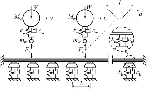
A survey of track models in the frequency range 20–5000 Hz was presented by Knothe and Grassie [Citation111]. It was concluded that improved models were needed to describe more accurately the dynamic and non-linear characteristics of rail pads and ballast/subgrade. For example, the dynamic stiffness of rail pads and ballast/subgrade is known to vary with frequency and with the magnitude of the applied load, but this is ignored in most models. In a vehicle–track interaction model, the dynamic stiffness of railway track components should be used as input rather than the corresponding static stiffness [Citation109].
Wu and Thompson [Citation112] studied the influence of non-linear rail pad and ballast/subgrade stiffness on the dynamic vehicle–track interaction. It was shown that such non-linear features only affect a few rail supports on either side of the wheel load. Yet, it was observed that both impact loads and track vibration levels were noticeably higher for the non-linear track model compared with a linear model, and it was concluded that a linear track model is not sufficient for the prediction of wheel–rail impact.
6.2.4. Impact loading
The calculated influence of train speed and depth of rounded wheel flats on the maximum impact load is illustrated in Figure [Citation96], cf. the experimental results in Figure (b). A three-dimensional non-Hertzian contact model based on Kalker’s variational method was applied. The dynamic vehicle–track interaction was solved with a moving impulse response function (Green’s function) approach [Citation113,Citation114]. As expected, with increasing flat depth, the magnitude of the impact load increases and loss of wheel–rail contact occurs at a lower train speed. The speed dependence is essentially similar for different depths, but the local maximum and minimum of each curve are more pronounced for larger depths and are also shifted to higher speeds. It is observed that the smaller the flat depth, the earlier the curve flattens out at higher train speeds.
Figure 12. Magnitude (including static wheel load 118 kN) of impact load due to a rounded wheel flat as a function of train speed and flat depth. The lines (from lower to upper) correspond to the depths [0.25, 0.50, 0.75, 1.00, 1.25, 1.50, 1.75, 2.00] mm. The maximum of the impact loads from eight simulations with different initial angular positions of the wheel within a sleeper bay is shown. Black circles indicate that loss of contact occurs for at least one of these eight simulations. Three-dimensional non-Hertzian contact model based on Kalker’s variational method. From [Citation96].
![Figure 12. Magnitude (including static wheel load 118 kN) of impact load due to a rounded wheel flat as a function of train speed and flat depth. The lines (from lower to upper) correspond to the depths [0.25, 0.50, 0.75, 1.00, 1.25, 1.50, 1.75, 2.00] mm. The maximum of the impact loads from eight simulations with different initial angular positions of the wheel within a sleeper bay is shown. Black circles indicate that loss of contact occurs for at least one of these eight simulations. Three-dimensional non-Hertzian contact model based on Kalker’s variational method. From [Citation96].](/cms/asset/8052e39f-9d78-4b12-b7f3-77585c3e59ec/nvsd_a_2194544_f0012_ob.jpg)
The influence of contact model on calculated impact loads due to new and rounded wheel flats was investigated by Pieringer et al. [Citation96]. Three-dimensional non-Hertzian contact based on Kalker’s variational method, two-dimensional non-Hertzian contact based on a Winkler bedding of independent springs [Citation103], and non-linear Hertzian point contact were compared. The relative displacement excitation used as input to the Hertzian model was either the deviation in wheel radius from the nominal wheel profile, or the pre-calculated wheel centre trajectory. Both the two-dimensional model and the Hertzian spring model with the wheel centre trajectory as input were found to generate results rather similar with the three-dimensional model. However, the Hertzian model with the wheel profile deviation as input resulted in large differences from the more detailed models. Nevertheless, it was concluded that the correct representation of the longitudinal geometry of the wheel flat has a larger influence on the impact load than the choice of contact model.
A hybrid approach to predict noise due to wheel–rail impact has been presented by Wu and Thompson [Citation60]. In the first step, a time-domain model is applied to calculate the wheel–rail contact force. The time history of the impact load is then transformed to the frequency domain and converted into the form of an equivalent roughness spectrum that can be used as input for the prediction of noise in a conventional frequency-domain model. A similar approach focussing on ground-borne vibration generated by impact loading was presented in [Citation115]. A next step to improve the understanding of wheel–rail impact noise is to develop a time-domain model for the prediction of transient noise, where the non-linear vehicle, track and wheel–rail contact models are extended to be accurate for frequencies up to 5 kHz.
7. Effects of out-of-round wheels
7.1. Effect on wheelsets
Barke and Chiu [Citation4] studied the effect of OOR wheels on vehicle and track components including wheels, bearings, rails, sleepers and ballast. Their work used a boundary element model of the track together with degradation and failure models for each component. Polygonisation of low-order out-of-roundness (up to 4th order) was considered.
Wu et al. [Citation116] looked at the influence of polygonal wear on stresses in axles. A coupled vehicle–track dynamics model was used with non-linear vehicle suspension elements and finite element representations of the slab track and the wheelsets. Axle stress was predicted at various speeds with different amplitudes of measured polygonal wear added. The results demonstrated excitation of a resonance in the axle by the 20th order out-of-roundness, and a consequent significant increase in axle stress from 29.8 to 105 MPa.
Wu et al. [Citation117] generated finite element models of a railway axle and track and used these to assess dynamic stresses induced by polygonal wheels and the effect these stress levels have on the development of fatigue cracks in wheelset axles. Measured accelerations from field tests were used to validate the model. The results indicated that polygonal out-of-roundness can generate high wheel–rail contact forces at typical operation speeds and may contribute to a significant increase in axle stresses. This was used to propose new axle inspection limits.
Wang et al. [Citation118] studied the influence of polygonal wheel wear on axle bearings in a high-speed train. A coupled vehicle–track dynamics model including the axle bearing dynamics was set up. For the case studied, high-order polygonal wear (17th to 21st order) was found to be significant on bearing forces, which more than doubled compared with unworn wheels at a speed of 350 km/h.
Luo et al. [Citation119] examined the case of large longitudinal creep forces due to high traction and braking in mountain railways. The slab track support including fasteners was modelled and the Dahl friction model with non-linear friction including hysteresis was applied. The effects of polygonal wheels on wheel–rail contact conditions and wear were investigated.
7.2. Effect on bogie components
As mentioned in Section 3, wheel polygonisation has become a serious problem in recent years. One impact of this, which has been observed particularly in China, is the fatigue failure of certain bogie components such as the bogie frame, gearbox housing, steel coil spring, etc., see Figures .
Figure 13. (a) Fatigue crack at welding positions at the centre of the cross beam of the bogie frame of a motor bogie [Citation120], (b) fatigue crack at the spring sleeve of one bogie frame of a metro vehicle [Citation122], and (c) fatigue crack at the cross beam of the bogie frame of a metro vehicle [Citation123].
![Figure 13. (a) Fatigue crack at welding positions at the centre of the cross beam of the bogie frame of a motor bogie [Citation120], (b) fatigue crack at the spring sleeve of one bogie frame of a metro vehicle [Citation122], and (c) fatigue crack at the cross beam of the bogie frame of a metro vehicle [Citation123].](/cms/asset/d80a24fa-95ac-4475-81af-784f6af3a70e/nvsd_a_2194544_f0013_oc.jpg)
Figure 14. Fatigue failure of the gearbox housing [Citation125].
![Figure 14. Fatigue failure of the gearbox housing [Citation125].](/cms/asset/1cc8e6fb-2fe3-4a92-b683-60938cb34959/nvsd_a_2194544_f0014_oc.jpg)
Figure 15. Fatigue fracture of the steel coil spring of the primary suspension in (a) a locomotive [Citation128] and (b) a metro train [Citation129].
![Figure 15. Fatigue fracture of the steel coil spring of the primary suspension in (a) a locomotive [Citation128] and (b) a metro train [Citation129].](/cms/asset/a97448df-9a0e-4ef6-87ad-66ec2bfaff56/nvsd_a_2194544_f0015_oc.jpg)
Fu et al. [Citation120] analysed the causes of fatigue cracks in the bogie frame of metro trains. After five years of operation and mileages of over 400,000 km, cracks were found at welded positions at the centre of the cross beam of motor bogie frames. On-track test results indicated that the first two modes of the bogie frame vibration (43.5 Hz and 50.3 Hz, respectively) were excited by rail joints and wheel out-of-roundness. It resulted in equivalent stress amplitudes of up to 96 MPa in the cracked position, which significantly exceeds the fatigue limit (66 MPa) for this type of welded joint. Wang et al. [Citation121] used field tests to study the dynamic stress of fatigue hotspots on the bogie frame of metro trains on one of the metro lines in Beijing. The highest equivalent stress amplitude reached 208 MPa, which is very much higher than the fatigue limit of 70 MPa. Under such conditions, the service life of the bogie frame will decrease significantly. The detailed analysis showed that rail corrugation accompanied with the 8th order wheel out-of-roundness contributed more than 80% of the fatigue damage in the bogie frame. Wang et al. [Citation122] also reported a case of fatigue cracking in the bogie frames of metro trains. A crack was found at the spring sleeve of one bogie frame already at a service mileage of less than 200,000 km. The field test results revealed that the wheels showed serious polygonal wear of the 14th to 16th orders. After wheel re-profiling, the maximum dynamic stress was reduced by 74%, which indicated that the polygonal wheel wear has a significant effect on the fatigue life of the bogie frame. Sun et al. [Citation123] investigated dynamic stresses in a metro bogie frame through field tests and numerical simulations. A crack was found on the cross beam of one bogie frame, see Figure (c). The stress tests showed that the dominating frequency was about 50 Hz under the excitation of wheel out-of-roundness with 5th to 8th orders. Modal testing indicated that an eigenfrequency involving bending of the cross beams combined with torsion of the side beams is 49.5 Hz, which can be easily excited by wheel out-of-roundness and contribute to the fatigue failure of the bogie frame. Based on extensive simulations, they suggested that the wheel should be re-profiled when the wheel radial run-out exceeds 0.5 mm.
The gearbox housing is an important component in the traction system, and its fatigue reliability is greatly important. As mentioned in Section 3, high-order harmonic wear of high-speed train wheels in China has become a serious problem since 2014. It has been noted that when the speed of the EMU is 300 km/h, and the wheels have polygonal wear with a dominating wavelength of approximately 140 mm, the passing frequency of the wheel polygon is close to 580 Hz. Unfortunately, for one type of gearbox housing used on the high-speed EMUs, there is a natural frequency close to 580 Hz. A resonance of the gearbox housing was therefore excited by the wheel polygon, which in turn led to some cases of fatigue failure [Citation124–127], see Figure . Following this study, the shape of the gearbox housing was optimised, to remove natural frequencies in the range of the passing frequencies of the wheel polygon.
Wang et al. [Citation128] studied steel coil spring fracture of the primary suspension of a locomotive, see Figure (a). The modal analysis indicated that the frequency of the first expansion mode of the coil spring is about 93 Hz. Meanwhile, the wheels suffered from serious polygonal wear with a wavelength of 200–250 mm evaluated in 1/3 octave bands. The passing frequencies of such polygonal wheels at normal operating speed of the locomotive are very close to this particular natural frequency causing magnified stresses in the coil spring. A structural optimisation of the coil spring was conducted, and the frequency of the first expansion mode was moved to 107 Hz, which is further away from the passing frequency of the wheel polygon. Compared to the original coil spring, field test results showed that the RMS value of the dynamic stress of the modified coil spring decreased from 38.4 to 12.0 MPa.
Zhang et al. [Citation129] investigated the effect of wheel out-of-roundness on fracture of the steel coil springs in metro vehicles, see Figure (b). The maximum operating speed of the metro train is 120 km/h. The wheels suffered from serious polygonal wear with 12–14 harmonics. A frequency response test and numerical modal analysis showed that the frequencies of the first- and second-order expansion modes of the coil spring are 59 and 113 Hz, respectively. The first-order expansion resonance of the coil spring can be excited when the wheels have polygonal wear and the train speed is close to 40 km/h. Thus, inevitably the train passes through the resonance region of the coil spring during acceleration on leaving a station and deceleration on the approach to a station, which greatly increases the stresses in the coil spring. After wheel re-profiling, the equivalent stress amplitude decreased from 64.1 to 15.0 MPa. Based on the relationship between wheel out-of-roundness and statistics of coil spring fractures, a closely controlled wheel re-profiling strategy has been recommended to reduce spring fracture.
Wheel out-of-roundness can induce periodic wheel–rail impacts and subject bogie components to periodically alternating loads. From the several cases surveyed above, it can be concluded that wheel out-of-roundness, especially wheel polygonisation, has a significant influence on the fatigue reliability of bogie components. The excitation frequencies of polygonal wheels change with the speed of the rolling stock. When any of the passing frequencies of the OOR wheel is close to a natural mode frequency of a bogie component, this can result in intense vibration. Therefore, it is particularly important to monitor wheel out-of-roundness and repair it in time.
7.3. Effect on track / subgrade
Chen et al. [Citation130] published work on the effect of polygonal wear on the subgrade in high-speed lines. A hybrid model was used including a 3D finite element model of a Chinese CRTS-II double block slab track and a multibody dynamics model of the vehicle with the forces due to measured polygonal wear superimposed at the wheel–rail interface in the model. High-frequency excitations corresponding to the 23rd and 24th order out-of-roundness were found to lead to momentary wheel unloadings and significant increases in vertical wheel–rail contact forces, fastener forces and rail accelerations. Lower orders of out-of-roundness were found to have a large influence on the vertical acceleration of the slab and consequent stresses in the slab material.
Kang et al. [Citation131] studied the effect of polygonal wheel wear on the fatigue failure of rail fastening clips. A finite element model of the wheelset and rail including the fastening system was set up. The effects of unworn wheels and wheels with 24th order out-of-roundness were compared. Severe vibrations at 586 and 1172 Hz were predicted at vehicle speed 237 km/h, where 586 Hz is close to the lowest resonance frequency of the fastening clip. It was predicted that amplitudes of the 24th order out-of-roundness higher than 0.15 mm results in the initiation of cracks in the fastening.
Bethel Lulu et al. [Citation132] looked at the influence of OOR wheels on rail welds. Again, a finite element model of the track was used, where the rails were modelled as Euler-Bernoulli beams discretely supported by springs and dampers. A multibody model of a Chinese locomotive with flexible wheelsets was used including the first 60 modes of wheelset vibration. A sinusoidal vertical rail irregularity was used to represent a welded joint over a length of 1 m. Wheel out-of-roundness of the 20th order was shown to create high vertical wheel–rail contact forces resulting in peak forces at various frequencies between 122 and 235 Hz, which were close to eigenfrequencies of the wheelset.
Yin et al. [Citation133] studied the impact of polygonal wear on rail corrugation with the vertical wheel–rail contact force being treated as a prescribed harmonic load approximated by the summation of several sine waves. The wear on the inner rail in a curve, represented by an Euler-Bernoulli beam, was simulated using a frictional work wear model. Corrugation was shown to be initiated and potentially to grow at a wavelength corresponding to the order of the wheel out-of-roundness.
7.4. Effects on wheel–rail contact and vehicle dynamics
Wu et al. [Citation134] used a coupled vehicle–track interaction model to simulate the dynamic behaviour of a high-speed railway vehicle, with measured out-of-roundness idealised as a prescribed harmonic relative displacement at the wheel–rail contact. Accelerations in the axle box and bending stresses in the axle were analysed. The results showed that OOR wheels in high-speed operations can lead to substantially higher magnitudes of vertical wheel–rail contact force and potentially wheel lift. At 300 km/h, the peak accelerations in the axle boxes occurring near 562 Hz were linked to a rail bending mode.
Zhu et al. [Citation135] investigated the effect of asymmetric out-of-roundness on subway train wheels. This was modelled using measured wheel out-of-roundness and a vehicle dynamics model. They found that asymmetric out-of-roundness (different amplitudes on the wheels on the same axle) had a greater effect on peak vertical vibration levels than with symmetrically out-of-round wheels, and also potentially influencing the stability of the vehicle.
Yang et al. [Citation136] used a detailed multibody model with multiple vehicles including a heavy haul locomotive. Measured wheel out-of-roundness was applied to induce varying normal loads in the wheel–rail contact. The results were validated against measured accelerations of the axle box, bogie frame and locomotive body and showed that wheel out-of-roundness influences the lateral and longitudinal vibrations of the system as well as the vertical. In some cases, these accelerations were high enough to trigger the axle box bearing vibration alarm.
Liang et al. [Citation137] looked at heavy haul locomotives in China and found levels of out-of-roundness with amplitudes of radial run-out of up to 0.87 mm, which is close to the safety limit 1 mm in terms of wheel repair interval. The wheels were mainly polygonal with 1–3 orders, but 6–8 orders were also reported as common. The work showed that tractive effort was likely to be reduced by such out-of-roundness levels due to their effect on vertical wheel–rail contact forces especially in wet conditions and could cause wheel sliding. In the worst cases, peak vertical forces were found to be increased by 55 kN due to the out-of-roundness with corresponding increases in normal stresses by 240 MPa and tangential stresses by 470 MPa.
Jiang et al. [Citation138] reported a case of deteriorating ride comfort in metro vehicles. Field test results showed the occurrence of abnormal car body vibrations at a frequency around 10 Hz when the train was running on floating slab track. A 3D metro vehicle and floating slab track coupled model was established to study the mechanism of this vibration. They found that the frequency of the first-order vertical bending mode of the floating slab is about 10 Hz, and the wheels exhibited serious OOR wear. At a specific vehicle speed, the passing frequency of the wheel eccentricity is close to 10 Hz, which caused a resonance of the vehicle and the floating slab track. Wang et al. [Citation139] investigated the abnormal vibration of metro trains through field experiments. They found that the first-order vertical bending and twisting modes of the car body can be excited by low-order wheel out-of-roundness, which greatly deteriorates ride comfort. After wheel re-profiling, the ride comfort could be improved by 35–40%. Based on long-term monitoring tests from the aspects of running mileage and the maximum value of the radial run-out, wheel re-profiling strategies were proposed to eliminate the abnormal vibration.
Tao et al. [Citation140] examined the case of metro train wheels using the multibody simulation software Simpack and the finite element software ANSYS. The model included the flexibilities of the wheelset and bogie frame as well as the rail and track support structure. High- and low-order out-of-roundness were investigated and the P2 resonance and axle bending modes were shown to be excited at normal operating speeds. The modelling also showed that polygonisation on one wheelset could initiate polygonisation on other wheelsets in the vehicle.
8. Operation aspects
8.1. Wheel polygonisation on high-speed trains in China
Since the first high-speed passenger railway was put into operation in 2008, the total mileage of high-speed railway lines in China has extended to over 40,000 km. In the early stage of this expansion (2008–2013), OOR wheels of high-speed trains showed slight low-order polygonisation and non-periodic out-of-roundness, which had little influence on the high-speed train operation. However, high-order periodic wear of high-speed wheels has become a serious problem in China since 2014 and this has caused many fatigue failure problems of vehicle and track components, and increasing serious interior noise issues. Many important experiences and achievements have been made in solving problems caused by polygonal wheels in high-speed operations in China.
Wheel re-profiling is the main countermeasure which is initially considered. Based on extensive field tests and long-term monitoring, maintenance criteria for wheel polygons to mitigate interior noise have been proposed. Moreover, to ensure the fatigue reliability of vehicle components, a limit for high-order polygonal wheels has also been proposed. After implementing these strict maintenance criteria, the failures of vehicle components and problems with interior noise have been significantly reduced. In addition, some test results show that the initial or residual wheel irregularities after wheel re-profiling have a significant influence on the formation and development of wheel polygonal wear. Therefore, the wheel roughness levels after re-profiling are also strictly controlled. As a result of the use of upgraded underfloor wheel lathes, as mentioned in Section 5.1, it is now possible to measure wheel roughness levels after wheel re-profiling, so that these strict criteria can be implemented.
Although there is no consensus on the exact formation mechanism of high-speed train polygonal wheels in China, researchers and engineers generally agree that the polygonal wheels on a high-speed train are caused by a frequency-fixing mechanism. According to the features of wheel polygon evolution and results from simulations of dynamic vehicle–track interaction, an ‘Integral Multiple Condition’ parameter was derived [Citation41]. It is defined as the ratio between the wheel circumference and the wavelength of the polygon. Taking one type of high-speed train as an example, the identified frequency related to the formation of wheel polygon is approximately 580 Hz. At a dominant running speed of 300 km/h, this would correspond to a wavelength of the formed wheel polygon of about 144 mm. If the ‘Integral Multiple Condition’ parameter is close to an integer, this serves as an indication that the risk of forming a wheel polygon is high. Because the wheel diameter is gradually decreased by wheel wear and wheel re-profilings, the ‘Integral Multiple Condition’ could be satisfied several times within the life cycle of the wheels, see Figure . Therefore, when the wheel diameter is close to the ‘Integral Multiple Condition’, the interval between wheel re-profilings must be shortened.
Figure 16. Polygonal wear development at different operation speeds and different wheel diameters. The highlighted red points mean there is a rapid development of polygonal wheel wear according to the ‘Integral Multiple Condition’ [Citation41].
![Figure 16. Polygonal wear development at different operation speeds and different wheel diameters. The highlighted red points mean there is a rapid development of polygonal wheel wear according to the ‘Integral Multiple Condition’ [Citation41].](/cms/asset/4b3671e9-5614-4120-9444-1b79ed6b4522/nvsd_a_2194544_f0016_oc.jpg)
On the other hand, on a given high-speed railway line, the operation mode and running speed are relatively fixed. This provides favourable conditions for the formation of wheel polygonal wear. Therefore, arranging for trains to operate on different high-speed railway lines can greatly slow down the formation of polygonal wheels. Figure shows an example of polygonal wheel wear for the same high-speed EMU running on two different lines. In the beginning, the train was running on a new line not yet in commercial operation where the train operated at a constant speed of 250 km/h during the operation assessment tests. Polygonal wheel wear was already very significant after running 150,000 km. After wheel re-profiling, the train was operated on an intercity commercial line, where the speed of operation varied widely. Then, the polygonal wheel wear no longer appeared. The same conclusion was also verified on locomotive wheels [Citation11].
Figure 17. Measured wheel polygonisation on all the wheels on the same high-speed train running on two different high-speed railway lines [Citation42].
![Figure 17. Measured wheel polygonisation on all the wheels on the same high-speed train running on two different high-speed railway lines [Citation42].](/cms/asset/1916ac8a-d8ba-469c-a609-ed24bbf5e3de/nvsd_a_2194544_f0017_oc.jpg)
Researchers and engineers in China have made great efforts to solve the problem of polygonal wheel wear and tried many measures. Among these measures, the use of abrasive blocks is the most effective one, which is now required equipment for the Fuxing series EMUs. Figure illustrates long-term monitoring results for wheel roughness levels. The maximum value of roughness level for the orders 10–30 was used to evaluate the effect of the abrasive block on the suppression of polygonal wheel wear. In this case, there were no abrasive blocks installed on the train before the third wheel re-profiling. It is observed that roughness levels increased gradually with increasing running mileage, especially in the first and second wheel re-profiling intervals, and that the highest roughness level was about 25 dB re 1 µm before the second wheel re-profiling. After the second re-profiling, the train was operated on different high-speed railway lines. Therefore, polygonal wheel wear was moderate. After the third re-profiling, all the wheels were equipped with abrasive blocks. The wheel roughness levels then remained at very low levels, and the maximum roughness level was only 9.5 dB re 1 µm after running about 400,000 km. Wang et al. [Citation141] reported some interesting results from field tests on the influence of abrasive blocks on wheel wear and RCF. They found that proper use of abrasive blocks can keep the wheel tread wear at normal levels and eliminate wheel polygonal wear and RCF cracks on the wheel tread.
Figure 18. Evolution of the maximum value of roughness level in range of 10th to 30th orders [Citation39]. (Each asterisk in this figure presents the measurement result of one wheel).
![Figure 18. Evolution of the maximum value of roughness level in range of 10th to 30th orders [Citation39]. (Each asterisk in this figure presents the measurement result of one wheel).](/cms/asset/41ca4f38-41a3-409f-9b67-e168686e1282/nvsd_a_2194544_f0018_oc.jpg)
8.2. International approach to wheel impact load detectors and alarm limits
To mitigate wheel–rail impact loading, the main priority should be to control and monitor the development of discrete wheel tread irregularities by design and regular maintenance. Wheel impact load detectors (WILD) are used to detect wheels generating high levels of vertical dynamic wheel–rail contact force (see section 5.2). The measured force levels provide operators with information on the status of their wheel fleet. In the case of RCF damage, these levels can be used to schedule preventive maintenance action before the wheel out-of-roundness grows to unacceptable levels, while wheels with flats can be taken out of service for corrective maintenance.
Various types of sensors have been deployed in commercial wayside WILD systems to measure vertical dynamic wheel–rail contact force:
Strain gauge load circuits mounted on the neutral axis of the rail in between two adjacent sleepers in several consecutive sleeper bays. Based on the measured shear force at two rail cross-sections, the vertical wheel–rail contact force is determined from a static equilibrium (the influence of the rail inertia is neglected). The resolution of the system has been reported to be 445 N for train speeds in the interval 50–300 km/h [Citation142].
Load cells for measurement of rail seat loads on a number of sleepers (‘high-precision concrete weighing ties’). The signals are processed for a diagnosis of wheel imperfections [Citation143].
Fibre optic sensing technology for measurement of rail bending moment. A diagnosis tool is used to process the maximum and root mean square values of the signals, to determine the static and dynamic wheel loads, and to indicate the type of wheel damage [Citation144].
Accelerometers mounted on the rail. However, the measured acceleration does not provide a quantitative measure of the magnitude of the impact load.
WILD systems are typically placed on tangent track with concrete sleepers on premium ballast and well-compacted subgrade to reduce sources of load variation due to irregularities in track geometry and sleeper support conditions [Citation145]. Regular track maintenance and calibration of the detectors are key for accurate measurements.
The implementation of a WILD offers the opportunity to define criteria for removal of wheels that are based on the measured impact load rather than a visual inspection of the wheel tread irregularity. This is useful since the magnitude of the impact load is generally more influenced by the depth of the irregularity rather than its length. Besides the measured mean loads for the left and right wheels, the peak loads and the dynamic loads (mean load subtracted from peak load) are recorded for each passing wheelset. Further, the ratio between peak load and mean load is a useful measure for detecting OOR wheels on vehicles in tare conditions (low axle loads).
For a given wheel tread irregularity, it should be noted that the measured impact load depends on the lateral position of the wheel–rail contact (rolling circle) relative to the position of the tread defect, as well as on the impact position along the detector due to the longitudinal variation in track stiffness in a ballasted track on discrete sleeper supports. In addition, the measured impact load depends on train speed and the dynamics of the coupled vehicle–track system. Altogether, this means that a given wheel tread irregularity in similar operating conditions is likely to generate different impact loads in two adjacent WILDs, or even in the same WILD on two different occasions. It has been observed that the scatter in measured impact loads increases with increasing train speed.
To prevent unacceptable deterioration levels and safety-related failures, alarm limits are prescribed. The UIC recommended alarm limit for peak load mandates an immediate stop of the train if the peak wheel–rail contact force exceeds 350 kN, with an alert level at 300 kN [Citation146]. A summary of sensor technologies and alarm levels applied by infrastructure managers in selected countries is reported in Table . Another survey from 2009 was presented in [Citation147]. If a wheel load limit is exceeded, the required action is generally a train speed restriction until the vehicle with the OOR wheel has been removed from the train. The significant variation in alarm limits observed in Table indicates that a harmonisation of alarm limits would make cross-border traffic more efficient [Citation146]. For continuously welded rails in areas with particularly cold winters, an alarm limit that is dependent on temperature relative to stress-free temperature could be advisable [Citation146]. The specified alarm limit should provide a balance between preventing operational failures and minimising the number of stopped trains. Understanding the influence of wheel impact loads on the risk for vehicle and track damage is the scientific basis for such optimised alarm limits [Citation61,Citation145,Citation148,Citation149].
Table 2. Sensor technologies (see descriptions above) and alarm limits applied in selected countries.
9. Mitigation methods
Up to now the main mitigation method used by railway operators when polygonal wheel wear has been detected has been reprofiling of the wheels. Modern wheel lathes are fitted with systems that allow polygonal out-of-roundness to be detected even at low levels and data from wayside or vehicle mounted systems may also be available, see Section 5. Some operators have introduced criteria for the maximum allowable polygonal out-of-roundness, e.g. that based on interior noise that has been introduced in China, see Section 8.1. Wheel impact load detectors can be used to identify wheels generating high levels of vertical dynamic wheel–rail contact force. Measured force levels can be used to schedule preventive maintenance action before the wheel out-of-roundness due to RCF grows to unacceptable levels, while wheels with flats can be taken out of service for corrective maintenance. Different alarm limits have been set in different countries, see Section 8.2 for a review of these.
In order to control polygonisation the use of abrasive blocks has been found to be effective and this is now standard equipment on some EMUs in China, see Section 8.1. This also has the advantage of controlling RCF on the wheels. Where polygonisation is being caused by track features, mitigation methods may require changes to track support methods/components or changes to track maintenance procedures.
Changes to the structural design of the bogie frame have resulted in reductions in wheel polygonisation, see Section 7.2. Although difficult to introduce in existing fleets, this may be an important consideration at the design stage for a vehicle and the computer tools reported here have the potential to assist designers. Several researchers have reported significant reductions in polygonisation after changes to bogie frame or gearbox construction or changes in suspension components.
Operational changes have been found to significantly affect the growth of out-of-round wheels. In particular, polygonisation has been seen to occur rapidly on vehicles running on limited routes and at highly controlled speeds, for example on some new high-speed lines or on systems where automatic train operation is employed (see Section 8.1). Although not always possible for operators, one mitigation measure may be to alternate the diagrams/routes that vehicles follow.
Finally, recent research has considered the role of the traction or braking control systems and it may be that changes in the algorithms within these systems could reduce the potential for initiation of polygonisation. This is ongoing research.
10. Conclusions
Out-of-round railway wheels cause significant problems to railway operators around the world. The problem seems to be growing and the exact mechanisms are not fully understood and appear to be different in different systems. Damage caused by out-of-round wheels includes fatigue and failure of vehicle components and damage to track and subgrade. A lot of effort has been spent by groups in industry and universities around the world in trying to quantify, understand and to solve these problems and their work is reviewed in this paper.
Polygonisation has been widely observed and occurs on a wide range of systems including high-speed, commuter, metro and freight vehicles and on locomotives. Polygonal wheels have out-of-roundness wavelengths varying from 10 cm to over 3 m corresponding to high-order polygonal out-of-roundness down to lower order or eccentricity. Amplitudes of out-of-roundness can reach over 1 mm for the lower order irregularities. Measurement of wheel out-of-roundness has improved and many systems are now used including wayside systems or onboard vehicles or by wheel-lathes during reprofiling. Many railway operators have set alarm limits for out-of-roundness linked to measurement systems and these has been reviewed in this paper.
Polygonisation is clearly linked to wear at the wheel surface but linked to a wavelength or frequency-fixing mechanism. Researchers have used computer simulation tools to investigate this mechanism and have linked it variously to Wheelset bending or torsional oscillations; Bogie or traction system resonances; Interaction of traction or braking controllers; Wheel–rail stick–slip vibration and Local rail bending.
Mitigation measures include reprofiling, redesign of key components including wheels, axles, bogie or transmission structures, traction or braking controllers. Operations where vehicles and speeds are mixed seem to be less prone to polygonisation.
Disclosure statement
No potential conflict of interest was reported by the author(s).
Additional information
Funding
References
- Nielsen JCO, Johansson A. Out-of-round railway wheels – a literature survey. Proc Inst Mech Eng Part F J Rail Rapid Transit. 2000;214:79–91.
- Nielsen JCO, Lundén R, Johansson A, et al. Train-track interaction and mechanisms of irregular wear on wheel and rail surfaces. Veh Syst Dyn. 2003;40(1–3):3–54.
- Nielsen JCO, Pieringer A, Thompson DJ, et al. Wheel–rail impact loads, noise and vibration: a review of excitation mechanisms, prediction methods and mitigation measures. In: G Degrande et al., editors, Noise and vibration mitigation for rail transportation systems (Proceedings of the 13th International Workshop on Railway Noise (IWRN13), Ghent, Belgium, September 2019), Notes on Numerical Fluid Mechanics and Multidisciplinary Design, Vol. 150; 2021. p. 3–40.
- Barke DW, Chiu WK. A review of the effects of out-of-round wheels on track and vehicle components. Proc Inst Mech Eng Part F J Rail Rapid Transit. 2005;219(3):151–175.
- Tao G, Wen Z, Jin X, et al. Polygonisation of railway wheels: a critical review. Rail Eng Science. 2020;28(4):317–345.
- Nielsen JCO, Mirza A, Cervello S, et al. Train induced ground vibration – optimised rolling stock mitigation measures and their parameters. RIVAS (SCP0- GA-2010-265754): Deliverable 5.4, 2013 Feb.
- Tao G, Wang L, Wen Z, et al. Measurement and assessment of out-of-round electric locomotive wheels. Proc Inst Mech Eng Part F J Rail Rapid Transit. 2018;232(1):275–287.
- Yang Y, Ling L, Liu P, et al. Experimental investigation of essential feature of polygonal wear of locomotive wheels. Measurement. 2020;166:108199.
- Tao G, Wang L, Wen Z, et al. Experimental investigation into the mechanism of the polygonal wear of electric locomotive wheels. Veh Syst Dyn. 2018;56(6):883–899.
- Tao G, Liu X, Wen Z, et al. Formation process, key influencing factors, and countermeasures of high-order polygonal wear of locomotive wheels. J Zhejiang Univ-Sci A (Appl Phys & Eng). 2021;21(1):70–84.
- Yang Y. An investigation on the evolution of polygonal wear of locomotive wheels and its countermeasures. Chengdu: Doctoral thesis of Southwest Jiaotong University; 2022; in Chinese.
- Tao G, Wen Z, Chen G, et al. Locomotive wheel polygonisation due to discrete irregularities: simulation and mechanism. Veh Syst Dyn. 2021;59(6):872–889.
- Tao G. Investigation into the formation mechanism of the polygonal wear of HXD electric locomotive wheels. Chengdu: Doctoral thesis of Southwest Jiaotong University; 2018; in Chinese.
- Yang Y, Xu M, Ling L, et al. Polygonal wear evolution of locomotive wheels subjected to anti-slip control. Wear. 2022;500–501:204348.
- Fröhling R, Spangenberg U, Reitmann E. Root cause analysis of locomotive wheel tread polygonisation. Wear. 2019;432–433:102911.
- Spangenberg U. Variable frequency drive harmonics and interharmonics exciting axle torsional vibration resulting in railway wheel polygonisation. Veh Syst Dyn. 2020;58(3):404–424.
- Spangenberg U, Fröhling R. Solving locomotive wheel polygonisation by reducing variable frequency drive interharmonics. Proc Inst Mech Eng Part F J Rail Rapid Transit. 2021;235(1):73–82.
- Johansson A, Andersson C. Out-of-round railway wheels – A study of wheel polygonalization through simulation of three-dimensional wheel–rail interaction and wear. Veh Syst Dyn. 2005;43(8):539–559.
- Jin X, Tao G, Zhao X, et al. Wear and RCF problems of metro wheel/rail systems: phenomena, causes and countermeasures in China. In: Proceedings of CM2022; 2022.
- Jin X, Wu L, Fang J, et al. An investigation into the mechanism of the polygonal wear of metro train wheels and its effect on the dynamic behaviour of a wheel/rail system. Veh Syst Dyn. 2012;50(12):1817–1834.
- Chen G, Jin X, Wu P, et al. Finite element study on the generation mechanism of polygonal wear of railway wheels. Journal of the China Railway Society. 2011;33(1):14–18. in Chinese.
- Ma W, Song R, Luo S. Study on the mechanism of the formation of polygon-shaped wheels on subway vehicles. Proc Inst Mech Eng Part F J Rail Rapid Transit. 2016;230(1):129–137.
- Fu B, Bruni S, Luo S. Study on wheel polygonization of a metro vehicle based on polygonal wear simulation. Wear. 2019;438–439:203071.
- Tao G, Wen Z, Liang X, et al. An investigation into the mechanism of the out-of-round wheels of metro train and its mitigation measures. Veh Syst Dyn. 2019;57(1):1–16.
- Cai W, Chi M, Tao G, et al. Experimental and numerical investigation into formation of metro wheel polygonalization. Shock Vib. 2019;2019:1538273.
- Mu J, Zeng J, Huang C, et al. Experimental and numerical investigation into development mechanism of metro wheel polygonalization. Eng Fail Anal. 2022;136:106152.
- Yang X, Tao G, We L, et al. On the formation mechanism of high-order polygonal wear of metro train wheels: experiment and simulation. Eng Fail Anal. 2021;127:105512.
- Tao G, Xie C, Wang H, et al. An investigation into the mechanism of high-order polygonal wear of metro train wheels and its mitigation measures. Veh Syst Dyn. 2021;59(10):1557–1572.
- Yang X, Tao G, Wen Z. Causes and evolution of asymmetric polygonal wear of metro train wheelset. In: Proceedings of CM2022; 2022. p. 682–691.
- Kang X, Chen G, Zhu Q, et al. Study on wheel polygonal wear of metro trains caused by frictional self-excited oscillation. Triboly Transs. 2021;64(6):1108–1117.
- Lulu GB, Chen R, Wang P, et al. Random vibration analysis of tram-track interaction on a curve due to the polygonal wheel and track irregularity. Veh Syst Dyn. 2022;60(14):1125–1147.
- Shi M, Li W, Wu M, et al. Analysis of out-of-round wheels and the effect of wheel polygonalization on vehicle vibration. In: Proceedings of the 11th International Conference on Contact Mechanics and Wear of Rail/Wheel Systems (CM2018), Delft, The Netherlands; 2018. p. 856–861.
- Staskiewicz T, Firlik B, Kominowski J. Out of round tram wheels – multibody simulation study based on measured wheel rim geometry. Proc Inst Mech Eng Part F J Rail Rapid Transit. 2022;236(1):122–133.
- Zehetbauer F, Edelmann J, Plöchl M, et al. Study on potential evolution mechanisms of OOR wheels at trams. In: The IAVSD International Symposium on Dynamics of Vehicles on Roads and Tracks. New York: Springer; 2022. p. 572–581.
- Zehetbauer F, Edelmann J, Plöechl M. A minimal model to study self-excited vibrations of a tram wheelset in curves with small radius of curvature. Veh Syst Dyn. 2023. DOI:10.1080/00423114.2022.2139728.
- Kurzeck B, Hecht M. Dynamic simulation of friction-induced vibrations in a light railway bogie while curving compared with measurement results. Veh Syst Dyn. 2010;48(Suppl.):121–138.
- Rode W, Müller D, Villman J. Results of DB AG investigations – out-of-round wheels. In: Proceedings Corrugation Symposium – Extended Abstracts, IFV Bahntechnik, Technische Universität Berlin, Berlin, Germany; 1997.
- Morys B. Enlargement of out-of-round wheel profiles on high speed trains. J Sound Vib. 1999;227(5):965–978.
- Wang P, Tao G, Yang X, et al. Analysis of polygonal wear characteristics of Chinese high-speed train wheels. J Southwest Jiaotong Univ; 2021. Available from: https://kns.cnki.net/kcms/detail/51.1277.U.20211124.1532.002.html (in Chinese)
- Wu Y, Du X, Zhang H, et al. Experimental analysis of the mechanism of high-order polygonal wear of wheels of a high speed train. J Zhejiang Univ-Sci A (Appl Phys & Eng). 2017;18(8):579–592.
- Wu Y, Jin X, Cai W, et al. Key factors of the initiation and development of polygonal wear in the wheels of a high-speed train. Appl Sci. 2020;10:5880.
- Wu Y, Wang J, Liu M, et al. Polygonal wear mechanism of high-speed wheels based on full-size wheel–rail roller test rig. Wear. 2022;494–495:204234.
- Dai H, Li D, Zhuang S. Study on the mechanism of high order out of round and wear of high-speed railway train’s wheel. In: Proceedings of 25th International Symposium of the International Association of Vehicle System Dynamics on Dynamics of Vehicles on Roads and Tracks; 2017.
- Qu S, Zhu B, Zeng J, et al. Experimental investigation for wheel polygonisation of high-speed trains. Veh Syst Dyn. 2021;59(10):1573–1586.
- Wu X, Rakheja S, Cai W, et al. A study of formation of high order wheel polygonalization. Wear. 2019;424–425:1–14.
- Cai W, Chi M, Wu X, et al. Experimental and numerical analysis of the polygonal wear of high-speed trains. Wear. 2019;440–441:203079.
- Cai W, Wu X, Chi M, et al. Wheel polygonisation growth due to multiple wheelsets/track coupling vibration. Veh Syst Dyn. 2023;61(1):177–199.
- Cai W, Wu X, Chi M, et al. High-order wheel polygonal wear growth and mitigation: a parametric study. Mech Syst Signal Proc. 2023;186:109917.
- Peng B, Iwnicki S, Shackleton P, et al. General conditions for railway wheel polygonal wear to evolve. Veh Syst Dyn. 2021;59(4):568–587.
- Ma C, Gao L, Cui R, et al. The initiation mechanism and distribution rule of wheel high-order polygonal wear on high-speed railway. Eng Fail Anal. 2021;119:104937.
- Kang X, Chen G, Song Q, et al. Effect of wheelset eccentricity on the out-of-round wheel of high-speed trains. Eng Fail Anal. 2022;131:105816.
- Wu B, Qiao Q, Chen G, et al. Effect of the unstable vibration of the disc brake system of high-speed trains on wheel polygonalization. Proc Inst Mech Eng Part F J Rail Rapid Transit. 2020;234(1):80–95.
- Wu B, Shang Z, Pan J, et al. Analysis on the formation cause for the high-order wheel polygonization of the high-speed trains based on the finite element method. Veh Syst Dyn. 2023;61(1):1–18.
- Zhao XN, Chen GX, Huang ZY, et al. Study on the different effects of power and trailer wheelsets on wheel polygonal wear. Shock Vib. 2020;2020:2587152.
- Zhao XN, Chen GX, Lv JZ, et al. Study on the mechanism for the wheel polygonal wear of high-speed trains in terms of the frictional self-excited vibration theory. Wear. 2019;426–427:1820–1827.
- Chen Z, Zhi Y, Wang K, et al. Effect of drive and transmission system on wheel polygonal wear of an heavy-haul locomotive. Veh Syst Dyn. 2022. DOI:10.1080/00423114.2022.2153066.
- Deuce R. Wheel tread damage – an elementary guide [Technical report]. Bombardier Transportation GmbH, Netphen, Germany; 2007, 38pp.
- Ekberg A, Åkesson B, Kabo E. Wheel/rail rolling contact fatigue – probe, predict, prevent. Wear. 2014;314:2–12.
- Jergéus J. Railway wheel flats – Martensite formation, residual stresses and crack propagation [PhD thesis]. Department of Solid Mechanics, Chalmers University of Technology, Gothenburg, Sweden; 1998.
- Wu TX, Thompson DJ. A hybrid model for the noise generation due to railway wheel flats. J Sound Vib. 2002;251(1):115–139.
- Nielsen JCO, Abrahamsson TJS, Ekberg A. Probability of instant rail break induced by wheel–rail impact loading using field test data. Int J Rail Transp. 2022;10(1):1–23.
- Jenkins HH, Stephenson JE, Clayton GA, et al. The effect of track and vehicle parameters on wheel/rail vertical dynamic forces. Rail Eng J. 1974;3(1):2–16.
- Nielsen JCO, Mirza A, Cervello S, et al. Reducing train-induced ground-borne vibration by vehicle design and maintenance. Int J Rail Transp. 2015;3(1):17–39.
- Alemi A, Corman F, Lodewijks G. Condition monitoring approaches for the detection of railway wheel defects. Proc Inst Mech Eng Part F J Rail Rapid Transit. 2017;231(8):961–981.
- Cai W, Chi M, Wu X, et al. A long-term tracking test of high-speed train with wheel polygonal wear. Veh Syst Dyn. 2021;59(11):1735–1758.
- Johansson A. Out-of-round railway wheels – assessment of wheel tread irregularities in train traffic. J Sound Vib. 2006;293(3–5):795–806.
- Liu F, Liang L, Xu G, et al. On-machine measurement and evaluation for turned wheel profile of rail vehicle. IEEE T Ins Meas. 2021;70:1002511.
- Johansson A, Nielsen JCO. Out-of-round railway wheels – wheel–rail contact forces and track response derived from field tests and numerical simulations. Proc Inst Mech Eng Part F J Rail Rapid Transit. 2003;217(2):136–146.
- Reitmann E, Fröhling R, Hettasch G. Identification and monitoring of polygonised railway wheels using existing wheel impact monitoring measurement data. In: Proceedings of the 11th International Heavy Haul Association Conference (IHHA 2017), Cape Town, South Africa, 2–6 September 2017. p. 826–833.
- Alemi A, Corman F, Pang Y, et al. Reconstruction of an informative railway wheel defect signal from wheel–rail contact signals measured by multiple wayside sensors. Proc Inst Mech Eng Part F J Rail Rapid Transit. 2019;233(1):49–62.
- China Academy of Railway Sciences, Locomotive & Car Research Institute of China Academy of Railway Sciences, Railway Engineering Research Institute of China Academy of Railway Sciences, et al. Fully continuous ground measurement method and system for wheel rail vertical force. Australia, AU2015392675; 2015.
- Li X, Zeng Y, Li F, et al. Compound measuring zone method for continuous measurement of wheel/rail vertical force on ground. China Rail Sci. 2019;45(5):87–94. in Chinese.
- Sun Q, Chen C, Kemp AH, et al. An on-board detection framework for polygon wear of railway wheel based on vibration acceleration of axle-box. Mech Syst Signal Proc. 2021;153:107540.
- Chen S, Wang K, Zhou Z, et al. Quantitative detection of locomotive wheel polygonization under non-stationary conditions by adaptive chirp mode decomposition. Rail. Eng. Science. 2022;30(2):129–147.
- Wang Q, Xiao Z, Zhou J, et al. A dynamic detection method for polygonal wear of railway wheel based on parametric power spectral estimation. Veh Syst Dyn. 2022. DOI:10.1080/00423114.2022.2117058.
- Wang Q, Xiao Z, Zhou J, et al. A new DFT-based dynamic detection framework for polygonal wear state of railway wheel. Veh Syst Dyn. 2022. DOI:10.1080/00423114.2022.2100797.
- Ye Y, Zhu B, Huang P, et al. OORNet: A deep learning model for on-board condition monitoring and fault diagnosis of out-of-round wheels of high-speed trains. Measurement. 2022;199:111268.
- Newton SG, Clarke RA. An investigation into the dynamic effects on the track of wheelflats on railway vehicles. J Mech Eng Sci. 1979;21(4):287–297.
- Fermér M, Nielsen JCO. Wheel/rail contact forces for flexible versus solid wheels due to tread irregularities. Veh Syst Dyn. 1994;23(S1):142–157.
- Fermér M, Nielsen JCO. Vertical interaction between train and track with soft and stiff railpads – full-scale experiments and theory. Proc Inst Mech Eng Part F J Rail Rapid Transit. 1995;209:39–47.
- Dukkipati RV, Dong R. Impact loads due to wheel flats and shells. Veh Syst Dyn. 1999;31:1–22.
- Gullers P, Andersson L, Lundén R. High-frequency vertical wheel–rail contact forces – field measurements and influence of track irregularities. Wear. 2008;265:1472–1478.
- Kalay S, Tajaddini A, Reinschmidt A, et al. Development of performance-based wheel-removal criteria for North American railroads. In: Proceedings of the 11th International Wheelset Congress, Paris, France, 18–22 June 1995. p. 227–233.
- Asplund M, Söderström P. Field validation of force response from defective wheel. In: Proceedings of the 12th International Conference on Contact Mechanics and Wear of Rail/Wheel Systems (CM2022), Melbourne, Australia, 4–7 September 2022, 5pp.
- Ahlbeck DR. A study of dynamic impact load effects due to railroad wheel profile roughness. Proceedings of 10th IAVSD Symposium Prague, August 1987. p. 13–16.
- Meinke P, Meinke S. Polygonalization of wheel treads caused by static and dynamic imbalances. J Sound Vib. 1999;227(5):979–986.
- Soua B, Pascal JP. Computation of 3D wear of the wheels in a high speed bogie [Report INRETS-LTN]. Arcueil, France; 1995.
- Meywerk M. Polygonalization of railway wheels. Arch Appl Mech. 1999;69(2):105–120.
- Liu X, Zhai W. Analysis of vertical dynamic wheel/rail interaction caused by polygonal wheels on high speed trains. Wear. 2014;314:282–290.
- Bogacz R, Frischmuth K. On the dynamic effects of wheel–rail interaction in the case of polygonalisation. Mech Syst Signal Proc. 2016;79:166–173.
- Peng B, Iwnicki SD, Shackleton P, et al. Comparison of wear models for simulation of railway wheel polygonisation. Wear. 2019;436–437:203010.
- Cui D, Zhang X, Wang R, et al. The effect of 3D wear state of wheel polygon on wheel–rail system dynamics. Veh Syst Dyn. 2022;60(9):3109–3126.
- Fu Y, Cui D, Liu T, et al. Research on the prediction method for the three-dimensional wear state of the polygon wheel. Veh Syst Dyn. 2022. DOI:10.1080/00423114.2022.2053172.
- Steenbergen MJMM. The role of the contact geometry in wheel–rail impact due to wheel flats. Veh Syst Dyn. 2007;45(12):1097–1116.
- Remington PJ, Webb J. Estimation of wheel/rail interaction forces in the contact area due to roughness. J Sound Vib. 1996;193:83–102.
- Pieringer A, Kropp W, Nielsen JCO. The influence of contact modelling on simulated wheel/rail interaction due to wheel flats. Wear. 2014;314:273–281.
- Maglio M, Pieringer A, Nielsen JCO, et al. Wheel–rail impact loads and axle bending stress simulated for generic distributions and shapes of discrete wheel tread damage. J Sound Vib. 2021;502:116085.
- Hertz H. Über die Berührung fester elastischer Körper. Journal für Reine und Angewandte Mathematik. 1882;92:156–171.
- Baeza L, Roda A, Carballeira J, et al. Railway train–track dynamics for wheelflats with improved contact models. Non-linear Dynamics. 2006;45(3):385–397.
- Kalker JJ. Three-dimensional elastic bodies in rolling contact. Dordrecht: Kluwer Academic Publishers; 1990.
- Pascal JP, Sauvage G. The available methods to calculate the wheel/rail forces in non-Hertzian contact patches and rail damaging. Veh Syst Dyn. 1993;22:263–275.
- Ayasse JB, Chollet H. Determination of the wheel rail contact patch in semi-Hertzian conditions. Veh Syst Dyn. 2005;43(3):161–172.
- Ford RAJ, Thompson DJ. Simplified contact filters in wheel/rail noise prediction. J Sound Vib. 2006;293:807–818.
- Piotrowski J, Kik W. A simplified model of wheel/rail contact mechanics for non-Hertzian problems and its application in rail vehicle dynamics. Veh Syst Dyn. 2008;46(1–2):27–48.
- Sichani M, Enblom R, Berg M. A novel method to model wheel–rail normal contact in vehicle dynamics simulation. Veh Syst Dyn. 2014;52(12):1752–1764.
- Zhao X, Li Z, Liu J. Wheel–rail impact and the dynamic forces at discrete supports of rails in the presence of singular rail surface defects. Proc Inst Mech Eng Part F J Rail Rapid Transit. 2012;226:124–139.
- Yang Z, Boogaard A, Chen R, et al. Numerical and experimental study of wheel–rail impact vibration and noise generated at an insulated rail joint. Int J Impact Eng. 2018;113:29–39.
- Newton SG, Clark RA. An investigation into the dynamic effects on track of wheelflats on railway vehicles. J Mech Eng Sci. 1979;21(4):287–297.
- Wu TX, Thompson DJ. Theoretical investigation of wheel/rail non-linear interaction due to roughness excitation. Veh Syst Dyn. 2000;34:261–282.
- Nielsen JCO. High-frequency vertical wheel–rail contact forces – validation of a prediction model by field testing. Wear. 2008;265:1465–1471.
- Knothe KL, Grassie SL. Modelling of railway track and vehicle/track interaction at high frequencies. Veh Syst Dyn. 1993;22:209–262.
- Wu TX, Thompson DJ. The effects of track non-linearity on wheel/rail impact. Proc Inst Mech Eng Part F J Rail Rapid Transit. 2004;218:1–15.
- Heckl M. Proposal for a railway simulation program. In: A Workshop on Rolling Noise Generation. Institut für Technische Akustik, Technische Universität Berlin, October 1989. p. 128–148.
- Pieringer A. Time-domain modelling of high-frequency wheel/rail interaction [PhD thesis]. Department of Civil and Environmental Engineering, Chalmers University of Technology, Gothenburg, Sweden; 2011.
- Nielsen JCO, Lombaert G, Francois S. A hybrid model for prediction of ground-borne vibration due to discrete wheel/rail irregularities. J Sound Vib. 2015;345:103–120.
- Wu X, Chi M, Wu P. Influence of polygonal wear of railway wheels on the wheel set axle stress. Veh Syst Dyn. 2015;53(11):1535–1554.
- Wu X, Chi M, Gao H. Damage tolerances of a railway axle in the presence of wheel polygonizations. Eng Fail Anal. 2016;66:44–59.
- Wang Z, Allen P, Mei G, et al. Influence of wheel-polygonal wear on the dynamic forces within the axle box bearing of a high speed train. Veh Syst Dyn. 2020;58(9):1385–1406.
- Luo J, Zhu S, Zhai W. Theoretical modelling of a vehicle-slab track coupled dynamics system considering longitudinal vibrations and interface interactions. Veh Syst Dyn. 2021;59(9):1313–1334.
- Fu D, Wang W, Dong L. Analysis on the fatigue cracks in the bogie frame. Eng Fail Anal. 2015;58:307–319.
- Wang B, Xie S, Jiang C, et al. An investigation into the fatigue failure of metro vehicle bogie frame. Eng Fail Anal. 2020;118:104922.
- Wang W, Bai J, Wu S, et al. Experimental investigations on the effects of fatigue crack in urban metro welded bogie frame. Appl Sci. 2020;10(4):1–13.
- Sun Y, Wei L, Liu C, et al. Dynamic stress analysis of a metro bogie due to wheel out-of-roundness based on multibody dynamics algorithm. Eng Fail Anal. 2022;134:106051.
- Zhang B, Tan A, Lin J. Gearbox fault diagnosis of high-speed railway train. Eng Fail Anal. 2016;66:407–420.
- Hu W, Liu Z, Liu D, et al. Fatigue failure analysis of high speed train gearbox housings. Eng Fail Anal. 2017;73:57–71.
- Wang Z, Mei G, Zhang W, et al. Effects of polygonal wear of wheels on the dynamic performance of the gearbox housing of a high-speed train. Proc Inst Mech Eng Part F J Rail Rapid Transit. 2018;232(6):1852–1863.
- Wu H, Wu P, Li F, et al. Fatigue analysis of the gearbox housing in high-speed trains under wheel polygonization using a multibody dynamics algorithm. Eng Fail Anal. 2019;100:351–364.
- Wang K, Yang Y, Yang Y, et al. An experimental investigation of the mechanism and mitigation measures for the coil spring fracture of a locomotive. Eng Fail Anal. 2022;135:106157.
- Zhang H, Yang X, Xie C, et al. Experimental investigation of effect of wheel out-of-roundness on fracture of coil springs in metro vehicles. Eng Fail Anal. 2022;142:106811.
- Chen M, Sun Y, Guo Y, et al. Study on effect of wheel polygonal wear on high-speed vehicle-track-subgrade vertical interactions. Wear. 2019;432–433:102914.
- Kang X, Chen G, Zhu Q, et al. Effect of polygon-shaped wheels on fatigue fracture of fastener clips in high speed railway lines. Proc Inst Mech Eng Part F J Rail Rapid Transit. 2021;236(8):973–985.
- Lulu GB, Chen R, Wang P, et al. Influence of out-of-round wheels on the vehicle-flexible track interaction at rail welds. Proc Inst Mech Eng Part F J Rail Rapid Transit. 2021;235(3):313–327.
- Yin X, Wei X, Xiao H, et al. The impact of wheel polygonisation to the railway corrugation. Veh Syst Dyn. 2022;60(8):2636–2657.
- Wu X, Rakheja S, Qu S, et al. Dynamic responses of a high speed railway car due to wheel polygonalisation. Veh Syst Dyn. 2018;56(12):1817–1837.
- Zhu A, Li H, Yang J, et al. Influence of asymmetric out-of-roundness coupled with wear of subway wheels on vehicle dynamics. Proc Inst Mech Eng Part F J Rail Rapid Transit. 2021;235(6):748–762.
- Yang Y, Ling L, Wang C, et al. Wheel/rail dynamic interaction induced by polygonal wear of locomotive wheels. Veh Syst Dyn. 2022;60(1):211–235.
- Liang H, Liu P, Wang T, et al. Influence of wheel polygonal wear on wheel–rail dynamic contact in a heavy-haul locomotive under traction conditions. Proc Inst Mech Eng Part F J Rail Rapid Transit. 2021;235(4):405–415.
- Jiang P, Ling L, Ding X, et al. Resonance of railway vehicles induced by floating-slab tracks: mechanism and countermeasures. Veh Syst Dyn. 2022;60(12):4098–4117.
- Wang J, Ding X, Liu Z, et al. An experimental study on abnormal vibration of metro trains caused by out-of-round wheels. Proc Inst Mech Eng Part F J Rail Rapid Transit. 2022. DOI:10.1177/09544097221102286.
- Tao G, Liu M, Xie Q, et al. Wheel–rail dynamic interaction caused by wheel out-of-roundness and its transmission between wheelsets. Proc Inst Mech Eng Part F J Rail Rapid Transit. 2022;236(3):247–261.
- Wang P, Xie C, Yang X, et al. Wheel wear and rolling contact fatigue evolution under interaction of abrasive block and wheel–rail contact: results from field test. Int J Rail Transp. 2022. DOI:10.1080/23248378.2022.2139771.
- LBFoster, Salient systems. [cited 2022 Dec 16]. Available from: https://lbfoster.com/en/market-segments/rail-technologies/solutions/rail-monitoring/track-monitoring-systems.
- schenckprocess MULTIRAIL Wheelscan. [cited 2022 Dec 16]. Available from: https://www.schenckprocess.com/technologies/weighing/static-and-dynamic-scales/wheel-diagnosis-wheelscan.
- voestalpine WDD/WIM wheel impact load detection. [cited 2022 Dec 16]. Available from: https://cdnstorevoestalpine.blob.core.windows.net/documents/792615/original/railwaysystems_factsheet_WIM-WDD_en.pdf.
- Edwards JR, Cook A, Dersch MS, et al. Quantification of rail transit wheel loads and development of improved dynamic and impact loading factors for design. Proc Inst Mech Eng Part F J Rail Rapid Transit. 2018;232(10):2406–2417.
- UIC: Prevention and Mitigation of Derailment (PMD). IRS. 2019;70729.
- Nielsen JCO. Out-of-round railway wheels, book chapter. In: Lewis R, Olofsson U, editor. Wheel–rail interface handbook. Cambridge: CRC Press, Woodhead Publishing Limited and CRC Press LLC; 2009. p. 245–279.
- Stratman B, Liu Y, Mahadevan S. Structural health monitoring of railroad wheels using wheel impact load detectors. J Fail Anal Prev. 2007;7:218–225.
- Van Dyk BJ, Edwards JR, Dersch MS, et al. Evaluation of dynamic and impact wheel load factors and their application in design processes. Proc Inst Mech Eng Part F J Rail Rapid Transit. 2017;231(1):33–43.