
 ?Mathematical formulae have been encoded as MathML and are displayed in this HTML version using MathJax in order to improve their display. Uncheck the box to turn MathJax off. This feature requires Javascript. Click on a formula to zoom.
ABSTRACT
Aim
To biomechanically compare the bending stiffness, strength, and cyclic fatigue of titanium additively manufactured (AM) and conventionally manufactured (CM) limited contact plates (LCP) of equivalent dimensions using plate-screw constructs.
Methods
Twenty-four 1.5/2.0-mm plate constructs (CM: n = 12; AM: n = 12) were placed under 4-point bending conditions. Data were collected during quasi-static single cycle to failure and cyclic fatigue testing until implants plastically deformed or failed. Bending stiffness, bending structural stiffness, and bending strength were determined from load–displacement curves. Fatigue life was determined as number of cycles to failure. Median test variables for each method were compared using the Wilcoxon rank sum test within each group. Fatigue data was also analysed by the Kaplan–Meier estimator of survival function.
Results
There was no evidence for a difference in bending stiffness and bending structural stiffness between AM and CM constructs. However, AM constructs exhibited greater bending strength (median 3.07 (min 3.0, max 3.4) Nm) under quasi-static 4-point bending than the CM constructs (median 2.57 (min 2.5, max 2.6) Nm, p = 0.006). Number of cycles to failure under dynamic 4-point bending was higher for the CM constructs (median 164,272 (min 73,557, max 250,000) cycles) than the AM constructs (median 18,704 (min 14,427, max 33,228) cycles; p = 0.02). Survival analysis showed that 50% of AM plates failed by 18,842 cycles, while 50% CM plates failed by 78,543 cycles.
Conclusion and clinical relevance
Additively manufactured titanium implants, printed to replicate a conventional titanium orthopaedic plate, were more prone to failure in a shorter fatigue period despite being stronger in single cycle to failure. Patient-specific implants made using this process may be brittle and therefore not comparable to CM orthopaedic implants. Careful selection of their use on a case/patient-specific basis is recommended.
Introduction
Computer-aided design and three-dimensional (3D) printing, also known as additive manufacturing (AM), are gaining popularity in the veterinary industry to assist surgical planning and improve intra-operative performance (Hamilton-Bennet et al. Citation2018; Worth et al. Citation2019; De Armond et al. Citation2022). The layer-wise manufacturing method can fabricate patient-specific osteotomy reduction guides and implants to optimise limb alignment in various orthopaedic surgeries, such as fracture repair, limb-sparing surgeries, and angular limb deformity (ALD) corrections (Bray et al. Citation2017; Oxley Citation2018; Carwardine et al. Citation2021). Veterinary patients with chronic conditions, such as ALD, often require time for pre-operative surgical planning due to complex, multi-planar deformities. CT scans can be performed to allow generation of the bony architecture before transformation into a CAD engineering platform. The resultant surface models can then be used to plan corrective osteotomies and design patient-specific implants (Worth et al. Citation2019; Carwardine et al. Citation2021).
Rigid internal fixation with bone plates is a standard method of stabilisation for radial osteotomies and is traditionally provided by conventionally manufactured (CM) stainless steel or titanium plates (Balfour et al. Citation2000; De Armond et al. Citation2022). Commercially produced titanium alloy bone plates are readily available in locking and non-locking forms. Most conventional plates are fabricated by precision CAD-driven machining of cast or wrought titanium material. Selective laser melting (SLM) uses a laser to selectively melt metallic powder to form a layered structure from computer-generated data (Gao et al. Citation2023). SLM is a power bed fusion technology and is one of seven categories of additive manufacturing based on differences in material and machine technology (ASTM/ISO Citation2021). SLM is distinct from other AM and power bed fusion techniques and is often preferred for titanium products due to its manufacturing speed, precision, and additional degrees of freedom for design (Jaber et al. Citation2022). Additive manufacture allows custom-designed metallic implants to be made for any application and provides an alternative to CM plates.
The biomechanical properties of CM titanium alloys and plates have been previously reported (Zahn et al. Citation2008; Blake et al. Citation2011; Hosseini, Citation2012) and multiple studies have evaluated the biomechanical properties of AM titanium alloy products; however, there are comparatively few specifically on SLM bone plates (Xie et al. Citation2017; Gupta et al. Citation2021; Wang et al. Citation2023). Even fewer studies assess fatigue of SLM plates. Fatigue life is an important safety-critical factor for medical implants, as the mode of implant failure in the clinical setting is most often due to cyclic fatigue and is rarely due to a single load to failure (Brunner et al. Citation1980; Hammel et al. Citation2006).
Titanium alloy can be categorised based on microstructure composition: α alloys and commercially pure titanium, β alloys, and α + β dual phase alloys. The most widely used titanium alloy is Ti–6Al–4V, which is a bimodal α + β alloy made from a mix of titanium, aluminium and vanadium (Pegues et al. Citation2019). In the initial “as-printed” state, SLM Ti–6Al–4V alloys are known to exhibit non-equilibrium, brittle microstructures due to the formation of α’-phase martensite because of the printing process (Facchini et al. Citation2010; Yang et al. Citation2016; McKenna et al. Citation2023). It is believed that this microstructure plays a key role in the superior strength but inferior fatigue properties of AM Ti–6Al–4V when compared to CM parts (Liu et al. Citation2022).
Studies have shown that many factors influence the final AM product that are unique to the manufacturer, including machine type, build specifications, and post-treatments (Molaei et al. Citation2020; Jaber et al. Citation2022). Furthermore, the mechanical behaviour of AM Ti–6Al–4V is influenced by the layered structure and production processes that affect surface roughness, volumetric defects, internal stresses, and microstructure (Pegues et al. Citation2019; Molaei et al. Citation2020; McKenna et al. Citation2023). Before 3D printed plates can be recommended for use in patients, it is important to confirm their biomechanical properties are comparable to plates fabricated using traditional techniques and that they fulfil the standards required for orthopaedic applications. Evaluation of strength and stiffness in bending by single-cycle to failure and cyclic loading is not available for SLM plates manufactured in New Zealand.
The aim of this study was to evaluate the bending properties of a CM 1.5/2.0-mm titanium limited contact plate (LCP) to a dimensionally equivalent AM titanium prototype using a plate-screw construct under 4-point bending conditions.
Materials and methods
3D plate fabrication
The design dimensions of a CM plate were converted into an accurate surface model. The CM plate chosen for this study was a small fragment plate available in 24-hole lengths (Arix 1.5/2.0; Arix Vet, Jeil Medical Corp., Seoul, South Korea). The round screw hole profile allows for non-locking and locking screw applications. Only non-locking titanium alloy screws were used in the tests. This plate is manufactured from Ti–6Al–4V which is 90% titanium, 6% aluminium, 4% vanadium according to international standards (ASTM Citation2021a). The plate was scanned with a reference scale and opened in CS6 (Photoshop; Adobe Inc., San Jose, CA, USA) for initial trimming. The portable network graphic file was then imported into Solidworks software (SP 2.0; Dassault Systèmes SolidWorks Corp., Waltham, MA, USA), where CAD manipulation was performed by Nexus Engineering (Napier, NZ). The final parametric-created model was converted into a stereolithographic file for manufacturing (RAM3D; Rapid Advanced Manufacturing Ltd., Tauranga, NZ). The 24-hole, 2.0-mm LCP prototype was printed from grade 23 titanium alloy (TiA6V4 ELI according to ASTM Citation2021b) using a selective laser melting machine (Renishaw AM400; Renishaw Plc., Wotton-under-Edge, UK). The laser was run at 200 W and a layer thickness of 50 µm. The parts were printed using custom-made but uniform support structures and, following printing, the whole build plate was stress-relieved at 750°C for 2 hours in argon gas and then cooled. Following stress relieving, the parts were removed from the build substrate and the support material detached before blasting with glass beads to clean and even out the surface finish ().
Figure 1. (A) Stereolithographic file of the computer aided design, additively manufactured (AM) plate. (B) Selective laser melting printed Ti–A6–V4 AM 1.5/2.0 mm limited contact plate (LCP; top of image) and conventionally manufactured (CM) Arix titanium alloy 1.5/2.0 mm LCP from an in vitro analysis comparing the biomechanical properties of titanium alloy AM and CM plate-screw constructs.
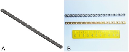
Plate-screw constructs
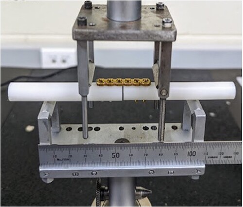
The plate construct design simulated radial osteotomy fixation with minimal fracture gap and was guided by previous studies and recommendations (Jain et al. Citation1998; Blake et al. Citation2011; Schorler et al. Citation2018). Solid polyoxymethylene rods (Acetal; Dotmar Engineering Plastics Ltd, Palmerston North, NZ) were used as a rigid bone substitute. Rods 10 mm in diameter were laser cut into 7.5-mm segments and a specifically machined guide was used to precision-drill three 1.5-mm screw holes in each segment at 90 degrees to the rod surface and at the specified hole spacing. The drill guide incorporated a 1-mm offset to create a fracture gap. Each 24-hole plate was cut into four 6-hole plates. Plate constructs were then assembled using two rods to create a 2-mm osteotomy gap stabilised with either a 6-hole, 2.0-mm, CM titanium LCP (n = 12) or a 6-hole, 2.0-mm, AM titanium LCP (n = 12) secured with 6 non-locking, 2-mm, titanium cortical screws (Arix Vet; Jeil Medical Corporation) (). Although screw torque was not formally measured, all constructs were consistently assembled by one author (SP).
Figure 2. Photograph of a plate-screw construct consisting of a 6-hole conventionally manufactured (CM) plate screwed to polyoxymethylene rods with a 2-mm osteotomy gap in the custom 4-point bending jig from an in vitro study comparing the biomechanical properties of titanium alloy additively manufactured, 3D printed and CM plate-screw constructs.
Biomechanical testing
Biomechanical testing consisted of quasi-static (single-cycle) and cyclic fatigue four-point bending tests, conducted using material testing machines for application of controlled force as well as collection of load and actuator position data. Testing design was guided by the American Society for Testing of Materials (ASTM) standard for metallic bone plate testing (ASTM Citation2017) and previous experimental studies (Bordelon et al. Citation2009; Strom et al. Citation2010). All 24 plate-constructs were loaded in a custom-designed four-point-bending jig to generate a constant bending moment over the entire plate. All samples were manually centred on the wider support rollers with the plate facing up between the narrow compression rollers. The bending moment opened up the cis gap so that the rigid rods would not interfere with plate deformation during testing. Centre span and loading span distance remained constant for all samples at 50 and 25 mm, respectively (). In this study, for both the single-cycle and fatigue testing, failure was described as plastic deformation of implants or catastrophic failure of implants (plate breakage). All plate-bone constructs were dismantled after testing to evaluate the site and extent of failure. The testing of all constructs was recorded on video for review.
Single-cycle, load-to-failure, four-point bending test
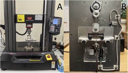
A quasi-static, monotonic, single load-to-failure test was performed on 14 constructs (7 of each type) at a rate of 0.10 mm/second under digital control of the load machine (Model 5967; Instron) with a 30-kN load cell (). Load and displacement data were recorded by the test system software (Bluehill Universal; Instron) and were plotted to create load–displacement curves using Excel 2019 version 16.76.0 (Microsoft Corporation, Redmond, WA, USA). Bending stiffness, bending structural stiffness, and bending strength were calculated as recommended by the ASTM standard (ASTM Citation2017). Bending stiffness (K; N/mm) was defined as the maximum slope of the elastic portion of the load–displacement curve, which was determined using linear regression analysis for a best fit. Bending structural stiffness (Ele; Nm2) representing the plate’s normalised effective bending stiffness independent of the apparatus configuration was calculated from the bending stiffness (K), centre span distance (a), and loading span distance (h), using the formula:
Bending strength (Nm), or yield point, was defined as the bending moment needed to produce a 0.2% offset displacement in the bone plate (ASTM method to calculate 0.2% offset displacement (q), where q = 0.002a, and a = centre span distance). The proof load (P: the applied load at the intersection of the calculated 0.2% offset on the load–displacement curve) was used with the loading span distance (h) to calculate the bending strength, using the formula:
Figure 3. Photographs of mechanical set up for single-cycle load to failure (A) and cyclic fatigue (B) testing of the biomechanical properties of titanium alloy additively manufactured, 3D printed and conventionally manufactured plate-screw constructs. In both images, a plate construct is positioned for testing in the 4-point bending test jig.
Catastrophic failure, measured as peak force and displacement, was also recorded when available.
Cyclic fatigue four-point bending test
Dynamic fatigue testing (n = 1) was initially performed under load control using a commercial material testing machine (Model 1197; Instron) with custom-made software and a 100-kN load cell. A cycle load of 0–100 N was applied at 1 Hz. The Instron model was unfortunately unable to mechanically cope at the frequency required for testing the remaining plates. Consequently, a custom electromechanical materials testing machine was built to ensure the same 10 kg cyclic loading conditions, performed under load control at 0.8 Hz (; see Supplementary Material for video). The testing machine used a slider-crank mechanism to load and unload a suspended 10 kg (0–98 N). A linear potentiometer and a limit switch were used to measure the vertical displacement at the top dead centre of each cycle. The test frequency was regulated by the speed of the direct current motor driving the crank mechanism. Fatigue testing of the remaining 9 plate-constructs (n = 5 AM and n = 4 CM) was completed with cycle and displacement data recorded by custom-designed software. The maximum load of 98 N was comparable to a worse-case scenario of approximately 100% body weight loading of the forelimb during activity for a 10-kg dog (Chao et al. Citation2013; Ichinohe et al. Citation2022). This was also correlated to the results of the single-cycle load-to-failure testing to ensure no more than 50% of the minimum mean yield load of the two plates was applied, thus remaining within the elastic region of the load–deformation curve (Malenfant and Sod Citation2014). The number of cycles until implant failure was recorded. The tests were considered as run-outs if the number of cycles reached 250,000. The number of cycles was designed to approximate the activity of a small dog confined over a 3-month post-operative period during healing of a long-bone fracture (Aper et al. Citation2003). An assumption was made that the forces and activity levels were constant throughout the testing period.
Statistical analysis
Data were analysed using InfoStat statistical program (Version 2020; Universidad Nacional de Córdoba, Córdoba, Argentina). The bending strength, bending stiffness, and bending structural stiffness under quasi-static loading and fatigue life under dynamic loading were compared between the AM and CM plate constructs. Wilcoxon (Mann–Whitney) rank sum tests were used for both testing conditions, as data were not normally distributed. Kaplan–Meier survival analysis with log rank was used to test for differences in fatigue survival probability between plates using Minitab (Version 12.3.1; Pennsylvania State University, State College, PA, USA). Statistical significance was set at p < 0.05.
Results
Single-cycle load to failure
The AM constructs had a greater bending strength (median 3.07 (min 3.0, max 3.4) Nm) compared to the CM construct (median 2.57 (min 2.5, max 2.6) Nm; p = 0.006) under 4-point bending in single cycle to failure. Similarly, the yield load was higher for the AM constructs (median 245.5 (min 240.4, max 268.2) N) than the CM constructs (median 205.2 (min 200.0, max 208.1) N; p = 0.002). The median stiffness and bending structural stiffness of the AM (69.6 (min 69.2, max 71.9) N/mm and 0.72 (min 0.67, max 0.75) Nm2, respectively) and CM constructs (65.9 (min 64.9, max 70.0) N/mm and 0.69 (min 0.68, max 0.73) Nm2, respectively) had no evidence of difference (p = 0.13). This is represented in . Load–displacement curves for all the CM and AM plate constructs tested in single-cycle load to failure are represented in .
Figure 4. Box-and-whisker plots comparing bending stiffness (A), bending structural stiffness (B), 0.2% off-set yield load (C), and bending strength (D) of titanium alloy additively manufactured (AM; n = 7) and conventionally manufactured (CM; n = 7) plate-screw constructs tested in four-point bending, single-cycle, load-to-failure in vitro. The upper and lower edges of the boxes indicate the 25th and 75th percentiles, respectively, the upper and lower whiskers indicate the 1st and 99th percentiles, respectively and the median is shown by the horizontal line inside the boxes. Different letters above each box plot indicate differences (p < 0.05) by Wilcoxon (Mann–Whitney) rank sum test.
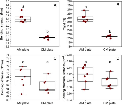
Figure 5. Load–displacement curves for conventionally manufactured (CM; dotted line; n = 7) and additively manufactured (AM; solid line; n = 7) plate-constructs tested in single-cycle load to failure in an in vitro comparison of the biomechanical properties of titanium alloy AM and CM plate-screw constructs.
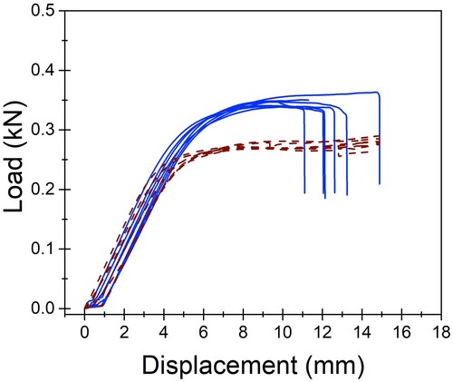
All constructs exhibited plastic deformation without any evidence of screw pull-out, screw loosening, or screw breakage. Catastrophic failure defined as plate breakage was experienced by all AM plates, indicating that the AM constructs experienced a shorter plastic deformation phase than the CM constructs. The median maximum force experienced by the AM plates before breakage was 346.85 (min 339.0, max 363.38) N. The break point of the AM plates occurred at a median displacement of 12.08 (min 10.96, max 14.88) mm. This occurred through the screw hole adjacent to the created bending stress of the osteotomy gap. At this same displacement, the CM plates had not catastrophically failed but experienced more elongation and bent beyond clinically acceptable limits. The maximum force and displacement for catastrophic failure could not be determined for the CM plates due to limitations of the jig design. However, at similar displacement to the failure point of the AM plates, the CM plates were bent approximately 45 degrees.
Cyclic fatigue testing
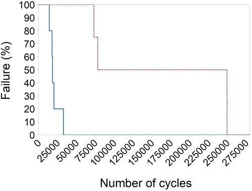
The median number of cycles to failure under 4-point bending was greater for the CM plate constructs (n = 4, median 164,272 (min 73,557, max 250,000) cycles) than the AM plate constructs (n = 5, median 18,704 (min 14,427, max 33,228) cycles; p = 0.02) (). There was evidence of difference in the survival probability between the two plate types, with the CM plates showing superior cyclic resistance compared to the AM plates (p = 0.005 according to log rank). Fifty percent of AM plates failed by 18,842 (95% CI = 14,407–33,133) cycles, while 50% CM plates failed by 78,543 (95% CI = 73,557–250,000) cycles (). Fatigue life was defined as either the number of cycles until failure or 250,000 cycles. Modes of plate failure, when it occurred, were very similar between CM and AM plates and involved breakage through the screw hole adjacent to the created bending stress of the osteotomy gap.
Figure 6. Box-and-whisker plots comparing the number of cycles before failure of conventionally manufactured (n = 4) and additively manufactured (n = 5) titanium alloy plate-screw constructs tested by cyclic fatigue in vitro. The upper and lower edges of the boxes indicate the 25th and 75th percentiles, respectively, the upper and lower whiskers indicate the 1st and 99th percentiles, respectively, and the median is shown by the horizontal line inside the boxes. Different letters indicate differences between plate types (p < 0.05) by Wilcoxon (Mann–Whitney) rank sum test.
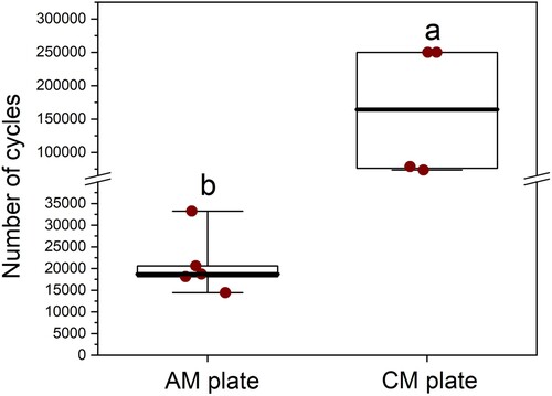
Figure 7. Kaplan–Meier survival curves for the additively manufactured (solid line; n = 5) and conventionally manufactured (dotted line; n = 4) titanium alloy plate-screw constructs tested by dynamic fatigue testing. A vertical drop in the curves indicates a plate failure event.
Discussion
Based on our results, titanium AM plates fabricated by SLM revealed no difference in bending stiffness but higher bending strength than CM plates of the same dimension when tested as plate-constructs under quasi-static 4-point bending (). The results of our 4-point bending fatigue showed that AM plate constructs had an inferior fatigue life compared to the CM constructs ( and ).
The yield load for both constructs ranged from 200 to 268 N, which corresponds to approximately two times the peak vertical force experienced by a normal 10 kg dog at a trot (Ichinohe et al. Citation2022). Appropriate confinement and exercise restriction to walking only, especially during the first few weeks after surgery, is intended to limit the peak force experienced by the implants to even lower loading, reported as 60–70% of body weight (Budsberg et al. Citation1987). Although kinetic values measured with gait analysis are only an approximation of the forces tolerated by implants during loading, our results suggest both constructs exhibit adequate strength during walking and trotting and would be appropriate for clinical applications.
While no difference in stiffness was evident between implants, the AM constructs resisted plastic deformation at a higher yield load during single cycle to failure compared to the CM constructs (median 245.5 and 205.2 N, respectively) and can therefore be interpreted as being more rigid (Filip et al. Citation2022). Strength and stiffness of a bone plate must be sufficient so that under normal weight-bearing, the implant does not undergo plastic deformation and maintains fracture stability and reduction during healing. However, implants with excessive rigidity may result in increased stress protection and osteoporosis (Larsen et al. Citation1999; Ramírez and Macías Citation2016). Toy and small breed dogs are reportedly more susceptible to complications, such as non-union, delayed union, or refracture, than medium-or large-breed dogs (De Arburn Parent et al. Citation2017). A recent experimental study assessed healing of radial osteotomies stabilised with 3D-printed titanium implants and found evidence of bone resorption parallel to the plate. This raised concerns that the AM plate was causing stress protection due to excessive rigidity (Mie et al. Citation2020).
The AM constructs in this study exhibited a shorter plastic deformation phase than the CM constructs. The shorter phase resulted in catastrophic failure once a certain displacement was reached. While the jig design prevented calculation of the maximum force and displacement for catastrophic failure of CM, there was a noticeable difference in the amount of elongation experienced by the CM construct. The AM constructs comparatively had a lower tendency to deform before failure, consistent with them being more brittle and less ductile. Lower ductility makes contouring more difficult, although this limitation can be overcome with AM by creating anatomically designed implants that do not require contouring. Embrittlement, however, can affect the fatigue life of AM products and result in poor mechanical performance under fatigue testing. This has been a concern raised by several studies (Li et al. Citation2016; Molaei et al. Citation2020; Gupta et al. Citation2021).
Our study showed that the number of cycles to failure of the AM constructs was notably less than the CM constructs. During confinement, an implant site experiences repetitive, low-impact stresses. Implants can therefore break even though yield forces are not experienced, especially during the healing period when there is a lack of bony/callus support (Aluede et al. Citation2014). Cyclic loading on an implant depends on the number of steps during activity, which depends on several factors including size, age, discomfort level, activity restriction, etc. Mean forefoot stride frequency at a walk has been previously reported as approximately 1.2–3.5 strides/second (Hottinger et al. Citation1996; Kim et al. Citation2011). If a dog is walked 3–4 times daily for up to 5 minutes, then the number of cycles in an individual limb is approximately 1,440–4,200/day. Over a 3-month healing period, 129,600–378,000 cycles could be predicted for an implant; however, 250,000 cycles were chosen for this study as an arbitrary average. Although the optimal fatigue life of implants for healing of radial bone fractures in dogs is unknown, the use of AM implants may need to be carefully selected in cases where cyclic loading is expected to be a major concern, i.e. large fracture gaps.
Additively manufactured Ti–6Al–4V parts may contain microscopic defects, such as gas entrapment and lack-of-fusion defects, because of the manufacturing technique (Gong et al. Citation2015). These defects can reduce ductility and degrade fatigue life by serving as crack initiation sites and could have contributed to the performance of the AM plates in this study. Surface roughness can also cause early crack initiation and result in reduced fatigue strength (Murr et al. Citation2009; Lee et al. Citation2022). Defects and surface quality are influenced by manufacturing processes, such as build geometry, orientation, powder size, laser density and layer thickness, and while recent work has improved optimisation of these processes, gas entrapment and surface quality remain concerns in additive manufacturing (Pegues et al. Citation2019; Molaei et al. Citation2020). The irregular temperature distribution during the additive manufacturing process also results in certain internal stresses (Molaei et al. Citation2020). Several studies have demonstrated reduced fatigue performance of AM products due to the residual stresses and internal defects (Gong et al. Citation2015; Jaber et al. Citation2022; Jiao et al. Citation2023).
Current research is therefore focused on post-process treatments to reduce residual stress and/or improve the microstructure and the defect distribution in AM Ti–6Al–4V (Molaei et al. Citation2020; Jaber et al. Citation2022). Gupta et al. (Citation2021) have shown certain heat treatments can change the microstructure of SLM-printed AM Ti–6Al–4V to a less brittle form as well as improve residual stress. This resulted in comparable characteristics to CM wrought plates, with reduced embrittlement, although potentially at the cost of reduced tensile strength. The AM plates in our study underwent stress relieving at 750°C for 2 hours in argon, however, they still failed at a considerably lower number of cycles compared to the CM plates. Few studies have looked specifically at improving the fatigue properties of SLM-printed Ti–6Al–4V plates; consequently, there is a lack of information to guide ideal manufacturing and post-treatment processes for AM plates. Lee et al. (Citation2022) have shown that fatigue performances of commercially pure, SLM-printed plates were significantly improved by surface treatments. The surface of the AM plates in this study remained visibly rough despite glass bead blasting; potentially other surface treatments might decrease brittleness.
While the outcome of AM implants used in human clinical cases is well reported, there are very few studies in the veterinary literature on their clinical use, with most consisting of a small number or case reports (Bray et al. Citation2017; Séguin et al. Citation2020; Carwardine et al. Citation2021). A systematic review found that AM implants resulted in reduced surgery time, increased accuracy, and improved outcomes in humans (Tack et al. Citation2016). Carwardine et al. (Citation2021) reported similar findings in studies of angular limb correction in dogs, with no reports of failure of the AM implants. To date there are no other studies that have biomechanically compared CM and AM plate-screw constructs. The testing protocol of this study was designed to experimentally simulate loading of a stabilised osteotomy of the radius with a small (≤2 mm) interfragmentary gap in a small dog, such as a closing wedge osteotomy. This reproduces the forces on a bone plate that occur before the bone has healed. Consequently, this model focuses on the evaluation of plate-screw constructs rather than the plate alone. A plate-screw construct is a functional combination of a bone plate with its corresponding screws and therefore represents the complete assembly that is used for fixation (Schorler et al. Citation2018). The polyoxymethylene rods were chosen according to previous validation studies (Schorler et al. Citation2018). Because of the biologic variability of bone, manufactured materials are often used as alternatives to reduce individual specimen variability and maximise repeatability. The diameter of the rods approximated that of the radius in a 10-kg dog. No failure of the synthetic bone was observed during the tests.
The loading of the constructs was applied during bending because of the significant strain and strong influence of the bending moment on long bones. Torsion and bending forces represent almost 95% of the load during walking (Gautier et al. Citation2000). The 4-point bending jig meant that the same bending moment was applied to all the screw constructs. The greatest area of strain in our model was the region that spanned the osteotomy gap. Breakage occurred at the plate hole adjacent to the osteotomy gap for both CM and AM plates. Plate holes are sites of stress concentration, so in the presence of a bony defect, plates are more likely to fail through a screw hole. The area moment of inertia is reduced at the region of a screw hole, making it more susceptible to bending forces (Hammel et al. Citation2006).
Limitations of this study are those experienced by all in vitro testing and results cannot be directly extrapolated to the clinical setting where in vivo factors are more complex in a biological setting. Sources of errors include variations in construct assembly and positioning of the construct within the material testing machines. Using a torque limited screwdriver, as reported in other studies, would have helped reduced construct variability. There were several study design limitations including the load and design features for the fatigue test. The 98–100 N load is greater than should be experienced in a normal clinical setting of confinement but provided a means of comparing implants that fail. Our model also did not consider that there is an increase in load-sharing expected over time as the bone heals. The testing machine was built to conduct the experiment in a realistic time frame and as both plate types were tested in the same manner, a valid comparison was still achieved. Bending in the caudal–cranial direction meant the plate was not on a tension surface; however, this model allowed for ease of mechanical comparison between plate types. Torsional testing of the constructs would ideally have been performed to provide additional information regarding each plate; however, we did not aim to evoke all possible construct failure modes. We did not perform fractography or assess the microstructure or surface of either the AM or CM plates to confirm differences. Lastly, we have used one machine and one method of AM manufacturing; AM implants produced by other machines/methods cannot be directly compared to our results due to previously mentioned process differences.
Our results indicate that further biomechanical testing may be necessary to ensure safety and performance of custom designed, SLM, titanium orthopaedic implants before use in clinical cases. Future research could look specifically at testing different surface and post-production treatments to improve the fatigue life of the SLM-printed AM plates. Design changes, such as increasing the size of plate by 1 mm, may be required to factor in prospective surface treatments. Scanning electron microscopy or fractography may help elucidate fatigue wear and aid in future designs.
This study provides valuable information on the use of additive manufacturing for the fabrication of orthopaedic implants and how it compares to a commercially available construct. AM titanium implants, printed to replicate a conventional titanium orthopaedic plate, were more prone to failure in a shorter fatigue period despite being stronger in single cycle to failure and we believe this needs to be investigated further before AM plates are used in place of CM plates for clinical cases in New Zealand.
Supplemental Material
Download QuickTime Video (11.1 MB)Acknowledgements
The design and technical support of the plate testing were done by the Massey University Engineering department. Statistical support was provided by Sebastian Rivera. The CAD of the AM plate was by Nathan Wilkinson (Nexus Engineering). The fabrication of the AM plate was by Warwick Downing and team (RAM3D). Funding support came from Healthy Pets New Zealand.
Disclosure statement
No potential conflict of interest was reported by the authors.
References
- Aluede E, McDonald E, Jergesen H, Penoyar T, Calvert K. Mechanical behaviour of low-cost dynamic compression plates correlates with manufacturing quality standards. International Orthopaedics 38, 141–7, 2014. https://doi.org/10.1007/s00264-013-2148-2
- Aper RL, Litsky AS, Roe SC, Johnson KA. Effect of bone diameter and eccentric loading on fatigue life of cortical screws used with interlocking nails. American Journal of Veterinary Research 64, 569–73, 2003. https://doi.org/10.2460/ajvr.2003.64.569
- *ASTM. F382-17: Standard Specification and Test Method for Metallic Bone Plates. ASTM International, West Conshohocken, PA, USA, 2017
- *ASTM. F136-13: Standard Specification for Wrought Titanium-6Aluminum-4Vanadium ELI (Extra Low Interstitial) Alloy for Surgical Implant Applications (UNS R56401). ASTM International, West Conshohocken, PA, USA, 2021a
- *ASTM. F2924-14: Standard Specification for Additive Manufacturing Titanium-6 Aluminum-4 Vanadium with Powder Bed Fusion. ASTM International, West Conshohocken, PA, USA, 2021b
- *ASTM/ISO. 52900:2021(en) Additive Manufacturing – General Principles – Fundamentals and Vocabulary. https://www.iso.org/obp/ui/#iso:std:iso-astm:52900:ed-2:v1:en (accessed 20 June 2023). International Organisation for Standardisation, Geneva, Switzerland, 2021
- Balfour RJ, Boudrieau RJ, Gores BR. T-plate fixation of distal radial closing wedge osteotomies for treatment of angular limb deformities in 18 dogs. Veterinary Surgery 29, 207–17, 2000. https://doi.org/10.1053/jvet.2000.4396
- Blake CA, Boudrieau RJ, Torrance BS, Tacvorian EK, Cabassu JB, Gaudette GR, Kowaleski MP. Single cycle to failure in bending of three standard and five locking plates and plate constructs. Veterinary and Comparative Orthopaedics and Traumatology 24, 408–17, 2011. https://doi.org/10.3415/VCOT-11-04-0061
- Bordelon J, Coker D, Payton M, Rochat M. An in vitro mechanical comparison of tibial plateau levelling osteotomy plates. Veterinary and Comparative Orthopaedics and Traumatology 22, 467–72, 2009. https://doi.org/10.3415/VCOT-08-04-0041
- Bray JP, Kersley A, Downing W, Crosse KR, Worth AJ, House AK, Yates G, Coomer AR, Brown IWM. Clinical outcomes of patient-specific porous titanium endoprostheses in dogs with tumors of the mandible, radius, or tibia: 12 cases (2013–2016). Journal of the American Veterinary Medical Association 251, 566–79, 2017. https://doi.org/10.2460/javma.251.5.566
- Brunner H, Simpson JP. Fatigue fracture of bone plates. Injury 11, 203–7, 1980. https://doi.org/10.1016/S0020-1383(80)80044-1
- Budsberg SC, Verstraete MC, Soutas-Little RW. Force plate analysis of the walking gait in healthy dogs. American Journal of Veterinary Research 48, 915–8, 1987
- Carwardine DR, Gosling MJ, Burton NJ, O'Malley FL, Parsons KJ. Three-dimensional-printed patient-specific osteotomy guides, repositioning guides and titanium plates for acute correction of antebrachial limb deformities in dogs. Veterinary and Comparative Orthopaedics and Traumatology 34, 43–52, 2021. https://doi.org/10.1055/s-0040-1709702
- Chao P, Conrad BP, Lewis DD, Horodyski M, Pozzi A. Effect of plate working length on plate stiffness and cyclic fatigue life in a cadaveric femoral fracture gap model stabilized with a 12-hole 2.4 mm locking compression plate. BMC Veterinary Research 9, 125, 2013. https://doi.org/10.1186/1746-6148-9-125
- De Arburn Parent R, Benamou J, Gatineau M, Clerfond P, Planté J. Open reduction and cranial bone plate fixation of fractures involving the distal aspect of the radius and ulna in miniature- and toy-breed dogs: 102 cases (2008–2015). Journal of the American Veterinary Medical Association 250, 1419–26, 2017. https://doi.org/10.2460/javma.250.12.1419
- De Armond CC, Lewis DD, Kim SE, Biedrzycki AH. Accuracy of virtual surgical planning and custom three-dimensionally printed osteotomy and reduction guides for acute uni- and biapical correction of antebrachial deformities in dogs. Journal of the American Veterinary Medical Association 260, 1–9, 2022. https://doi.org/10.2460/javma.21.09.0419
- Facchini L, Magalini E, Robotti P, Molinari A, Höges S, Wissenbach K. Ductility of a Ti–6Al–4V alloy produced by selective laser melting of prealloyed powders. Rapid Prototyping Journal 16, 450–9, 2010. https://doi.org/10.1108/13552541011083371
- Filip N, Radu I, Veliceasa B, Filip C, Pertea M, Clim A, Pinzariu AC, Drochioi IC, Hilitanu RL, Serban IL. Biomaterials in orthopedic devices: current issues and future perspectives. Coatings 12, 1544, 2022. https://doi.org/10.3390/coatings12101544
- Gao B, Zhao H, Peng L, Sun Z. A review of research progress in selective laser melting (SLM). Micromachines 14, 57, 2023. https://doi.org/10.3390/mi14010057
- Gautier E, Perren SM, Cordey J. Strain distribution in plated and unplated sheep tibia: an in vivo experiment. Injury 31, 37–44, 2000. https://doi.org/10.1016/S0020-1383(00)80030-3
- Gong H, Raf H, Gu H, Ram G, Starr T, Stucker B. Influence of defects on mechanical properties of Ti–6Al–4V components produced by selective laser melting and electron beam melting. Materials & Design 760, 339–45, 2015. https://doi.org/10.1016/j.matdes.2015.07.147
- Gupta SK, Shahidsha N, Bahl S, Kedaria D, Singamneni S, Yarlagadda PKDV, Suwas S, Chatterjee K. Enhanced biomechanical performance of additively manufactured Ti–6Al–4V bone plates. Journal of the Mechanical Behavior of Biomedical Materials 119, 104552, 2021. https://doi.org/10.1016/j.jmbbm.2021.104552
- Hamilton-Bennett SE, Oxley B, Behr S. Accuracy of a patient-specific 3D printed drill guide for placement of cervical transpedicular screws. Veterinary Surgery 47, 236–42, 2018. https://doi.org/10.1111/vsu.12734
- Hammel SP, Elizabeth Pluhar G, Novo RE, Bourgeault CA, Wallace LJ. Fatigue analysis of plates used for fracture stabilization in small dogs and cats. Veterinary Surgery 35, 573–8, 2006. https://doi.org/10.1111/j.1532-950X.2006.00191.x
- *Hosseini S. Fatigue of Ti-6Al-4 V. In: Hudak R, Penhaker M, Majernik J (eds). Biomedical Engineering: Technical Applications in Medicine. Pp 75–91. InTech Inc., London, UK, 2012. https://doi.org/10.5772/45753
- Hottinger HA, DeCamp CE, Olivier NB, Hauptman JG, Soutas-Little RW. Noninvasive kinematic analysis of the walk in healthy large-breed dogs. American Journal of Veterinary Research 57, 381–8, 1996
- Ichinohe T, Takahashi H, Fujita Y. Force plate analysis of ground reaction forces in relation to gait velocity of healthy Beagles. American Journal of Veterinary Research 83, 2022. https://doi.org/10.2460/ajvr.22.03.0057
- Jaber H, Kónya J, Kulcsár K, Kovács T. Effects of annealing and solution treatments on the microstructure and mechanical properties of Ti6Al4V manufactured by selective laser melting. Materials 15, 1978, 2022. https://doi.org/10.3390/ma15051978
- Jain R, Podworny N, Hearn T, Richards RR, Schemitsch EH. A biomechanical evaluation of different plates for fixation of canine radial osteotomies. The Journal of Trauma 44, 193–7, 1998. https://doi.org/10.1097/00005373-199801000-00028
- Jiao Z, Wu X, Yu H, Xu R, Wu L. High cycle fatigue behavior of a selective laser melted Ti6Al4V alloy: anisotropy, defects effect and life prediction. International Journal of Fatigue 167, 107252, 2023. https://doi.org/10.1016/j.ijfatigue.2022.107252
- Kim J, Kazmierczak KA, Breur GJ. Comparison of temporospatial and kinetic variables of walking in small and large dogs on a pressure-sensing walkway. American Journal of Veterinary Research 72, 1171–7, 2011. https://doi.org/10.2460/ajvr.72.9.1171
- Larsen LJ, Roush JK, McLoughlin RM. Bone plate fixation of distal radius and ulna fractures in small and miniature breed dogs. Journal of the American Animal Hospital Association 35, 243–50, 1999. https://doi.org/10.5326/15473317-35-3-243
- Lee S, Ahmad N, Corriveau K, Himel C, Silva DF, Shamsaei N. Bending properties of additively manufactured commercially pure titanium (CPTi) limited contact dynamic compression plate (LC-DCP) constructs: effect of surface treatment. Journal of the Mechanical Behavior of Biomedical Materials 126, 105042, 2022. https://doi.org/10.1016/j.jmbbm.2021.105042
- Li P, Warner D, Fatemi A, Phan N. Critical assessment of the fatigue performance of additively manufactured Ti–6Al–4V and perspective for future research. International Journal of Fatigue 85, 130–43, 2016. https://doi.org/10.1016/j.ijfatigue.2015.12.003
- Liu Y, Xu H, Peng B, Wang X, Li S, Wang Q, Li Z, Wang Y. Effect of heating treatment on the microstructural evolution and dynamic tensile properties of Ti–6Al–4V alloy produced by selective laser melting. Journal of Manufacturing Processes 74, 244–55, 2022. https://doi.org/10.1016/j.jmapro.2021.12.035
- Malenfant RC, Sod GA. In vitro biomechanical comparison of 3.5 string of pearl plate fixation to 3.5 locking compression plate fixation in a canine fracture gap model. Veterinary Surgery 43, 465–70, 2014. https://doi.org/10.1111/j.1532-950X.2014.12095.x
- McKenna T, Tomonto C, Duggan G, Lalor E, O'Shaughnessy S, Trimble D. Evaluation of bimodal microstructures in selective-laser-melted and heat-treated Ti–6Al–4V. Materials & Design 227, 111700, 2023. https://doi.org/10.1016/j.matdes.2023.111700
- Mie K, Ishimoto T, Okamoto M, Iimori Y, Ashida K, Yoshizaki K, Nishida H, Nakano T, Akiyoshi H. Impaired bone quality characterized by apatite orientation under stress shielding following fixing of a fracture of the radius with a 3D printed Ti–6Al–4V custom-made bone plate in dogs. PLoS ONE 15, e0237678, 2020. https://doi.org/10.1371/journal.pone.0237678
- Molaei R, Fatemi A, Sanaei N, Pegues J, Shamsaei N, Shao S, Li P, Warner DH, Phan N. Fatigue of additive manufactured Ti–6Al–4V, Part II: the relationship between microstructure, material cyclic properties, and component performance. International Journal of Fatigue 132, 105363, 2020. https://doi.org/10.1016/j.ijfatigue.2019.105363
- Murr LE, Quinones SA, Gaytan SM, Lopez MI, Rodela A, Martinez EY, Hernandez DH, Martinez E, Medina F, Wicker RB. Microstructure and mechanical behavior of Ti–6Al–4V produced by rapid-layer manufacturing, for biomedical applications. Journal of the Mechanical Behavior of Biomedical Materials 2, 20–32, 2009. https://doi.org/10.1016/j.jmbbm.2008.05.004
- Oxley B. A 3-dimensional-printed patient-specific guide system for minimally invasive plate osteosynthesis of a comminuted middiaphyseal humeral fracture in a cat. Veterinary Surgery 147, 445–53, 2018. https://doi.org/10.1111/vsu.12776
- Pegues J, Shao S, Shamsaei N, Sanaei N, Fatemi A, Warner DH, Li P, Phan N. Fatigue of additive manufactured Ti–6Al–4V, Part I: the effects of powder feedstock, manufacturing, and post process conditions on the resulting microstructure and defects. International Journal of Fatigue 132, 105358, 2019. https://doi.org/10.1016/j.ijfatigue.2019.105358
- Ramírez J, Macías C. Conventional bone plate fixation of distal radius and ulna fractures in toy breed dogs. Australian Veterinary Journal 94, 76–80, 2016. https://doi.org/10.1111/avj.12408
- Schorler H, Wendlandt R, Jürgens C, Schulz AP, Kaddick C, Capanni F. Bone plate-screw constructs for osteosynthesis – recommendations for standardized mechanical torsion and bending tests. Biomedizinische Technik. Biomedical Engineering 63, 719–27, 2018. https://doi.org/10.1515/bmt-2017-0126
- Séguin B, Pinard C, Lussier B, Williams D, Griffin L, Podell B, Mejia S, Timercan A, Petit Y, Brailovski V. Limb-sparing in dogs using patient-specific, three-dimensional-printed endoprosthesis for distal radial osteosarcoma: a pilot study. Veterinary and Comparative Oncology 18, 92–104, 2020. https://doi.org/10.1111/vco.12515
- Strom AM, Garcia TC, Jandrey K, Huber ML, Stover SM. In vitro mechanical comparison of 2.0 and 2.4 limited-contact dynamic compression plates and 2.0 dynamic compression plates of different thicknesses. Veterinary Surgery 39, 824–8, 2010. https://doi.org/10.1111/j.1532-950X.2010.00736.x
- Tack P, Victor J, Gemmel P, Annemans L. 3D-printing techniques in a medical setting: a systematic literature review. Biomedical Engineering 15, 115, 2016. https://doi.org/10.1186/s12938-016-0236-4
- Wang Q, Telha W, Wu Y, Abotaleb B, Jiang N, Zhu S. Evaluation of the properties of 3D-printed Ti alloy plates: in vivo and in vitro comparative experimental study. Journal of Clinical Medicine 12, 444, 2023. https://doi.org/10.3390/jcm12020444
- Worth AJ, Crosse KR, Kersley A. Computer-assisted surgery using 3D printed saw guides for acute correction of antebrachial angular limb deformities in dogs. Veterinary and Comparative Orthopaedics and Traumatology 32, 241–9, 2019. https://doi.org/10.1055/s-0039-1678701
- Xie P, Ouyang H, Deng Y, Yang Y, Xu J, Huang W. Comparison of conventional reconstruction plate versus direct metal laser sintering plate: an in vitro mechanical characteristics study. Journal of Orthopaedic Surgery and Research 12, 128, 2017. https://doi.org/10.1186/s13018-017-0628-6
- Yang JJ, Yu HC, Yin J, Gao M, Wang ZM, Zeng XY. Formation and control of martensite in Ti-6Al-4V alloy produced by selective laser melting. Materials and Design 108, 308–18, 2016. https://doi.org/10.1016/j.matdes.2016.06.117
- Zahn K, Frei R, Wunderle D, Linke B, Schwieger K, Guerguiev B, Pohler O, Matis U. Mechanical properties of 18 different AO bone plates and the clamp-rod internal fixation system tested on a gap model construct. Veterinary and Comparative Orthopaedics and Traumatology 21, 185–94, 2008. https://doi.org/10.1055/s-0037-1617359
- *Non-peer-reviewed