Abstract
In this paper, we study the boiling heat transfer of upward flow of R21 in a vertical mini-channel with a size of 1.6 × 6.3 mm. The heat transfer coefficient was measured as a function of heat flux for a wide range of vapor quality and for two levels of mass flow rate, G = 215 kg/m2s and G = 50 kg/m2s. The standard deviation of wall superheat over channel perimeter and in time was determined from the measurement of the wall temperature along the channel perimeter. Different heat transfer mechanisms were revealed depending on flow patterns. The main heat transfer mode for large mass flux is convective boiling. We also figure out the mode when the evaporation of thin liquid films makes the essential contribution to heat transfer. The modified models of Liu & Winterton and Balasubramanian & Kandlikar describe the experimental data well for regime when the convective boiling makes the main contribution to the heat transfer.
NOMENCLATURE
| A | = |
area of channel cross-section, m2 |
| f | = |
fanning friction factor |
| F | = |
factor of convection enhancement |
| G | = |
mass flow rate, kg/m2s |
| i | = |
specific enthalpy, J/kg |
| k | = |
thermal conductivity, W/m K |
| l | = |
heated length of the channel, m |
| M | = |
molecular mass, g/mol |
| Nconf | = |
confinement number |
| Nu | = |
Nusselt number |
| P | = |
pressure, bar |
| Pr | = |
Prandtl number |
| Q | = |
heat flux, W |
| q | = |
heat flux density, W/m2 |
| q”′ | = |
volume heat release in material, W/m3 |
| Re | = |
Reynolds number |
| Rz | = |
typical size of roughness, mkm |
| S | = |
factor of boiling suppression |
| T | = |
temperature, °C |
| T0 | = |
liquid temperature before the vapor generator, °C |
| x | = |
mass vapor quality |
| z | = |
distance from the inlet of heated channel, m |
| Greek Symbols | = | |
| α | = |
heat transfer coefficient, W/m2K related standard deviation of superheat temperature distribution, |
| Δ iLV | = |
latent heat, J/kg |
| ϵ | = |
channel wall thickness, m |
| ρ | = |
density, kg/m3 |
| σ | = |
surface tension coefficient, N/m |
| Subscripts | = | |
| CBD | = |
convective boiling dominant |
| chan | = |
channel |
| coil | = |
vapor generator |
| cL | = |
convective |
| cr | = |
critical |
| i | = |
ordinal number of a thermocouple on the channel wall |
| in | = |
inlet |
| L | = |
liquid |
| L0 | = |
entire mass flow rate is taken as liquid one |
| nb | = |
nucleation boiling |
| NBD | = |
nucleation boiling dominant |
| sat | = |
saturated |
| V | = |
vapor |
| w | = |
wall |
| τ | = |
time |
| π | = |
perimeter |
INTRODUCTION
During the evaporation and boiling of liquid in small, non-round channels, the capillary forces are significant for determining flow pattern; in turn, the features of two-phase flow are critical for heat transfer rate. Understanding these phenomena is useful in the design and optimization of compact evaporators and condensers. Compact heat exchangers are widely used in refrigeration and the cryogenic industry due to high efficiency. Usually this type of heat exchanger consists of rectangular minichannels with the gap size about 0.5–2 mm. This size becomes comparable to the capillary constant [σ /(ρL−ρV)g]1/2, and in two-phase flow, the capillary forces are significant for flow pattern and heat transfer. Many researches have been performed on boiling heat transfer in mini-channels. According to [Citation1, Citation2, Citation3, Citation4], the minichannels, unlike tubes with a large diameter, have the boiling heat transfer coefficient depend mainly on the level of heat flux and pressure; the dependency on flow rate and vapor quality is insignificant. This research proved that the nucleate boiling is the key mechanism for heat transfer, and the contribution of convective boiling is small. On the other hand, the claim that contribution of nucleate boiling in heat transfer is far from dominant [Citation5, Citation6, Citation7, Citation8, Citation9]. Lee and Lee [Citation9] demonstrated that the boiling heat transfer coefficient grows with the heat flux and vapor quality, but the effect of heat flux on boiling heat transfer coefficient is small. It was demonstrated [Citation10, Citation11] that heat transfer in minichannels depends on actual flow pattern. Experimental results [Citation12] show that the minichannel system has two mechanisms for heat transfer. This is a convective mechanism at a high vapor quality (i.e., the boiling heat transfer coefficient is dependent on vapor quality and independent of heat flux) and nucleate boiling at low vapor quality (i.e., the boiling heat transfer coefficient is independent of vapor quality and dependent on heat flux). Thus, one can see many contradictions in the available literature on this subject.
This paper deals with boiling heat transfer for upflow of R21 in a vertical rectangular minichannel. We obtained the data on local heat transfer coefficient as a function of heat flux and vapor quality at two mass flow rates, 50 and 215 kg/m2s. The relative standard deviation data on wall superheat variation in time and over the channel perimeter were obtained also. The experimental data were compared with correlation for forced boiling heat transfer developed in [Citation4] and with models from [Citation13] and [Citation14]. The pool boiling correlation in [Citation13] was replaced with the Danilova correlation [Citation15], which more accurately accounts for the boiling peculiarities of refrigerants than does the original model.
EXPERIMENTAL SETUP AND MEASURING TECHNIQUE
The experimental closed circuit is depicted in . The setup consists of several components: a pump; a cooler to keep liquid subcooled at the vapor generator inlet, flow meters, a vapor generator, an experimental section, an evaporator for the elimination pulsation of pressure, and a condenser.
Figure 1 Experimental setup.
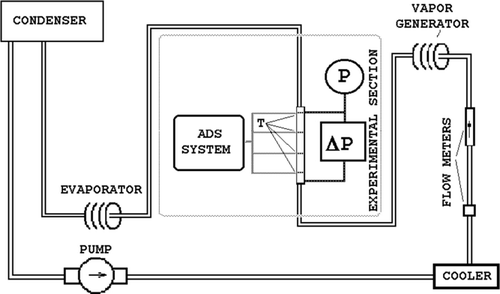
The working liquid (refrigerant 21) is pumped from the condenser via the flow meter to the vapor generator; here, a two-phase flow with desired vapor quality is prepared. Then, this flow is forwarded to the working section, flows to the evaporator, and becomes vapor-only flow. This vapor flow is fed to the condenser for complete condensation.
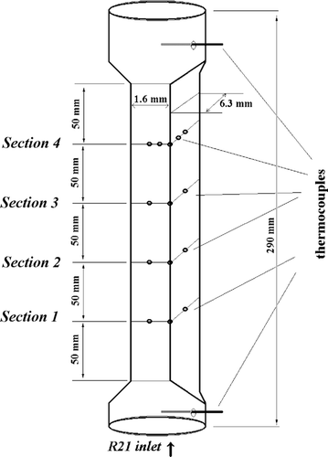
The experimental section shown in is made from a stainless steel tube with the wall thickness of 0.1 mm and length 350 mm. Every end of this tube has a flange with a power supply, pressure sensor, and thermocouple. The heated part of the tube is 290 mm. The rectangular working channel was fabricated by pressing from the round tube and its length is 250 mm. The typical size of the channel surface roughness is about 10 microns. The inner size of channel is 1.6 × 6.3 mm. The inlet and outlet of this channel has a gradual transition to a round cross-section (see ). The channel is heated by DC power. Four sections of thermocouples are arranged over the channel length on the outside. They are glued at the center of a short side, in the channel corner, and at the long side of the channel. Every thermocouple was calibrated, and the temperature measurement accuracy was 0.05. The channel and flanges have thermal insulation.
Figure 2 Test section.
The thermocouples were tested for the heating of single-phase flow and for two-phase flow without heating. All temperature data were registered through an ADC and stored in a PC; the time for single measurement was 160 ms.
The heat transfer coefficient and mass vapor quality were determined from the measured data: wall temperature distribution was measured over the channel perimeter, input saturation pressure was measured by the manometer and thermocouple (for two-phase mode), pressure drop on the experimental section was measured by a pressure gauge and input/output thermocouples (in two-phase mode), all pressure sensors and appropriate ducts were kept at 50°—(slightly above the saturation temperature for R21) to prevent liquid condensation in ducts and data distortion, the electric power supplied to the experimental section, flow rate and temperature of liquid refrigerant, electric power on the vapor generator. The temperature was determined from five time measurements (the time frame between measurements was 4 sec), and the relative standard deviation was calculated.
Experiments were carried out at the pressure from 1.5 to 2.4 bar and at two levels of flow rate: 50(± 3) and 215(± 15) kg/m2s. The heat flux density varied from 1 to 40 kW/m2. The difference between the temperature of inner and outer walls of test section defined as
The saturation temperature in the point of measuring of local heat transfer coefficient was found from the pressure calculated as a linear interpolation between the inlet and outlet pressure at the working section. The experimental data are presented as a local heat transfer coefficient averaged over perimeter that was chosen at 200 mm from the inlet (see , fourth cross-section). The accuracy for determination of heat transfer coefficient ranged from 3.5% to 35%, but for most of the data array, this accuracy was about 10% and less.
RESULTS AND ANALYSIS
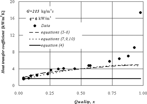
presents data on upflow boiling heat transfer coefficient as a function of vapor quality at the mass flow rate G = 215 kg/m2s. The heat flux density was kept constant at the level of q = 6 kW/m2. The vapor-liquid flow after the steam generator was fed to the channel inlet. The initial vapor quality was varied in the tests to obtain the desirable local vapor quality at the point of heat transfer coefficient measurement. With the variation of local vapor quality from zero to unity, the boiling heat transfer coefficient increases gradually. This proves to be an important role of convective heat transfer in total heat transfer rate. At the vapor quality above 0.5, the heat transfer coefficient increases with quality faster than at low quality. According to flow pattern map [Citation17], the flow pattern for G = 215 kg/m2s and vapor quality higher than 0.2 should be cell flow and annular flow with a thin liquid film on the channel wall. It supports the high heat transfer rate in rectangular minichannel without a considerable role for nucleate boiling. The probable mechanism of heat transfer especially at vapor quality higher than 0.5 is the evaporation of thin liquid films, as it was observed in [Citation9] for forced boiling in narrow gap.
Figure 3 The local heat transfer coefficient vs. quality, G = 215 kg/m2s, q = 6 kW/m2.
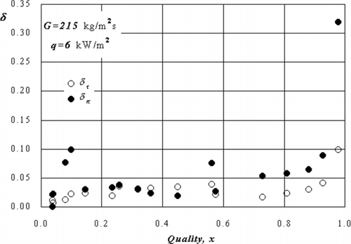
is the plotting of relative standard deviation for local wall superheat. Here, light symbols show the relative standard deviation of actual wall superheat in time during measurement session, and solid symbols are the relative standard deviation of local wall superheat over the channel perimeter. The wall temperature profile over the channel perimeter has a very low relative standard deviation and is stable in time. The temperature distribution over the perimeter is uniform except for the case of a vapor quality close to 0.1, where the transition to long Taylor bubbles occurs. While a long bubble moves on, the capillary forces in non-round channel can pull the liquid film into the channel corners, making non-uniform film thickness in the channel [Citation16]. This essential maldistribution of liquid in the channel is the reason of high data scattering for the case of x close to 0.1.
Figure 4 Relative standard deviation of temperature distribution vs. quality, G = 215 kg/m2s, q = 6 kW/m2. The dark points are on the perimeter, and empty points are in the time.
shows the heat transfer coefficient calculations by models from [Citation4], [Citation13], and [Citation14]. The calculation by the heat transfer model [Citation4] gives the formula:
The calculation of boiling heat transfer coefficient by model Liu & Winterton [Citation13] gives the equation
The calculation of boiling heat transfer coefficient by model [Citation14] gives the equation
In the authors' model [Citation14], the α L0 calculated by Petukhov correlation for ReL0 > 104 is
The friction factor f is given by
For ReL0 < 1600, the flow is considered as laminar and
In our experiment, the Dittus-Boelter correlation for αL0 gives better conformity with experimental data. Because the Reynolds number is around 1900 (at G = 215 kg/m2s), the use of Gnielinski or Dittus-Boelter correlations is not appropriate. The Dittus-Boelter correlation was used because the Gnielinski correlation gave a drop in the heat transfer coefficient relative to experimental data.
shows that modified models [Citation13] and [Citation14] have a good agreement with the experimental data at a vapor quality less than 0.5. At a vapor quality higher than 0.5, the enhancement of heat transfer was observed, which grows with the increase of vapor quality. The model [Citation4] predicts the data only for very small vapor qualities.
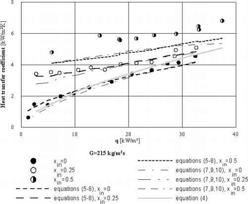
Heat transfer coefficient data vs. heat flux density at three initial qualities for the mass flux G = 215 kg/m2s are presented in . The corresponding local vapor quality range for these data is from 0.01 to 0.79. Comparison with calculations by the models [Citation4, Citation13, Citation14] is also presented. For inlet quality 0.25 and slightly subcooled liquid and for all range of used heat fluxes, the heat transfer coefficients data are in good agreement with calculation by models [Citation13] and [Citation14]. The calculation by Eq. (Equation4) describes the experimental data only for subcooled liquid at the inlet, as was in original work [Citation4]. Growth in both heat flux and quality brings an increase in the heat transfer coefficient, and the influence both of convection and nucleate boiling is essential for these considered initial qualities. For inlet quality 0.5, the experimental heat transfer coefficients exceed the calculated value for all considered models.
Figure 5 The local heat transfer coefficient vs. heat flux with constant initial quality, G = 215 kg/m2s. Points are experimental data and lines are calculations.
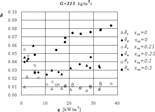
Relative standard deviation data for the wall superheat (for data from ) are plotted in . The round symbols show the data with initial vapor quality of 0.5, the diamond symbols show the data with initial vapor quality of 0.25, and triangle symbols show the data with slightly subcooled liquid at the test section entrance. The light symbols show the relative standard deviation in time, and solid symbols are relative standard deviations over the channel perimeter. A weak dependence of relative standard deviation in time is observed. It decreases when the heat flux increases. The relative standard deviation of wall superheat on the perimeter is stable on level of 3% for initial quality 0 and 0.25. Besides, for quality higher than 0.5, the relative standard deviation is essentially higher than for quality less than 0.5. It shows the considerable non-uniformity of wall superheat due to liquid flow redistribution under the action of capillary forces. The low wall temperatures correspond to thermocouples placed in a long side of the channel where the film thickness becomes very thin and film evaporation may suppress the nucleate boiling. The non-uniformity of the wall superheat over the channel perimeter exist also at low q for all inlet qualities and is the result of liquid redistribution by capillary forces in Taylor bubbles flow pattern.
Figure 6 Relative standard deviation of temperature distribution vs. heat flux, G = 215 kg/m2s. The dark points are on the perimeter, and empty points are in the time.
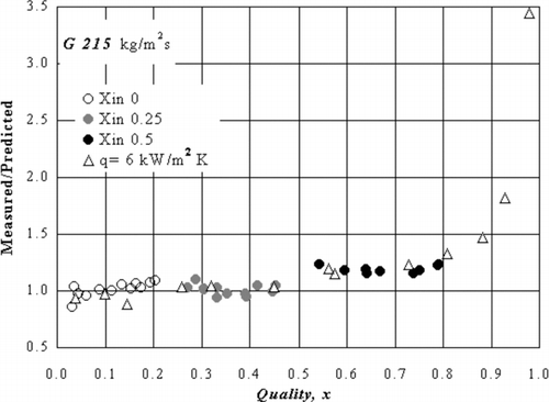
The ratio of measured heat transfer coefficient as predicted by Eqs. (Equation5, Equation6, Equation7, Equation8) versus local vapor quality is presented in . (experimental data are accumulated from and ). When the quality is below 0.5, the coincidence between experimental data and calculations by Eqs. (Equation5, Equation6, Equation7, Equation8) is good. The deviation of experimental data from calculation does not exceed the experiment accuracy. For a quality higher than 0.5, the experimental data are higher than calculations by model [Citation13], as was specified previously.
Figure 7 Experimental heat transfer coefficient divided to calculation by Eqs. (Equation5, Equation6, Equation7, Equation8), G = 215 kg/m2s.
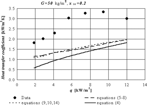
For mass flux G = 50 kg/m2s, the measured heat transfer coefficients vs. heat flux are presented in at an initial quality equal to 0.2. For a heat flux up to 10 kW/m2, the value of the heat transfer coefficient grows steadily with the heat flux. For a heat flux higher than 10 kW/m2, the heat transfer rate decreases. is the plotting of calculations by the three models [Citation4, Citation13, Citation14]. The Dittus-Boelter correlation for convection term in Eq. (Equation5) was used as in original paper [Citation13], and laminar flow correlation (14) with Nu = 5.33 was used in model [Citation14]. The measured heat transfer coefficients essentially exceed the calculation by all considered models, even at the initial quality of 0.2. The measured heat transfer coefficient grows faster than in calculations when heat flux increases. It shows the change of the mechanism of heat transfer due to capillary forces action at mass flux less then G = 50 kg/m2s.
Figure 8 The local heat transfer coefficient vs. heat flux with constant initial quality, G = 50 kg/m2s and initial quality 0.2. Points are experimental data and lines are calculations.
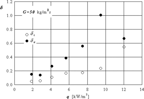
depicts the relative standard deviation of the wall superheat vs. heat flux for data presented on . Non-uniformity of wall superheat grows essentially with an increase in the heat flux density. For quality higher than 0.5 and heat flux about 12 kW/m2, the relative standard deviation over the perimeter drops, but the relative standard deviation in time increases, and these values thus became close.
Figure 9 Relative standard deviation of temperature distribution vs. heat flux, G = 50 kg/m2s and initial quality 0.2. The dark points are on the perimeter, and empty points are in the time.
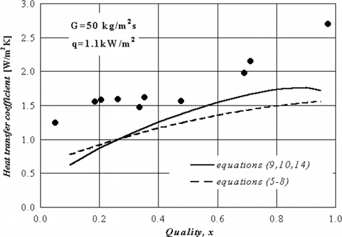
The measured heat transfer coefficient vs. quality at mass flux G = 50 kg/m2s and heat flux 1.1 kW/m2 is presented in . The heat transfer coefficient grows steadily with quality. is the plotting of calculations by models [Citation13] and [Citation14]. The Dittus-Boelter correlation for convection term in Eq. (Equation5) was used as in the original paper [Citation13], and the laminar flow correlation in Eq. (Equation14) with Nu = 5.33 was used in the Balasubramanian & Kandlikar model [Citation14]. The calculations by models [Citation13] and [Citation14] do not describe the heat transfer data well.
Figure 10 The local heat transfer coefficient vs. quality with constant heat flux, G = 50 kg/m2s. Points are experimental data, and lines are calculations.
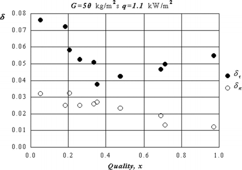
shows the relative standard deviation of the wall superheat vs. quality for data presented on . A weak dependence of relative standard deviation in time vs. quality is observed.
Figure 11 Relative standard deviation of temperature distribution vs. quality, G = 50 kg/m2s. The dark points are on the perimeter, and empty points are in the time.
CONCLUSIONS
Upflow boiling heat transfer of R-21 in a vertical rectangular channel with channel cross-section of 1.6 × 6.3 mm has been experimentally studied at two mass flow rates, 215 and 50 kg/m2s. At G = 215 kg/m2s and q = 6 kW/m2, the heat transfer degradation was not observed up to vapor quality of 0.97. For quality higher than 0.5, the measured value of heat transfer rate was considerably higher than that calculated by the Liu & Winterton [Citation13] and Balasubramanian & Kandlikar [Citation14] models.
The correlation of pool boiling heat transfer for refrigerant R-21 from Danilova [Citation15] was used in the model of Liu & Winterton, which takes into account the liquid properties as far as surface roughness. This modification allows one to account more accurate the boiling peculiarities when compared with universal boiling correlation of Cooper [Citation18] used in original paper [Citation13]. At a vapor quality less then 0.5, when heat transfer mode contributed both by convection and nucleate boiling, this modified model and Balasubramanian & Kandlikar model were in good agreement with experimental data. For high vapor quality, the liquid film becomes so thin that film evaporation impact on heat transfer became essential. At G = 215 kg/m2s and a quality higher than 0.5, this results in a heat transfer coefficient higher than that calculated by the Liu & Winterton and Balasubramanian & Kandlikar models. The measured relative standard deviation of wall superheat in time and over the channel perimeter shows the non-uniform nature of heat transfer over the channel perimeter for this quality range. The high heat transfer rate was observed for a long side of the channel.
At a low mass flow rate (G = 50 kg/m2s), the calculations by modified models of Liu & Winterton and Balasubramanian & Kandlikar do not describe the experimental data well. The measured heat transfer coefficients are considerably higher than calculated ones. It was observed also that the relative standard deviation of wall superheat over the channel perimeter was increased more than in order to compare with the data for mass flux of 215 kg/m2s. When capillary forces are redistributed, the liquid flows over the rectangular channel perimeter and heat transfer enhancement takes place.
About the Authors
 Vladimir V. Kuznetsov is the head of Department of Engineering Thermophysics and Laboratory of Multiphase System at Institute of Thermophysics Siberian Branch of Russian Academy of Sciences. He also is a professor at Novosibirsk State University, Russia. He is a graduate of Novosibirsk State University (1972) and he was awarded his Ph.D. (1978) and D.Sc. (1995) at the Institute of Thermophysics Siberian Branch of Russian Academy of Sciences. His current research interests are concerned with the study of capillarity, fluid dynamics, and heat and mass transfer in multiphase and multi-component flows, including the phase change phenomena and catalytic reactions in mini- and microchannel systems. He has published more than 140 articles covering a variety of topics. He is the deputy editor-in-chief of Journal of Engineering Thermophysics.
 Alisher S. Shamirzaev is a researcher at the Institute of Thermophysics Siberian Branch of Russian Academy of Sciences. He is a graduate of Novosibirsk State University (1993), Russia. His research interests are concerned with the study of capillarity, fluid dynamics, and heat and mass transfer in multiphase flows, including the phase change phenomena in mini- and microchannel systems. He has published more than 20 articles in journals and conference proceedings.
Related Research Data
REFERENCES
- Lazarek , G. M. and Blake , S. H. 1982 . Evaporative Heat Transfer, Pressure Drop and Critical Heat Flux in Small Vertical Tube with R-113 . International Journal Heat and Mass Transfer , vol. 25 ( 7 ) : 945 – 960 .
- Wambsganss , M. W. , France , D. M. , Jendrzejczyk , J. A. and Train , T. N. 1993 . Boiling Heat Transfer in a Horizontal Small-Diameter Tube . Journal of Heat Transfer , vol. 115 : 963 – 972 .
- Train , T. N. , Wambsganss , M. W. and France , D. M. 1996 . Small Circular and a Rectangular Channel Boiling with Two Refrigerants . International Journal Multiphase Flow , vol. 22 : 485 – 498 .
- Tran , T. N. , Wambsganss , M. W. , Chyu , M. C. and France , D. M. A Correlation for Nucleate Flow Boiling in a Small Channel . Proc. Int. Conf. On Compact Heat Exchangers for Process Industries . pp. 291 – 304 .
- Robertson , J. M. 1979 . Boiling Heat Transfer with Liquid Nitrogen in Braised-Aluminum Plate-Fin Heat Exchangers , AIChE Symposium Series 75 vol. 189 , 151 – 164 .
- Robertson , J. M. and Lovergrove , P. C. 1983 . Boiling Heat Transfer with Freon 11 in Brazed Aluminum Plate-Fin Heat Exchangers . Journal of Heat Transfer , vol. 105 ( 33 ) : 605 – 610 .
- Robertson , J. M. The Correlation of Boiling Coefficients in Plate-Fin Heat Exchanger Passages with a Film Flow Model . 7th Int. Heat Transfer Conference Munich . pp. 341 – 345 .
- Wadekar , V. V. 1992 . Flow Boiling of Heptane in a Plate-Fin Heat Exchanger Passage, Compact Heat Exchangers for the Process and Power Industries . ASME HTD , vol. 201 : 1 – 6 .
- Lee , H. J. and Lee , S. Y. 2001 . Heat Transfer Correlation for Boiling Flows in Small Rectangular Horizontal Channels with Low Aspect Ratios . Int. J. of Multiphase Flow , vol. 27 : 2043 – 2062 .
- Kuznetsov , V. V. and Shamirzaev , A. S. Two-Phase Flow Pattern and Boiling Heat Transfer in Non-Circular Channel with a Small Gap . Proc. Two-Phase Flow Modeling and Experimentation . Pisa, Italy. vol. 1 , pp. 249 – 253 .
- Kew , P. A. and Cornwell , K. 1997 . Correlation for the Prediction of Boiling Heat Transfer in Small Diameter Channels . Applied Thermal Engineering , vol. 17 ( 8–10 ) : 705 – 715 .
- Feldman , A. , Marvillet , C. and Lebouche , M. 2000 . Nucleate and Convective Boiling in Plate Fin Heat Exchangers . Int. J. of Heat and Mass Transfer , vol. 43 : 3433 – 3442 .
- Liu , Z. and Winterton , R. H. S. 1991 . A General Correlation for Saturated and Subcooled Flow Boiling in Tubes and Annuli, Based on a Nucleate Pool Boiling Equation . Int. J. of Heat and Mass Transfer , vol. 34 : 2759 – 2766 .
- Balasubramanian , P. and Kandlikar , S. G. 2004 . An Extension of the Flow Boiling Correlation to Transition, Laminar and Deep Laminar Flows in Minichannels and Microchannels . Heat Transfer Engineering , vol. 25 ( 3 ) : 86 – 93 .
- Danilova , G. N. 1970 . Correlation of Boiling Heat Transfer Data for Freons . Heat Transfer—Soviet Research , vol. 2 ( 2 ) : 73 – 78 .
- Kuznetsov , V. V. , Safonov , S. A. , Sunder , S. and Vitovsky , O. V. Capillary Controlled Two-Phase Flow in Rectangular Channel . Proc. Int. Conf. on Compact Heat Exchangers for Process Industries . pp. 291 – 304 .
- Kuznetsov , V. V. , Dimov , S. V. , Shamirzaev , A. S. , Houghton , P. A. and Sunder , S. Upflow Boiling and Condensation in Rectangular Minichannels . First International Conference on Microchannels and Minichannels . Rochester, New York. Edited by: Kandlikar , S. G. pp. 683 – 689 .
- Cooper , M. G. 1984 . Saturation Nucleation Pool Boiling—A Simple Correlation . IChemE Symp. Series , vol. 84 : 785 – 793 .
- Danilova , G. N. and Kupriyanova , A. V. 1970 . Boiling Heat Transfer to Freons C318 and 21 . Heat Transfer—Soviet Research , vol. 2 : 79 – 83 .
- Gogonin , I. I. 1970 . Heat Transfer of Boiling Refrigerant 21 at Natural Convection Condition . Kholodil'naya Tekhika , vol. 3 : 24 – 28 .
- Nishikawa , K. , Fujita , Y. , Ohta , H. and Hidaka , S. 1979 . Heat Transfer in Nucleate Boiling of Freon . Heat Transfer—Japanese Research , vol. 8 ( 3 ) : 16 – 36 .