
 ?Mathematical formulae have been encoded as MathML and are displayed in this HTML version using MathJax in order to improve their display. Uncheck the box to turn MathJax off. This feature requires Javascript. Click on a formula to zoom.
Abstract
As a new type of fin structure in finned tube heat exchangers, dimple turbulators exhibit excellent potential for thermo-hydraulic performance enhancement. A three-dimensional numerical simulation study was conducted to investigate the influences of five kinds of innovative concave dimple turbulators (CDTs), namely – elliptical dimple, conical frustum dimple, trapezoidal prism dimple, leeward triangular dimple and upward triangular dimple (UwTD) on the thermo-hydraulic performance enhancement in a plate fin-and-elliptical tube (PFET) heat exchanger, where CDTs are textured on the fin surface transversely between the elliptical tubes. The computational results are analyzed by considering the performance evaluation criterion for the PFET heat exchangers with different types of CDT shapes. The present investigation demonstrates that the heat transfer enhancement is intimately pertained to ejection with longitudinal counter-rotating flow, strengthened secondary flow and vortex structures at the downstream rim of CDT. A parametric study on the CDTs indicated that the UwTD vortex turbulators give better thermo-hydraulic performance under the present conditions. The numerical simulation results illustrated different secondary flow structures and heat transfer characteristics of the CDTs with various shapes, which disclosed the influential mechanisms of differently shaped dimple turbulators on the heat transfer augmentation in PFET heat exchangers.
Introduction
A major challenge for the twenty first century is the energy crisis. There is a need for energy conservation by using advanced high-tech equipment and application of more efficient technologies [Citation1]. Enhancing the energy efficiency in thermal industries is an engineering challenge which continues to attract a lot of research attention.
The demands of the thermal industries for advanced compact heat exchanger devices having high thermo-hydraulic performance are increasing due to their need in applications such as combined cooling, heating, and power systems, petrochemical/nuclear plants, heating, ventilation, air-conditioning & refrigeration (HVAC&R) systems, aviation and automobile industry, etc. This has led to various designs of fin-and-tube heat exchangers (FTHEs) [Citation2]. FTHEs with elliptical tubes are utilized in compact thermal recovery equipment with the purpose to save energy in thermal engineering applications.
Thus far, a series of extensive studies have been done to examine the aerodynamic-thermohydraulic performance of elliptical shaped tubes. The experimental/numerical results illustrated that the elliptical tube shows better combined thermo-hydraulic characteristics compared to a circular tube due to the slender shape and streamlined surface of the elliptical tube which has a minuscule frontal area, and thus has a good synergism parameter [Citation2]. For this reason already, finned elliptical tube heat exchangers are frequently adopted in HVAC&R systems instead of finned circular tube heat exchangers, to reduce the pressure drop and consequently a lower pumping cost is achieved [Citation3,Citation4]. Additionally, elliptical tubes are able to enhance the compactness of FTHEs, in such a way that more tubes can fit into a specified volume. The airflow field around an elliptical tube consists of a horseshoe vortex (corner vortex) in the stagnation region, a von Kármán vortex street in the middle and a dead air zone at the junction of the elliptical tube and the plate fin surface [Citation5].
The thermo-hydraulic performance of a FTHE often is enhanced by modification of the heat transfer fin surface patterns in the streamwise direction. According to the information available in the field of enhancing the heat transfer of FTHEs [Citation6,Citation7], the thermal performance in fluid flow channels may be augmented essentially by means of flow manipulators such as vortex generators [Citation8–12], porous solids [Citation13,Citation14], as well as by use of turbulators, also called artificial roughnesses, such as dimples [Citation15,Citation16], grooves [Citation17,Citation18] or ribs [Citation19,Citation20]. These perturbations affect the airflow and provide three-dimensional fluid mixing and also generate transverse/longitudinal counter-rotating vortices.
Heat transfer augmentation using these techniques inevitably leads to a considerable increase of the hydrodynamic resistance that adversely affects the pumping cost due to the increase in frictional losses. Several researchers have strived to design a turbulated channel which can enhance the heat transfer with minimum pumping losses by adopting numerical and experimental methods. Most of the experiments are also carried out to understand the effects of the geometrical parameters of the roughness on flow and heat transfer characteristics and turbulent statistics in the flows through the duct of a turbulated surface.
Turbulators are employed in an extensive variety of heat-exchanging applications, e.g. compact heat exchangers [Citation21,Citation22], gas turbine blade cooling devices [Citation23,Citation24], solar air heaters [Citation25,Citation26], and cooling device for electronic components [Citation27,Citation28]. One of the first published investigations of turbulators for heat transfer enhancement seems to be that of Webb [Citation2]. In a pioneering study, Firth and Meyer [Citation29] carried out a computational investigation of the heat transfer and friction factor performance of four different types of turbulated surfaces in a gas-cooled reactor. Sharma and Kalamkar [Citation30] provide a general overview of the recent research and development of several turbulated surfaces for enhancement of thermo-hydraulic performance in the heat transfer devices.
It has been specified that the turbulators used on the heat-transferring surface interrupt the laminar (viscous) sublayer, which decreases the thermal resistance and promotes turbulence in a region near to the artificially roughened surface and hence provides better heat transfer. The turbulated surfaces have a larger heat transfer coefficient than smooth surface walls due to further turbulence close to the wall and an increase in heat transfer area due to the roughness. An efficient heat transfer augmentation technique is required to not only improve the heat transfer significantly, but also minimize the airflow resistance as much as possible.
During the last years, the innovation of utilizing a dimpled surface instead of protruding turbulators has acquired great attention as dimples provide high heat transfer augmentation and a lower pressure loss penalty. To support this notion, in a valuable survey, Ligrani et al. [Citation31] gathered data from a huge range of resources and compared them by employing the performance evaluation criterion. Accordingly, the dimple configurations are, unlike rib turbulated surfaces, indicated to give high heat transfer enhancement at a relatively low pressure loss increase, as shown in . Essentially the physics and patterns of the airflow inside the concave dimple are complicated and it is still not entirely understood. But considering the properties of the concave dimple structure, the release of multiple longitudinal vortex pairs caused by the spherical dimple cavity is a three-dimensional structure (see ) [Citation15,Citation16].
Figure 1. Comparison of thermal-hydraulic performance parameters of various heat transfer enhancement techniques by use of turbulators with selected data from Ligrani et al. [Citation31].
![Figure 1. Comparison of thermal-hydraulic performance parameters of various heat transfer enhancement techniques by use of turbulators with selected data from Ligrani et al. [Citation31].](/cms/asset/2506ee71-60c6-471f-9def-7a004d50b35d/uhte_a_1611132_f0001_c.jpg)
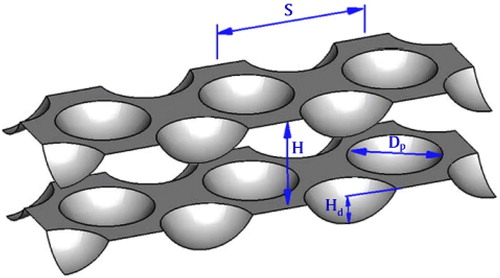
Figure 2. A conceptual perspective of ED induced flow phenomena.
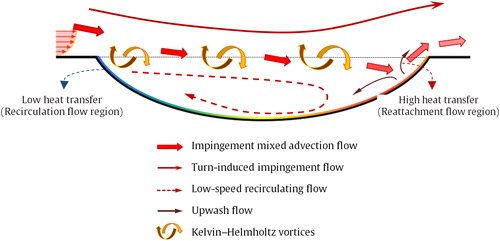
According to these investigation results, predominantly three interesting flow types influence heat transfer processes over the concave dimple turbulator (CDT) surface: (i) separation/reattachment flow, (ii) downward/upwash flow in the boundary flow and (iii) secondary flow vortex shedding (i.e. Kelvin–Helmholtz vortices and mostly counter-rotating streamwise vortices in the shear layer); in order to make headway for the turbulent mixing between the mainstream airflow and the flow inside the CDT. Actually, the edge and central vortex pairs, which are periodically shed from each concave dimple, to be more precise, the ensuing effects of the separating shear layer on the reattachment flow structure, induced local instabilities and re-initialization of the boundary layer causes significant increases in the local heat transfer coefficients. Furthermore, as a mature technology dimples are manufacturable and affordable compared to other artificial roughness. That is another reason why dimples are a more attractive proposition. Nevertheless, recent technology in the additive manufacturing arena, for instance Direct Metal Laser Sintering or 3 D Metal Printing, offers innumerable possibilities for the progress of advanced FTHEs with innovative dimple turbulators.
The first pervasive research related to dimple concavities was performed by Snedeker and Donaldson [Citation32] investigating the flow structures on a dimpled surface. Terekhov et al. [Citation33,Citation34] experimentally examined the flow structures in a single dimpled surface by tracking hydrogen bubbles, using laser Doppler anemometry method and soot-oil visualization technique. The results of these investigations determined many characters of the oscillation behavior of the vortex in a dimpled surface. Afanasyev et al. [Citation35] carried out an experimental investigation on the overall heat transfer and pressure drop for turbulent flow over a flat surface with staggered array of spherical dimples. According to their research, substantial increases (about 40%) in heat transfer without appreciable pressure losses were reported.
The performance of roughened solar air heaters with various types of artificial roughness geometries has been studied by a number of researchers [Citation36,Citation37]. According to these research works, the thermo-hydraulic performance of dimpled surfaces was superior to that of a surface with continuous ribs. Thus the heat transfer enhancement with dimple concavities can be achieved with a relatively low pressure drop penalty. Bi et al. [Citation38] studied the local heat transfer characteristics in mini-channels with enhanced dimples and cylindrical grooves by using PEC (performance evaluation criteria) and field synergy principle techniques. They reported that the dimpled surface presented the higher performance of the heat transfer enhancement than the cylindrical grooved surface. Xie et al. [Citation39] compared thermo-hydraulic performance of a blade tip-wall with pins, dimples and protrusions. They observed that the dimples had best overall performance for the internal blade tip cooling. Hwang et al. [Citation40,Citation41] carried out a study on the heat transfer and thermal performance on periodically dimple-protrusion patterned walls. Ligrani et al. [Citation42–44] experimentally determined the flow structure using flow-visualization images and surveys of time-averaged characteristics of the vortex structures in a channel with dimples and protrusion on opposite walls. Among other results, they showed that a main vortex pair was shed periodically from the center of each dimple, and also two additional secondary vortex pairs were constituted close to the spanwise edges of each dimple. Park and Ligrani [Citation45] employed numerical simulations to investigate the heat transfer characteristics and flow structure for seven different dimpled surfaces in a channel. Elyyan et al. [Citation21] performed direct numerical simulations and large eddy simulations in a finned bank with dimples and protrusions in a compact heat exchanger. They proved that enhancement of heat transfer on the dimpled surface was brought about by vortices impinging in the reattachment area of the cavity. Additionally, they found that the vorticity created within the dimple cavity and at the dimple edge contributed significantly to heat transfer enhancement on the dimple side. Lienhart et al. [Citation46] employed experimental and direct numerical simulation investigation of the turbulent flow over dimpled surfaces. This study implied that it is feasible to obtain the heat transfer augmentation by shallow dimples without significant additional pressure losses typically encountered with deep dimples. Chyu et al. [Citation47] experimentally examined the enhancement of surface heat transfer in a channel using two different dimple shapes. They reported that the dimpled surface provided about 2.5 times higher heat transfer rate than that of the smooth surface, and the pressure losses were about half of that created by rib turbulators.
The achievements published in the literature point out those concave formed dimples in comparison to other conventional heat transfer enhancement techniques show the best thermo-hydraulic performance which is outlined as the ratio between the heat exchange and flow resistance. In case of utilizing concave dimples as artificial roughness the thermo-hydraulic performance becomes optimal in comparison with other heat transfer augmentation techniques like grooves and ribs.
In previous years numerous investigations have been done focusing on the influences of dimple geometric parameters on the flow and heat transfer characteristics in a channel. Isaev et al. [Citation48–50] carried out a series of investigations for predicting the detailed tornado-like vortex-jet structures on the dimpled surface with various dimple geometries and Reynolds numbers. The influence of dimple depth and channel height on the heat transfer and pressure drop characteristics in the turbulent regime was studied by Moon et al. [Citation51]. Also, they found that heat transfer and friction factor augmentation increased with reducing the channel height and increasing the dimple depth. Flow structure characteristics above the dimpled surface with different dimple depths in a rectangular channel were experimentally examined by Won et al. [Citation52]. Chen et al. [Citation53] employed numerical simulations to investigate the heat transfer performance in turbulent channel flow over a dimpled surface. They carried out investigations with configurations of both symmetric and asymmetric dimples with different depth ratios. As a result, they found that the optimum dimple configuration for enhancing heat transfer was obtained for the case of an asymmetric dimple with a depth ratio of According to their research, the configuration of the asymmetric dimple achieved a more competitive heat-exchange surface than the symmetric dimple having the same depth ratio and circular shape print diameter. An experimental and numerical study on the heat transfer enhancement mechanism of turbulent flow over a staggered array of dimples in a narrow channel was presented by Turnow et al. [Citation54]. They showed that the maximum hydraulic and thermal performances are obtained for a ratio of the depth of the dimple to the diameter of 0.26 while the heat transfer rate was enhanced up to 201% compared to a smooth channel. Tay et al. [Citation55] experimentally determined the flow structure above the dimpled surface by visualization in a recirculating water tunnel with depth to diameter ratios ranging from 5% to 50% by utilizing a dye-injection technique. Rao et al. [Citation56] experimentally and numerically explored the heat transfer and turbulent flow characteristics over surfaces with arrays of spherical and teardrop dimples. They reported that the total heat transfer enhancement of the channels with spherical dimples and teardrop dimples can be, respectively, 1.64–1.85 and 2.0–2.2 times the fully developed smooth channel flow. Kim et al. [Citation57] generated a Pareto-optimal front solution in staggered elliptic dimpled channels, employed a hybrid evolutionary multi-objective optimization algorithm with the Kriging method.
According to the foregoing literature survey, it is found that most previous investigations merely focused on the heat transfer and pressure drop characteristics in a straight channel (e.g. solar air heater) having conventional dimpled surface structures such as hemispherical dimples, while only a few papers have been published to investigate the thermo-hydraulic performance in a finned tube heat exchanger with concave dimples. In addition, there are no research studies of new distinct types of CDTs enhancement for plate fin-and-elliptical tube (PFET) heat exchangers.
The main objective and purpose of the present research work is to introduce five new and different types of CDTs, namely – elliptical dimple (ED), conical frustum dimple (CFD), trapezoidal prism dimple (TPD), leeward triangular dimple (LwTD) and upward triangular dimple (UwTD) for application in a PFET heat exchanger. A three-dimensional computational fluid dynamics numerical investigation is carried out to explore the effects of the geometric shape of the CDTs on the heat transfer and fluid flow characteristics and also the performance evaluation criterion in the PFET channels. Consequently, new and more details of the flow physics structure, which is formed within and above CDTs, are offered to give more insight into the mechanisms resulting in surface heat transfer augmentations.
Description of 3D physical and mathematical model
Physical model and geometrical features of dimples
A three-dimensional schematic isometric view of the core region of a PFET heat exchanger with a staggered array of new and distinct type of CDTs is depicted in .
Figure 3. Isometric view of core region of a plate finned elliptical tube bank with textured CDTs.
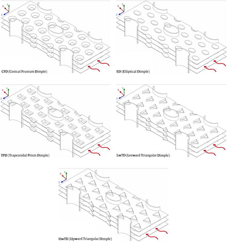
In the present investigation, five kinds of innovative CDTs are adopted, namely – (1) ED, (2) CFD, (3) TPD, (4) LwTD, and (5) UwTD.
In order to assess the advantages of dimpled surfaces of FTHE, the present three-dimensional numerical study investigates elliptical tubes having a semi-major diameter and a semi-minor diameter
The tube ellipticity ratio e is expressed by the formula
The fin material is aluminum and two neighboring plate fins form a channel with a fin pitch
mm and plate fin thickness
mm. The longitudinal tube pitch is
mm and the transverse tube pitch is
mm.
The channel geometric characteristics and coordinates of a PFET heat exchanger, which consists of dimples and protrusions on opposite surfaces, are shown in . It has three-rows of elliptical tubes in a staggered arrangement. The location of the center of the CDT base is determined by (dimple streamwise pitch),
(dimple spanwise pitch) as depicted in .
Figure 4. Schematic representation of a transverse section and plane view of the dimple finned elliptical tube heat exchanger and boundary conditions for the computational domain.
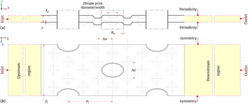
Details of the CDT parameters are listed in . As the figures in indicates, is the print diameter of the globular dimple shape (namely – conical frustum and elliptical),
represents the width of a non-globular dimple (namely – trapezoidal prism and leeward/upward triangular),
and
represent the diameter at the bottom of the conical frustum and the width at the bottom of the TPD, respectively.
Table 1. Geometric characteristics of individual dimple patterns.
The print diameter (width
) of the concave dimple with a sharp edge was kept constant at 5 mm, whereas the dimple depth
was set to
However, the plate fin-dimple channels with shallower dimples
show relatively lower pressure loss than the profound dimples [Citation54]. As regards to concave dimples with a depth to print diameter ratio of
a considerable augmentation of heat transfer is documented [Citation55]. For the conical frustum and the TPD, the ratio between the diameter (width) at the bottom and the diameter (width) at the top of the conical frustum (trapezoidal prism) is set as 0.60.
The LwTD/UwTD shape is an equilateral triangle. The bottom face of the LwTD and UwTD is slanted and filled toward the top of the fin surface. In a way the slanting of the LwTD and UwTD is toward the upstream apex and downstream side edge of dimple, respectively. Each LwTD/UwTD has a pair of opposed diverging sidewalls, which are also of triangular form. In fact, as presented in , each of the pair of sidewalls is basically perpendicular to the fin surface of the PFET heat exchanger. Side walls merge at the apex of the triangular dimple at a height which also could be perpendicular to fin surface. As mentioned, the UwTD is an equilateral triangle where the base of the bottom wall merges smoothly with the fin surface. During the passage of airflow on the upward triangular dimpled surfaces, diverging vortices exist along the innermost edges of the upper margins of the side walls, and also a pair of counter-rotating streamwise vortices is produced. These counter-rotating vortices not only delay the airflow separation but also enhance the mixing and disturbance effects of the downstream airflow, particularly, the airflow between the elliptical tubes. Indeed, two counter-rotating vortices are created along the vertical side edges to energize the boundary layer flow [Citation58].
demonstrates a schematic of the assigned boundary conditions and three-dimensional computational domain for the computations of the flow and heat transfer in the channel with built-in elliptical tubes and various types of CDTs, in which the three spatial directions x, y, z are streamwise, normal, and spanwise coordinates, respectively. Two longitudinally extended channels with lengths of 10 and 40 times the fin spacing, are connected to the upstream and downstream of the actual central portion of the computational domain, respectively. These are furthermore designed to minimize and avoid influences of flow disturbance and recirculation from the computational domain outlet. The actual central portion acts as the principal analysis domain. The central domain was embodied as a real three-dimensional model of a finned tube heat exchanger with three rows of elliptical tubes.
Flow governing equations and turbulence modeling
For the current investigation, steady three-dimensional incompressible dry airflow is conjectured to be Newtonian with constant thermophysical properties and without viscous dissipation. The usage of constant thermophysical properties is justified by very small temperature fluctuations all over the airflow. The three-dimensional computational fluid dynamics simulations of the thermo-hydraulic characteristics in the PFET heat exchanger with innovative CDTs are carried out by a linear eddy-viscosity turbulence model. The three-dimensional RANS (Reynolds-averaged Navier–Stokes) codes are able to cover most of the complex secondary flow phenomena, e.g. formation of vortices, boundary layer separation, and unsteady effects.
Using the vector operator notation, the governing equations utilized to reveal the steady fluid flow and heat transfer involve (i) mass conservation (continuity equation), (ii) momentum conservation (RANS equation) and (iii) energy conservation (energy equation). They can be compactly written in vectorial notation as follows:
Continuity equation:
(1)
(1)
RANS equation:
(2)
(2)
where ρ is the fluid density, U is the fluid velocity vector,
is the density-normalized pressure perturbation and
is the effective viscosity given by
Reynolds-averaged energy equation:
(3)
(3)
This study aims to examine the three-dimensional turbulent airflow generated by CDTs. The SST (Shear Stress Transport) turbulence model, developed by Menter and coworkers [Citation59,Citation60] which merges the near-wall κ-ω model with a low-Reynolds number κ-ε model for the boundary layer outer-region, is applied in the numerical simulations to calculate the turbulent flow. It is an improved version of the Menter’s turbulence model with the extra ability to account for the transport of the main turbulent shear stress in pressure gradient boundary-layers.
The SST turbulence model accounts for the transport of the turbulent shear stress and enables highly accurate predictions of the onset of turbulence and amount of air flow separation. Furthermore, the functionality of the SST
turbulence model is more precise, dependable and extremely computationally-efficient for various patterns of complex flow geometries compared with other linear eddy-viscosity turbulence models [Citation61].
In the SST turbulence model, the transport equations for the turbulent kinetic energy κ, and the specific energy dissipation rate ω, are defined as below [Citation59]:
(4)
(4)
(5)
(5)
In the above equations, the terms and
are the generation of κ and ω, respectively;
and
denote the dissipation of κ and ω, respectively and
is the cross-diffusion term, resulting from the transformation between the
and the
models. The terms
and
are turbulent Prandtl numbers for κ and ω, respectively, depending on the degree of blending. The detailed descriptions of the blending functions and closure coefficients appearing in the above equations can be found in Refs. [Citation59,Citation62].
It is generally accepted that the integration of the boundary layer through the thin viscous sub-layer near the wall is done by using wall function boundary conditions. The challenge is, however, that a rigorous low-Reynolds number model needs a very fine grid resolution. This requirement can hardly be attained for all walls in complex geometries. The SST turbulence model has the advantage that an analytical expression is known for ω in the viscous sub-layer region, which can be applied to attain the mentioned purpose. The principal idea is to blend the wall value of ω between the logarithmic and the low-Re formulations. This new wall boundary condition has been implemented in combination with the SST
turbulence model. According to Menter’s SST
the exact solution of ω in the viscous sub-layer is [Citation59]:
(6)
(6)
where y is the distance to the wall,
is a constant of the model equal to 0.075 and
Thus at the wall where
ω goes to infinity. The more detailed descriptions of the above subject which are out of the scope of this study can be found in Refs. [Citation59,Citation60] and will not be restated here.
Boundary-flow conditions and numerical scheme
As seen in , a combination of the inlet, outlet, walls, symmetry and periodic boundary conditions was applied in the three-dimensional computational domain with the intention to demonstrate the physical and geometric attributes of the flow with heat transfer through CDT arrays.
At the upstream region boundary, dry airflow is entering the computational domain and is assumed to have a uniform velocity () and a uniform temperature of
K. The inlet turbulence intensity level is set to 3%. The air properties are assumed to be constant and evaluated at
At the end of the downstream region, the streamwise gradient for all variables is set to zero. In the present numerical simulations, a constant elliptical tube wall surface temperature of 293 K was imposed in the three-rows of elliptical tubes. At all the solid surfaces (elliptical tube wall and fin surface), a no-slip condition for the velocity is considered. Periodic boundary condition is established for the computational domain boundaries parallel to the fin surface in the streamwise coordinate x. A symmetric boundary condition is exerted to the boundaries on each side of the subdomain in the normal coordinate y, i.e. normal gradients are equal to zero. Moreover, the coupling boundary condition
and
was prescribed at the solid–fluid interface.
The aforementioned governing equations and the boundary conditions of the PFET heat exchanger are solved by the commercial computational fluid dynamics software package ANSYS CFX® 16.0 (ANSYS, Inc.) [Citation62] based on the finite-volume method for the thermo-fluid dynamics analysis. This code solves the RANS equations with a high-resolution scheme for the advection terms as well as turbulence numeric. The high-resolution scheme is a bounded second order upwind biased discretization. The fully coupled momentum and energy equations are solved simultaneously. The maximum normalized residual values of all discretized equations are maintained at less than 10−8 as the criterion of convergence of the solutions.
Computational simulation methodology
Appraisals parameters
The principal aim of the present investigation is to predict and simulate the characteristics of heat transfer and turbulent flow in a PFET heat exchanger with five new types of CDTs. The appraisals parameters used in the study are now described.
For the airflow the Reynolds number is important:
(7)
(7)
The Reynolds number is defined based on the hydraulic equivalent diameter
and on the maximum air velocity
corresponding to the minimum air free flow cross-sectional area
which is determined as:
(8)
(8)
(9)
(9)
where V denotes the volume of the computational domain and At indicates the total heat-transfer surface area and σ is the contraction coefficient.
The overall average heat transfer coefficient of the air-side plate fin tube surface is defined as:
(10)
(10)
Here is the heat capacity flow rate, Tin is the bulk inlet temperature taken as constant. The definition of the bulk temperature at the outlet Tout and the logarithmic mean temperature difference ΔTlm are given by the equations:
(11)
(11)
(12)
(12)
In EquationEq. (11)(11)
(11) , ux represents the velocity in the streamwise direction perpendicular to the outlet cross-section Aout. The overall air-side surface effectiveness
is calculated from the fin efficiency
using the approximation method proposed by Schmidt [Citation63]. Because the fin efficiency is dependent on the air-side heat transfer coefficient, an iterative calculation is needed. The local heat transfer coefficient,
is calculated from:
(13)
(13)
where
is the span-averaged local heat flux, Tairflow,x is the mass-weighted average air temperature of the cross-section and Tfin,x is the span-averaged local fin temperature.
The thermal performance of PFET heat exchangers is evaluated in terms of the Nusselt number. Hence, the streamwise local Nusselt number is defined as:
(14)
(14)
where
is the bulk mean temperature, and is expressed as:
(15)
(15)
The average Nusselt number Nu can be obtained by:
(16)
(16)
The average pressure drop in the flow of the FTHE can be expressed in terms of the dimensionless friction factor f described as proposed by Kays and London [Citation64]:
(17)
(17)
The air-side heat transfer performance of the dimpled PFET heat exchanger is provided in terms of the dimensionless Colburn j factor as follows:
(18)
(18)
As is known, secondary flow plays a significant role for the heat transfer intensification in FTHEs with flow manipulators/turbulators. The secondary flow is the flow on cross-sections normal to the main flow. This direction is aligned with the direction of heat transfer in fluid flow because moving fluid transports heat along the main flow direction.
Therefore, the ratio of inertial force induced by the secondary flow to viscous force is defined as the dimensionless secondary flow intensity number [Citation65]. The local average intensity of the secondary flow in a small volume is defined as:
(19)
(19)
where
is the component of
normal to the cross section and
is the cross sectional area.
The volume average Se is obtained by integrating the value of over the total flow field Ω:
(20)
(20)
In the present investigation, the performance evaluation criteria were calculated for the five diverse CDTs case studies to assess the quantitative thermo-hydraulic performance for the different dimpled PFET heat exchangers. A crucial issue here is how the characteristic features of heat transfer and pressure drop are jointly assessed and many approaches to this issue have been suggested. Based on the constant properties assumption, the formulations of these criteria are given as follows:
Flow area goodness factor The ratio of the Colburn j factor over the friction factor f versus Reynolds number, proposed by Shah [Citation66]:
(21)
(21)
Core volume goodness factor The heat transfer power per unit temperature difference and per unit core volume versus the pumping power per unit core volume was suggested by London and Ferguson [Citation67], and hence the core volume goodness factor is defined as follows:
(22)
(22)
Accordingly, for constant thermophysical properties and a fixed fan power, a higher flow area/core volume goodness factor yields a relatively smaller heat transfer surface area/volume, ensuring a smaller compact heat exchanger weight at a fixed fin thickness and material of the heat transfer surface.
Grid generation and grid independence test
The three-dimensional geometry of the PFET heat exchanger with a new type of dimple concavities was generated in the CATIA® V6 (Dassault Systèmes, Inc.) utilizing SheetMetal Workbench® module. The sensitivity of the numerical simulation solutions depends on the grid topology and grid density distribution in the computational domain. For all computational cases, a hybrid structured hexahedral/unstructured tetrahedral multi-block grid topology (in the form of the Delaunay algorithm and advancing front algorithm, respectively) is employed to discretize the three-dimensional computational sub-domain. It was generated utilizing the commercial software code ANSYS ICEM CFD® 16.0 (ANSYS, Inc.) [Citation68]. To ameliorate the authenticity of the numerical simulation results, the grid around the dimple concavities, elliptical tubes and the near-wall flow region is refined to be denser to resolve the secondary flows (horseshoe vortices, flow separations in the backward-facing step) where high gradients are expected.
Grid independence tests were carefully carried out by recursive refinement and comparison between the numerically simulated results. In order to validate the solution independence of the grid, four different numbers of grid points, including about 0.85 million, 1.74 million, 2.65 million and 3.12 million cells were selected and evaluated at for the case of ED turbulator. With the trend to increase in the number of grid-cell points, the maximum relative deviations of the average Nusselt number Nu and the friction factor f between adjacent grids sets were found to decrease progressively. The relative deviations of the average Nusselt number Nu and the friction factor f are 0.64% and 1.49%, respectively. These values are valid between the sets of grid with about 2.65 million and 3.12 million cells, as shown in . Therefore, to keep a compromise between prediction accuracy and computational economy, the adopted number of grid points in the computational domain is about 2.65 million. Similar grid refinement experiments were carried out for the other cases as well.
Table 2. Results of different grid numbers.
In order to guarantee computational precision, all grids on the dimple/protrusion fin surfaces are created very dense which results in values around 0.5–1 at all surfaces for all Reynolds numbers investigated, which satisfies the condition
that is recommended by ANSYS CFX® for simulations with high accuracy demands on the wall boundary layer and for transitional models [Citation62].
Computational fluid dynamics validation
In the experimental and numerical investigations of channels with manipulators and/or turbulators, e.g. Tang et al. [Citation8] and Rao et al. [Citation56], it was shown that a turbulence model rather than a laminar model was more suitable to predict the heat transfer and fluid flow in the wide Reynolds number range for the enhanced channels. Also, it was reported that the SST turbulence model showed substantial improvements over the laminar model as the flow feature includes streamline curvature, tornado-like vortex-jet and rotation. For the finned elliptical tube heat exchanger with distinct types of CDTs, the transition to turbulence occurs at lower Reynolds numbers than for a smooth plate FTHE.
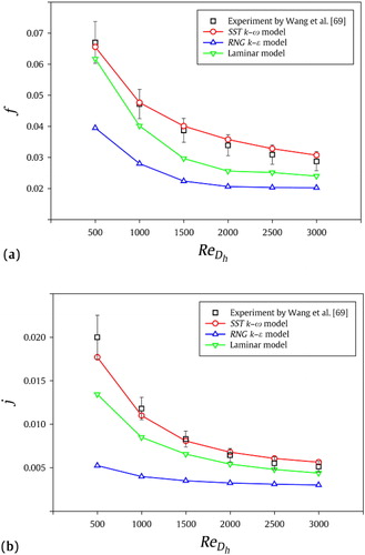
In order to validate the accuracy of the present numerical simulation method, preliminary computational results for a finned heat exchanger were compared with the experimental data reported by Wang et al. [Citation69]. It has to be recalled that the correlations developed by Wang et al. were developed based on 74 samples of plain fin configurations and could describe 88.6% of the experimental database for heat transfer and 85.1% of the experimental database for friction factor within ±15% [Citation69]. In the present investigation, three different models, namely a laminar model, the Re-Normalization Group turbulence model [Citation70] and the SST
turbulence model, were selected to simulate the heat transfer and fluid flow in the dimpled fin channel. As expected, the results of the SST
model compared best with the experimental results over the whole Reynolds number regime discussed in the current investigation. From , the maximum difference between the numerical results and the experimental data for Colburn j factor and friction factor f were found to be less than 13% and 6%, respectively. The agreement between the numerical results and experimental data indicates the reliability of the computational model. Therefore, in the present study, the SST
turbulence model is chosen to simulate the flow in the fin channel with CDTs.
Figure 5. Friction factor f and Colburn j factor comparisons between numerical simulation and experimental results.
In fact no direct experimental results, or even no relevant experimental research studies, about the heat transfer and fluid flow characteristics of FTHEs with dimple/protrusion turbulators are available. However, in order to further validate the reliability of the calculations, numerical results of the normalized average Nusselt number and normalized friction factor
from the SST
turbulence model were compared to the experimental data of Mahmood et al. [Citation71] for a channel with dimples and protrusions. Indeed, Mahmood et al. [Citation71] experimentally studied the thermo-hydraulic performance in a channel with aligned spherical dimples and protrusions on opposite walls in fully turbulent flow regime (
based on the channel height H). It should be noted that the uncertainties of the experimental data of Mahmood et al. [Citation71] have been determined by a standard error analysis and uncertainty estimates are based on 95 percent confidence levels. According to the measurement instruments, the corresponding Nusselt number ratio uncertainty was estimated to be within ±9.6%. For more details, see Ref. [Citation71].
illustrates a schematic representation of the channel geometry with aligned dimples and protrusions used to validate the present numerical simulation. Additional details of the model configuration are given by Ref. [Citation71]. The geometrical parameters of the experimental model including
and
were employed in the validation. In the experiments, a constant heat flux boundary condition is applied to the dimpled surface and an adiabatic wall boundary condition is applied to the protrusion surface. The same boundary conditions are employed in the validation.
Figure 6. Schematic of the channel with aligned dimples and protrusions.
summarizes the results of the comparison between numerical simulations and experimental data. As seen in , the maximum deviation between the numerical results obtained by the current method and the experimental data for normalized average Nusselt number and normalized friction factor
were found to be 9.4% and 8.3%, respectively. The good agreement between the numerical results and experimental data indicates the reliability of the SST
turbulence model in this study.
Table 3. Comparison between numerical simulations and experimental results in the channel with dimples and protrusions.
Computational results and discussion
In this section, the flow physics structure of the compound design are explored in detail, to find out how the innovative CDTs contribute to augment the thermo-hydraulic performance of the finned elliptical tube heat exchanger.
Case study of the influence of tube row numbers
In the enhanced FTHEs, the effect of number of tube rows depends mainly on the tube arrangement, tube shape, value of the Reynolds number and the flow manipulators/turbulators configurations. To investigate the effects of different structural parameters, we further examined the influence of tube row number on the flow and heat transfer characteristics for fin-and-elliptical tube heat exchanger with ED turbulators. Hence, the tube row number varies from 2 to 5.
presents the variation of the average Nusselt number Nu versus the Reynolds number for various tube row numbers. It can be seen that the average Nusselt number Nu decreases with the increasing tube row number. The changing trend of the average Nusselt number Nu is almost the same for different
shows the variation of the friction factor f versus the tube row number. It can be seen that the friction factor f decreases with the increasing tube row number.
Figure 7. Influence of tube row numbers on: (a) average Nusselt number Nu; (b) friction factor f.
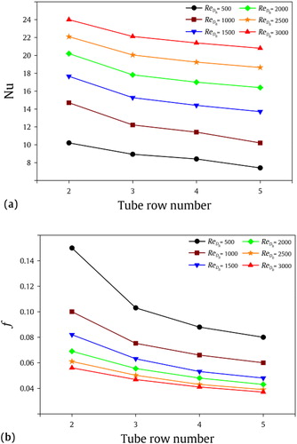
For 3 or more tube rows, the influence of the tube row number on the average Nusselt number Nu and friction factor f becomes smaller and smaller with increasing tube row number. According to the above analysis, it is found that the three-rows of elliptical tubes in staggered arrangement are recommended for practical applications.
Case study of the configuration of CDTs
In a dimpled FTHE, the zone around the tube is of extraordinary importance. Therefore, with respect to the limited space between the elliptical tubes, the best and most appropriate configuration of CDTs for the dimpled fin pattern must be considered. Hence, a comparative investigation of the effect of configuration of the CDTs (e.g. ED) on the heat transfer enhancement and pressure drop in the dimpled FTHE is performed.
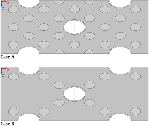
Two arranged manners of the CDT in the fin pattern are considered in this section of the study: cross arrangement and diagonal arrangement (i.e. two CDT pairs are nearby the up- and downstream side of the elliptical tube). Thus two arrangements named Case A and Case B, respectively, are presented in .
Figure 8. Schematics of the two simulated CDTs configurations: cross arrangement (Case A) and diagonal arrangement (Case B).
shows the relation of the average Nusselt number Nu and friction factor f versus the Reynolds number for the two arrangements of CDTs in the fin pattern. From this figure, one can see that at the same Reynolds number the Nusselt number Nu and friction factor f for the Case A is larger than that for the Case B. The influence of the configuration of CDTs on the flow area goodness factor j/f at different Reynolds numbers is shown in . As a consequence, the Case A provides a better overall performance of j/f than the Case B.
Figure 9. Influence of configuration of CDTs on: (a) average Nusselt number Nu and friction factor f; (b) flow area goodness factor j/f.
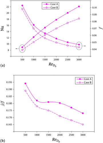
Therefore it is better to increase the thermo-hydraulic performance in a small size finned tube heat exchanger by having the cross arrangement of CDTs in the fin pattern due to further turbulence close to the wall and an increase in heat transfer area.
Case study of the flow pattern and temperature field characteristics
To illuminate the physics of the fluid flow in the airflow passage of the PFET heat exchanger with five innovative CDTs, it is useful to plot the counter-rotating streamwise vortices. demonstrates the predicted surface streamlines of the airflow close to plate fin surface with CDTs for It demonstrates lots of airflow features close to the fin surface responsible for the heat transfer augmentation.
Figure 10. Streamline patterns close the dimpled fin surface for (a) CFD turbulators, (b) ED turbulators, (c) TPD turbulators, (d) LwTD turbulators, and (e) UwTD turbulators, at
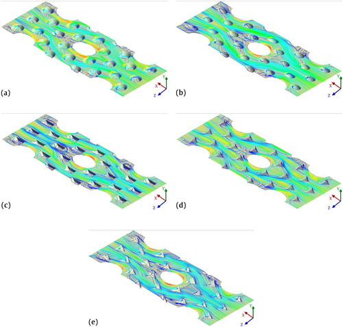
As previously stated, Isaev et al. [Citation48] performed a series of systematic studies for predicting the detailed vortex-jet structures on the dimpled surface with different dimple geometries. They reported that the turbulent flow past deep dimples () becomes asymmetric and friction/heat transfer coefficients increase abruptly, particularly when the Reynolds number increases. On the other hand, Terekhov et al. [Citation33] experimentally examined the flow structures in a dimpled surface. They also showed that the flow in the deep dimples is asymmetric, which the result of a large vortex existing at the leading edge of the dimple.
As is evident from the streamline patterns in , the asymmetrical flow structure mechanism is due to the fact that with increasing flow velocity, the vortex becomes asymmetric with one side larger than the other. The jet from the larger vortex side tries to “push” the jet on the other side out of the dimple and eventually forms a transverse single-cell vortex called a tornado-like vortex. That makes the asymmetric flow around the depth dimple to be accompanied by heat transfer enhancement from the dimple wall on the windward side.
Generally, for the airflow across the dimples located instantly downstream side of each elliptical tube, it seems that one extra strong secondary vortex flow is induced in the upstream halves of the CDT and then it is injected into the wake behind the elliptical tube. Enhancement of the three-dimensional turbulent mixing in the wake region occurs. This phenomenon is clearly shown in the flow patterns as presented in .
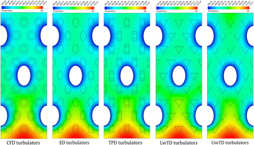
In order to provide a better understanding of the enhanced heat transfer mechanism over the above and nearby the dimples and protrusions, the fluid flow structures and temperature distributions are presented. shows a comparison of the velocity streamlines and temperature contours in the longitudinal central plane in the finned elliptical tube-dimple turbulator channels of different geometric shape of CDTs, which indicates the aligned dimples and protrusions on opposite fin surfaces, at
Figure 11. Velocity streamlines and temperature contours on streamwise cut across the central in the finned elliptical tube-dimple turbulator channels of the (a) CFD turbulators, (b) ED turbulators, (c) TPD turbulators, (d) LwTD turbulators, and (e) UwTD turbulators, at (The schematic diagram above shows the location of the longitudinal central plane (
) in the dimpled PFET heat exchanger with TPD turbulators).
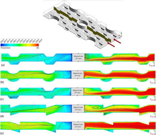
According to a thorough investigation conducted by Elyyan et al. [Citation21], in general, heat transfer intensification on the dimpled surface was mainly brought about by separation induced vortex impingement in the reattachment zone of the concave dimple. Indeed, the departure and redirection of these vortices and additional vortex shedding at the dimple edge were responsible for the high heat transfer intensification on the flat area downstream of the dimple.
In every enhanced case, there are airflow separation and recirculation in the upstream halves of the CDTs, which are liable for the heat transfer decline there. There are airflow rejoining and collision onto the downstream halves of the dimpled wall and secondary flow vortices are shed from the dimples particularly close to the rear rim of the CDTs, all of which contribute to the heat transfer enhancement (see ).
For the triangular CDTs, a pair of counter-rotating streamwise vortices appears from each of the two downstream corners of the dimples, and these counter-rotating streamwise vortices are convected downstream. It is worth mentioning that the vortex intensity resulting from the triangular CDT is greater than for the other CDTs. This is predominantly due to the straight sloped wall in the upstream half of the LwTDs and accordingly the airflow recirculation and separation are distinctively decreased compared to the CDT cases. These flow characteristics explain why the superior heat transfer performance exists in the PFET heat exchanger with LwTD turbulators. Indeed, the lack of a large flow reversal and the flow impingement along the downstream edge of the LwTD turbulator contribute to greater enhancement in the heat transfer on the CDT surface (see ).
On the other hand, on the protrusion side, acceleration between protrusions and flow impingement on the protrusions played a key role in augmenting heat transfer. Wake turbulence also plays an important role in augmenting heat transfer on the flat area downstream of the protrusions in every enhanced case.
demonstrates the computational fluid dynamics results of the streamlines and temperature contours in the vertical cross-sections (
and
from the inlet of model) just after the first, second and third elliptical tube rows at
Figure 12. Streamlines and temperature contours in transverse planes, at
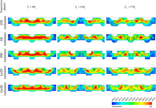
During the longitudinal counter-rotating vortices interaction with the airflow along the mainstream path, a strong three-dimensional swirling flow is formed. Accordingly the mixing of the fluid flow is improved. In general, mixing of the main flow, reduction of the flow boundary layer, raise of the turbulent intensity, creation of rotating and secondary flows are the main reasons for the increase of the heat transfer. From the vertical sections illustrated in , it is evident that the triangular CDTs provides the highest vortex intensity and the number of vortices is higher than for the other CDTs. Actually, it can be seen that the triangular CDTs case generates more counter-rotating vortices and near to the bottom side on the wall.
It can be deduced from these figures that the counter-rotating streamwise vortices lead to deformation of the temperature profiles in the airflow channel. In the first vertical cross-section, which is next to the second CDT arrays, the temperature field has been influenced by the CDT. This is attributed to the fact that the rotating flows wash the dimpled wall, leading to increase of the heat transfer rate. The variations in the temperature profile from the second vertical cross-section to the third vertical cross-section tell us that the counter-rotating streamwise vortices are spreading gradually and create mixing of the fluid in the channel. Indeed, at the plane of considerable temperature changes are found in the near dimple wall region, so that after the 3rd row of elliptical tubes, flow ejection happens with stronger mixing. It is also noticeable that the outlet temperature of the PFET heat exchanger with LwTDs is the lowest compared to the other enhanced cases. This means that the total heat transfer rate of the proposed fin is the highest.
Case study of the flow and heat transfer distributions
The contour plots of the velocity and temperature fields for the cases ED, CFD, TPD, LwTD, and UwTD turbulators on the x–z plane at the middle horizontal plane between two plate fins and on the plate fin surface, respectively, at are illustrated in and .
Figure 13. Local distribution of the velocity (in the middle x–z plane) for the CDTs, at
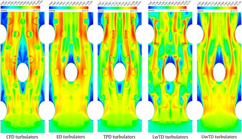
Figure 14. Local distribution of the temperature (in across the plate fin surface) for the CDTs, at
The concave dimple acts as a turbulator to produce several vortex structures and strong upwash airflow in the boundary layer flow over the dimpled fin surface to promote the turbulent mixing between the high-speed airflow and the low-speed flow inside the dimple cavity. The velocity contours reveal clearly that the high-speed mainstream airflow would shift downward slightly and impinge onto the back rim/edge of the dimple, creating strong upwash airflow close the back rim/edge of the CDT.
Temperature contours indicate that the heat transfer performance in the wake region is improved and the airflow temperature decreases rapidly in the main flow direction. However, the fluid temperature of the outlet region is increased. Therefore, the heat transfer coefficient of the air-side for the PFET heat exchanger with CDTs is increased because the increase of the total heat transfer rate. In addition, it is found that the temperature distributions near the downstream CDTs are usually uniform. This is attributed to the progressively streamwise development of the boundary layer.
An attempt to provide further details on the convective heat transfer characteristics on the dimpled fin surfaces with diverse dimple turbulator shapes is shown in to here comparisons of the computational fluid dynamics results of the local Nusselt number Nu distribution on the plate fin surfaces for the cases ED, CFD, TPD, LwTD, and UwTD turbulators are depicted at It is worth mentioning that for a dimpled fin surfaces, because the airflow is frequently interrupted close to the dimpled fin surface, the flow structures close to the dimpled fin surface are significantly different from that for a smooth plate fin surface. It is well perceived that the heat transfer in the wake regions behind the tubes is always relatively weak due to recirculation and the vortex. Therefore, the wake region should be reduced as much as possible. The horseshoe vortices formed in the elliptical tube stagnation region are swept downstream along the side of the elliptical tube as a longitudinal vortex.
Figure 15. Local distribution of the Nusselt number (in across the plate fin surface) for the CDTs, at
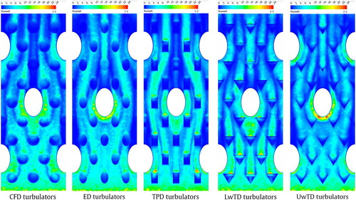
In every enhanced case, due to the thermal entrance airflow effects, it is evident that the maximum value of average Nusselt number Nu occurs at the leading edge of the dimpled plates and then decreases rapidly in the streamwise direction as a consequence of the thermal boundary layer effect. However, locally high Nusselt number Nu regions were observed in front of each elliptical tube. This indicates that horseshoe vortices are formed and the downwash augments heat transfer in the regions.
It can be seen that for the entire enhanced cases of dimple turbulators, the upstream half of the dimpled fin surface illustrates reduced heat-transfer rates as the airflow recirculates and separates inside the dimple. The extent of the recirculation region inside the dimple shrinks as the airflow becomes more turbulent. But conversely, the convective heat transfer is significantly augmented in the downstream halves of the dimpled surface and in the downstream region of the dimple turbulators, particularly closes to the rear rim/edge of the dimples. This appears as the counter-rotating secondary flow vortices shed from the dimple turbulators dramatically intensify the turbulent airflow mixing level in the near-downstream wall flow area in the finned elliptical tube-dimple turbulator channels. Furthermore the considerable Nusselt number enhancement close to the downstream dimple rims/edges is due to the induced local instabilities and shear layer reattachment and acceleration. This is most obvious for the low and medium Reynolds number flows.
In the case of the effect of dimple shape, shows that the fin surface with the LwTD turbulators acquires a distinctively higher local heat transfer enhancement, and due to the straight slope of the upstream dimpled wall the low heat transfer area in this area is apparently reduced. The non-availability of a massive airflow overturns and the airflow collision along the downstream rim of the LwTD assists in the greater enhancement of the heat transfer on the dimple turbulator surface.
Case study of the thermal and hydrodynamic characteristics
To study the influence of the new CDTs on the characteristics of thermal and flow fields for PFET heat exchangers, a comparative investigation for PFET heat exchangers with CDTs and without CDTs was accomplished. The PFET heat exchanger without CDTs will be referred to as “baseline” (un-enhanced) case and the PFET heat exchanger with CDTs will be referred to as “enhanced” cases. shows the variation of the average Nusselt number Nu versus Reynolds number One may observe from that the average Nusselt number Nu for both the baseline case and the five enhanced cases increases with increasing Reynolds number. The average Nusselt number Nu of the PFET heat exchangers with CDTs is larger than that of the baseline case at different Reynolds numbers.
Figure 16. Influence of type of CDTs on average Nusselt number Nu.
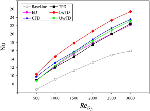
shows the variation of the average Nusselt number Nu versus the Reynolds number for the five new CDT test cases. From this figure, it can be clearly observed that the average Nusselt numbers Nu for the enhanced case LwTD turbulators are larger than those for the enhanced cases with other geometric shapes in the whole range of Reynolds number. This result indicates that the LwTD turbulators provide better effectiveness of the heat transfer enhancement.
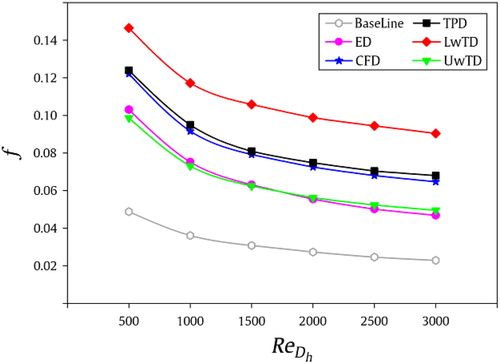
provides the relation of the friction factor f and the Reynolds number It is observed that f decreases with an increase in
for all CDTs investigated. It can be clearly seen that for the LwTD turbulators arrangement, the friction factor f is greater than that for the other CDTs. Nevertheless, LwTD turbulators in addition to enhancing the heat transfer of the PFET heat exchanger they also result in an extra pressure drop due to its special structural shape, but the UwTDs and EDs cases have the smallest friction factor f at the same Reynolds number.
Figure 17. Influence of type of CDTs on friction factor f.
In this section, with the aim of investigating the influence of the longitudinal counter-rotating vortices generated by the dimple turbulators on the heat transfer of the elliptical tube surface, depicts the variation of the span-averaged tube surface heat flux along the circumference of the elliptical tube from the second row tube for both the five enhanced cases and the baseline case, at It should be noted that the angle α is determined from the front stagnation point of the elliptical tube.
Figure 18. Span-averaged tube surface heat flux along tube circumference, at
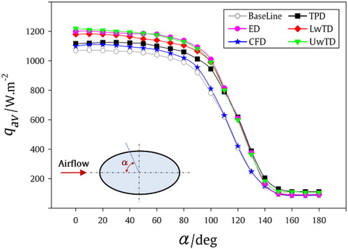
It is observed in that the local heat flux has a maximum value at the front stagnation point of the elliptical tube, and gradually decreases with increasing circumferential angle. Also it is clear from this figure that the effect of the vortices generated by each type of CDTs on the heat flux at the front stagnation point of the tube is somewhat different. When the circumferential angle is larger than about 110°, the flow separation occurs at the rear portion of the tube and the wake region is formed behind the tube, the tube surface is covered by the wake flow, the local heat flux is quickly decreased. From this figure, it can be seen that the span-averaged tube surface heat flux for the case UwTDs is larger than those for the enhanced cases, particularly before developing the wake region.
Case study of the secondary flow characteristics
The longitudinal vortices interact with an otherwise two-dimensional boundary layer and produce a three-dimensional swirling flow that mixes the near-wall fluid with the free stream. In general, mixing with the main flow, reducing the flow boundary layer, raising the turbulent intensity, creating rotating and secondary flow are the main reasons for the increase of the heat transfer.
A comparison of the average secondary flow intensity Se as a function of Reynolds number for all the cases are shown in . It can be seen that the average secondary flow intensity Se for both the baseline case and the five enhanced cases increases with increasing Reynolds number.
Figure 19. Influence of type of CDTs on average secondary flow intensity Se.
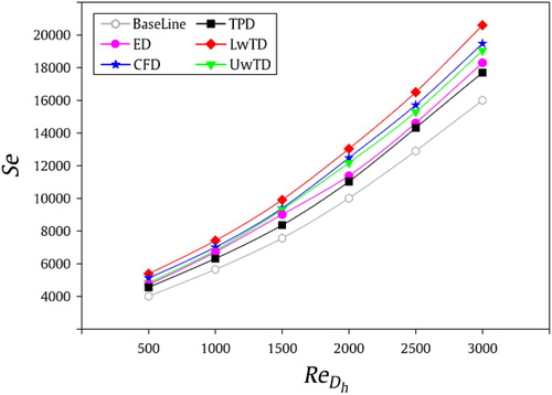
The value of Se in the dimpled fin cases is larger than that of the plate fin model at the same This clearly shows that the leeward triangular dimpled fin surface plays an important role in inducing the secondary flow, which results in heat transfer enhancement on the fin surfaces. Also, it can be realized that the distribution of the average Se has similar trends as the average Nu.
Performance evaluation criterion
Performance evaluation of a compact heat exchanger is a complicated subject, which depends on several factors as there is no unique definition. Consequently, Shah and Sekulić [Citation72] stated that there are 16 performance evaluation criteria.
The ratio of Colburn j factor and the friction factor f, versus Reynolds number, is generally known as the “flow area goodness factor.” The flow area goodness factor is utilized to optimize the finned tube heat exchanger frontal area. Accordingly, a maximum value of the flow area goodness factor demonstrates a minimum frontal area of the finned tube heat exchanger. Therefore, for a specified operating condition, a higher j/f indicates a lower frontal area. The frontal area parameter of the PFET heat exchanger is the parameter of consideration here. Therefore the flow area goodness factor is compared for the PFET heat exchanger with new type of CDTs. shows the relative PEC of the PFET heat exchanger versus CDTs. It was observed in , that the ratios of j/f decrease with the increase of Reynolds number. For the enhanced cases CDTs studied, the ratio of efficiency index j/f for UwTDs case is higher than that of the other enhanced cases, so that, the maximum enhancement in j/f ratio at the highest Reynolds number is about 65%.
Figure 20. Flow area goodness factor (a) and core volume goodness factor (b) for CDTs.
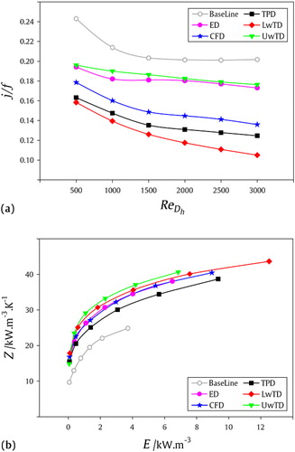
On the other hand, the PEC of the finned tube heat exchanger is determined and analyzed by the “core volume goodness factor.” A high value of the heat transfer power per unit temperature and per unit volume (Z) with respect to the fan power per unit core volume (E) demonstrates a more compact heat exchanger and the parameters such as pressure drop, fluid flow rate, heat transfer rate and temperature difference between the fluid flow and the surface are kept constant. From the viewpoint of the finned tube heat exchanger volume needed, geometries with larger values of Z will require less core volume for a given air-side heat transfer capacity. illustrates the volume goodness factor for different enhanced cases CDTs, and it can be realized that the UwTDs case has a higher value than the other enhanced cases.
PEC comparison: influence of enhanced fin patterns
As is well known, the heat transfer performance of FTHEs is highly dependent on the structure of the fins because the dominant thermal resistance is generally on the air-side. The purpose of next generation compact heat exchangers is to increase the thermo-hydraulic performance due to combined enhancement techniques and thereby improve the energy-efficiency. Hence, currently, the utilization of enhanced fin patterns is very appropriate in advanced FTHEs.
In order to reveal the importance of this issue, a number of enhanced FTHEs were compared, namely – louvered FTHE [Citation73], herringbone wavy FTHE [Citation74], smooth wavy FTHE with two types of vortex generators at small and large attack angles [Citation9] and PFET heat exchanger with UwTD turbulators (i.e. present study), with similar geometrical parameters, by two key performance evaluation criteria, i.e. flow area goodness factor and core volume goodness factor. The results of these comparisons are presented in .
Figure 21. PEC comparison of a number of enhanced FTHEs: (a) (b)
Notice that all datasets were acquired under the same conditions and basic geometrical configurations.
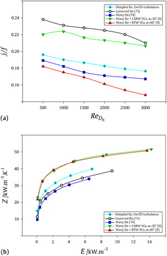
It can be seen that the louvered FTHE and wavy FTHE with curved angle rectangular winglet vortex generators at small attack angles have better flow area goodness factor due to lower friction factor than the other enhanced cases. An overview of reveals that the wavy FTHE with vortex generators and the PFET heat exchanger with UwTD turbulators have higher core volume goodness factor than the other enhanced cases.
An important point should be noted, that the present comparison is provided solely for an individual kind of finned tube heat exchanger geometry (as stated in Ref. [Citation9] and present study), and by changing the design parameters such as the longitudinal and transverse tube pitch, tube diameter and fin pitch, etc., effectiveness of the flow manipulators and turbulators on the thermo-hydraulic performance can be different and thus the comparison of the results will also be changed.
In future works, further research needs to be carried out to develop correlations, in a wide range of geometric dimensions, for heat transfer and fluid flow in enhanced FTHEs with the flow manipulators/turbulators, in order to provide a precise and comprehensive comparison between the enhanced FTHEs.
Concluding remarks
This paper presents results of three-dimensional computational fluid dynamics simulations of the thermo-hydraulic characteristics of the PFET heat exchangers with an innovative type of CDTs taking into account all geometric characteristics. The various CDTs investigated are ED, CFD, TPD, LwTD, and UwTD. The computational results are analyzed by considering the performance evaluation criterion. Some of the remarkable conclusions are as follows:
Results reveal clearly that the high-speed mainstream airflow would shift downward slightly and impinge onto the back rim/edge of the dimple, creating strong upwash airflow close to the back rim/edge of the CDT, which reinforce local magnitudes of eddy diffusivity for heat and momentum.
It is found that the largest augmentations of heat transfer over the largest airflow volumes are created by LwTD turbulators. This is due to the fact that by shifting the deepest part of the dimple turbulator downstream provides stronger secondary vortices and near to the downstream rim wall of LwTD turbulator. Hence better heat transfer performance is achieved.
As mentioned, it is a fact that decreasing the recirculation zone inside the upstream dimple turbulator can augment the heat transfer rate, as well as in contrary, even reduce the pressure drop. Accordingly, UwTD turbulators were successful in improving the enhancement of the thermo-hydraulic performance due to its special structural shape in both upstream and downstream regions of UwTD turbulators, which makes the flow impinge on the downstream stronger.
| Nomenclature | ||
| A | = | cross-sectional area (m2) |
| = | minimum flow cross-sectional area (m2) | |
| = | fin surface area (m2) | |
| = | total heat-transfer surface area (m2) | |
| = | specific heat of fluid (J/kg-K) | |
| CDT | = | concave dimple turbulator |
| CFD | = | conical frustum dimple |
| = | hydraulic diameter (m) | |
| = | dimple printed diameter (m) | |
| = | diameter of conical frustum dimple at bottom section (m) | |
| e | = | tube ellipticity ratio |
| E | = | fan power per unit core volume (W/m3) |
| ED | = | elliptical dimple |
| f | = | friction factor |
| FTHE | = | fin-and-tube heat exchanger |
| = | fin pitch (m) | |
| h | = | heat transfer coefficient (W/m2-K) |
| H | = | channel height defined in (m) |
| = | dimple depth (m) | |
| HVAC&R | = | heating, ventilation, air-conditioning & refrigeration |
| j | = | Colburn factor |
| LwTD | = | leeward triangular dimple |
| = | mass flow rate (kg/s) | |
| = | unit surface normal vector | |
| Nu | = | Nusselt number |
| p | = | pressure (Pa) |
| PEC | = | performance evaluation criteria |
| PFET | = | plain fin-and-elliptical tube |
| Pr | = | Prandtl number |
| = | longitudinal tube pitch (m) | |
| = | transverse tube pitch (m) | |
| = | heat flux (W/m2) | |
| = | area-averaged heat flux (W/m2) | |
| = | semi-major diameter of elliptical tube (m) | |
| = | semi-minor diameter of elliptical tube (m) | |
| = | Reynolds number based on hydraulic diameter | |
| = | Reynolds number based on channel height | |
| RANS | = | Reynolds-averaged Navier–Stokes |
| S | = | dimple/protrusion streamwise pitch defined in (m) |
| Se | = | intensity of secondary flow |
| = | local average intensity of secondary flow | |
| SST | = | shear-stress transport |
| T | = | temperature (K) |
| TPD | = | trapezoidal prism dimple |
| u | = | fluid velocity magnitude (m/s) |
| = | maximum average velocity at minimum flow cross-sectional area (m/s) | |
| = | average velocity in streamwise direction (m/s) | |
| U | = | fluid velocity vector |
| UwTD | = | upward triangular dimple |
| V | = | volume of the computational domain (m3) |
| = | width of non-globular dimple (m) | |
| = | width of trapezoidal prism dimple at bottom section (m) | |
| x, y, z | = | Cartesian coordinates |
| y | = | vertical distance normal to wall direction defined in EquationEq. (6) |
| = | dimensionless distance from wall | |
| Yi, Yii, Yiii | = | vertical cross-sections in y-direction ( |
| Z | = | heat transfer power per unit temperature and per unit volume (W/m3-K) |
| Greek symbols | ||
| = | incline angle defined in (°) | |
| = | coefficient defined in EquationEq. (6) | |
| δ | = | fin thickness (m) |
| Δp | = | pressure drop in flow direction (Pa) |
| ΔT | = | temperature difference (K) |
| Δx | = | dimple streamwise pitch (m) |
| Δz | = | dimple spanwise pitch (m) |
| = | dissipation rate of turbulence energy (m2/s3) | |
| = | fin efficiency | |
| = | overall surface effectiveness | |
| κ | = | turbulent kinetic energy (m2/s2) |
| λ | = | thermal conductivity (W/m-K) |
| μ | = | dynamic viscosity (kg/s-m) |
| = | kinematic viscosity (m2/s) | |
| ρ | = | density (kg/m3) |
| = | contraction ratio of cross-sectional area | |
| = | turbulent Prandtl number for kinetic energy | |
| = | turbulent Prandtl number for energy dissipation rate | |
| = | wall shear stress (Pa) | |
| ω | = | turbulence frequency (1/s) |
| = | vorticity (1/s) | |
| Subscripts | ||
| 0 | = | smooth channel without dimple/protrusion |
| eff | = | effective |
| f | = | fin, fin surface |
| in | = | air-side inlet |
| lm | = | logarithmic mean |
| out | = | air-side outlet |
| t | = | turbulent |
| w | = | tube wall |
| x | = | local value |
| Superscript | ||
| n | = | direction normal to the cross section |
Acknowledgments
This work was carried out at the Heat Transfer Group at the Department of Energy Sciences, Lund University by Dr. Babak Lotfi as a research affiliate under the supervision of Professor Bengt Sundén.
Additional information
Babak Lotfi is a Research Affiliate in the Heat Transfer Group at the Department of Energy Sciences, Lund University, Sweden. He received his Ph.D. in Power Engineering and Engineering Thermophysics from Xi’an Jiaotong University in 2015. His research activities include advanced compact heat exchangers, enhancement of heat transfer, fluid–structure interaction, multi–scale transport phenomena and turbulence modeling. He is an author or coauthor of several peer review scientific journal papers and international conference papers.
Bengt Sundén received his M.Sc. in Mechanical Engineering 1973, Ph.D. in Applied Thermodynamics and Fluid Mechanics 1979, became Docent in Applied Thermodynamics and Fluid Mechanics 1980, all at Chalmers University of Technology, Göteborg, Sweden. He was Professor of Heat Transfer, Lund University, Lund, Sweden 1992–2016, Head Department of Energy Sciences, Lund University, Lund, Sweden for 21 years, 1995–2016. He serves as Professor Emeritus and Senior Professor in Heat Transfer since 2016-10-01. The research activities cover compact heat exchangers, heat transfer enhancement, gas turbine heat transfer, combustion-related heat transfer including thermal radiation, CFD-methods, liquid crystal thermography, condensation and evaporation on micro-nanostructured surfaces, nanofluids, impinging jets, aerospace heat transfer, computational modeling and analysis of multiphysics and multiscale phenomena for fuel cells (SOFC, SOEC, PEMFC). He was founding and first editor-in-chief IJHEX – International Journal of Heat Exchangers (R.T. Edwards Inc., USA) 1999–2008, Associate Editor ASME J. Heat Transfer 2005–2008, Editor-in-chief Book Series – Developments in Heat Transfer (WIT Press, UK), 1995-, published more than 800 papers in journals (>350), books, proceedings, supervised 180 M.Sc. theses, 50 Licentiate of Engineering theses, 48 PhD-theses, Fellow of ASME, Honorary Professor Xi’an Jiaotong Univ., China, Guest Professor Northwestern Polytechnical Univ., Xi’an, China, Guest Professor Harbin Institute of Technology, Harbin, China, 2011 Recipient of ASME Heat Transfer Memorial Award, 2013 recipient of ASME Heat Transfer Division 75th Anniversary Medal, Donald Q. Kern Award 2016, Regional editor Journal of Enhanced Heat Transfer 2007-, Associate editor J. Heat Transfer Research 2011-, Associate editor ASME J. Thermal Science, Engineering and Applications 2010-2016, Associate editor ASME J. Electrochemical Energy Conversion and Storage 2017–2020.
References
- D. E. Newton, World Energy Crisis: A Reference Handbook. Santa Barbara, CA: ABC-CLIO, 2013.
- R. L. Webb, Principles of Enhanced Heat Transfer. New York: John Wiley & Sons, 1994.
- R. L. Webb, “Air-side heat transfer in finned tube heat exchangers,” Heat Transf. Eng., vol. 1, no. 3, pp. 33–49, 1980. DOI: 10.1080/01457638008939561.
- L. A. O. Rocha, F. E. M. Saboya, and J. V. C. Vargas, “A comparative study of elliptical and circular sections in one- and two-row tubes and plate fin heat exchangers,” Int. J. Heat Fluid Flow, vol. 18, no. 2, pp. 247–252, 1997. DOI: 10.1016/S0142-727X(96)00063-X.
- A. Hasan, and K. Siren, “Performance investigation of plain circular and oval tube evaporative cooled heat exchangers,” Appl. Thermal Eng., vol. 24, no. 5–6, pp. 777–790, 2004. DOI: 10.1016/j.applthermaleng.2003.10.022.
- R. K. Shah, and R. L. Webb, “Compact and enhanced heat exchangers,” in Heat Exchangers: Theory and Practice, J. Taborek, G. F. Hewitt, and N. Afgan, Eds. Washington DC, USA: Hemisphere/McGraw-Hill, 1983, pp. 425–468.
- A. M. Jacobi, and R. K. Shah, “Heat transfer surface enhancement through the use of longitudinal vortices: A review of recent progress,” Exp. Therm. Fluid Sci., vol. 11, no. 3, pp. 295–309, 1995. DOI: 10.1016/0894-1777(95)00066-U.
- L.-H. Tang, S.-C. Tan, P.-Z. Gao, and M. Zeng, “Parameters optimization of fin-and-tube heat exchanger with a novel vortex generator fin by Taguchi method,” Heat Transf. Eng., vol. 37, no. 3–4, pp. 369–381, 2016. DOI: 10.1080/01457632.2015.1052715.
- B. Lotfi, M. Zeng, B. Sundén, and Q. Wang, “3D numerical investigation of flow and heat transfer characteristics in smooth wavy fin-and-elliptical tube heat exchangers using new type vortex generators,” Energy, vol. 73, pp. 233–257, 2014. DOI: 10.1016/j.energy.2014.06.016.
- B. Lotfi, M. Zeng, B. Sundén, and Q. Wang, “Thermo-hydraulic characterization of the smooth wavy fin-and-elliptical tube heat exchangers using new type vortex generators,” Energy Procedia, vol. 61, pp. 2343–2346, 2014. DOI: 10.1016/j.egypro.2014.11.1199.
- B. Lotfi, B. Sundén, and Q. Wang, “An investigation of the thermo-hydraulic performance of the smooth wavy fin-and-elliptical tube heat exchangers utilizing new type vortex generators,” Appl. Energy, vol. 162, pp. 1282–1302, Jan. 2016. DOI: 10.1016/j.apenergy.2015.07.065.
- B. Lotfi, B. Sundén, and Q. Wang, “3D fluid-structure interaction (FSI) simulation of new type vortex generators in smooth wavy fin-and-elliptical tube heat exchanger,” Eng. Computations, vol. 33, no. 8, pp. 2504–2529, 2016. DOI: 10.1108/EC-04-2015-0091.
- S. Mao, N. Love, A. Leanos, and G. Rodriguez-Melo, “Correlation studies of hydrodynamics and heat transfer in metal foam heat exchangers,” Appl. Thermal Eng., vol. 71, no. 1, pp. 104–118, 2014. DOI: 10.1016/j.applthermaleng.2014.06.035.
- R. A. Mahdi, H. A. Mohammed, K. M. Munisamy, and N. H. Saeid, “Review of convection heat transfer and fluid flow in porous media with nanofluid,” Renew Sust. Energy Rev., vol. 41, pp. 715–734, Jan. 2015. DOI: 10.1016/j.rser.2014.08.040.
- G. I. Mahmood et al., “Local heat transfer and flow structure on and above a dimpled surface in a channel,” J. Turbomach., vol. 123, no. 1, pp. 115–123, 2001. DOI: 10.1115/1.1333694.
- G. I. Mahmood, and P. M. Ligrani, “Heat transfer in a dimpled channel: combined influences of aspect ratio, temperature ratio, Reynolds number, and flow structure,” Int. J. Heat Mass Transf., vol. 45, no. 10, pp. 2011–2020, 2002. DOI: 10.1016/S0017-9310(01)00314-3.
- A. Dixit, and A. K. Patil, “Heat transfer characteristics of grooved fin under forced convection,” Heat Transf. Eng., vol. 36, no. 16, pp. 1409–1416, 2015. DOI: 10.1080/01457632.2015.1003726.
- M. R. Maschmann, and H. B. Ma, “An investigation of capillary flow effect on condensation heat transfer on a grooved plate,” Heat Transf. Eng., vol. 27, no. 3, pp. 22–31, 2006. DOI: 10.1080/01457630500454939.
- C. O. Olsson, and B. Sundén, “Thermal and hydraulic performance of a rectangular duct with multiple V-shaped ribs,” ASME J. Heat Transf., vol. 120, no. 4, pp. 1072–1077, 1998. DOI: 10.1115/1.2825892.
- P. Promvonge, T. Chompookham, S. Kwankaomeng, and C. Thianpong, “Enhanced heat transfer in a triangular ribbed channel with longitudinal vortex generators,” Energy Convers. Manage., vol. 51, no. 6, pp. 1242–1249, 2010. DOI: 10.1016/j.enconman.2009.12.035.
- M. A. Elyyan, A. Rozati, and D. K. Tafti, “Investigation of dimpled fins for heat transfer enhancement in compact heat exchangers,” Int. J. Heat Mass Transf., vol. 51, no. 11-12, pp. 2950–2966, 2008. DOI: 10.1016/j.ijheatmasstransfer.2007.09.013.
- J. F. Fan, W. K. Ding, Y. L. He, and W. Q. Tao, “Three-dimensional numerical study of fluid and heat transfer characteristics of dimpled fin surfaces,” Numer. Heat Transf., Part A: Appl., vol. 62, no. 4, pp. 271–294, 2012. DOI: 10.1080/10407782.2012.666931.
- J.-C. Han, “Recent studies in turbine blade cooling,” Int. J. Rotating Mach., vol. 10, no. 6, pp. 443–457, 2004. DOI: 10.1155/S1023621X04000442.
- J.-C. Han, “Fundamental gas turbine heat transfer,” J. Therm. Sci. Eng. Appl., vol. 5, no. 2, pp. TSEA-12-1176, 2013.
- A. Kumar, J. L. Bhagoria, and R. M. Sarviya, “Heat transfer and friction correlations for artificially roughened solar air heater duct with discrete W-shaped ribs,” Energy Convers. Manage., vol. 50, no. 8, pp. 2106–2117, 2009. DOI: 10.1016/j.enconman.2009.01.025.
- T. Alam, R. P. Saini, and J. S. Saini, “Effect of circularity of perforation holes in V-shaped blockages on heat transfer and friction characteristics of rectangular solar air heater duct,” Energy Convers. Manage., vol. 86, pp. 952–963, Oct. 2014. DOI: 10.1016/j.enconman.2014.06.050.
- S. W. Chang, S. F. Chiou, and S. F. Chang, “Heat transfer of impinging jet array over concave-dimpled surface with applications to cooling of electronic chipsets,” Exp. Thermal Fluid Sci., vol. 31, no. 7, pp. 625–640, 2007. DOI: 10.1016/j.expthermflusci.2006.06.008.
- G.-L. Wang et al., “Heat transfer and friction characteristics of the microfluidic heat sink with variously-shaped ribs for chip cooling,” Sensors, vol. 15, no. 4, pp. 9547–9562, 2015. DOI: 10.3390/s150409547.
- R. J. Firth, and L. Meyer, “A comparison of the heat transfer and friction factor performance of four different types of artificially roughened surface,” Int. J. Heat Mass Transf., vol. 26, no. 2, pp. 175–183, 1983. DOI: 10.1016/S0017-9310(83)80024-6.
- S. K. Sharma, and V. R. Kalamkar, “Thermo-hydraulic performance analysis of solar air heaters having artificial roughness – A review,” Renew. Sust. Energ. Rev., vol. 41, pp. 413–435, Jan. 2015. DOI: 10.1016/j.rser.2014.08.051.
- P. M. Ligrani, M. M. Oliveira, and T. Blaskovich, “Comparison of heat transfer augmentation techniques,” AIAA J., vol. 41, no. 3, pp. 337–362, 2003. DOI: 10.2514/2.1964.
- R. S. Snedeker, and C. D. Donaldson, “Observation of a bistable flow in a hemispherical cavity,” AIAA J., vol. 4, no. 4, pp. 735–736, 1966.
- V. I. Terekhov, S. V. Kalinina, and Y. M. Mshvidobadze, “The effects of geometric and dynamic flow parameters on heat transfer in a spherical cavity,” Russian J. Eng. Thermophys., vol. 11, no. 2, pp. 153–166, 2002.
- V. I. Terekhov, S. V. Kalinina, and Y. M. Mshvidobadze, “Heat transfer coefficient and aerodynamic resistance on a surface with a single dimple,” J. Enhanced Heat Transf., vol. 4, no. 2, pp. 131–145, 1997. DOI: 10.1615/JEnhHeatTransf.v4.i2.60.
- V. N. Afanasyev, Ya, P. Chudnovsky, A. I. Leontiev, and P. S. Roganov, “Turbulent flow friction and heat transfer characteristics for spherical cavities on a flat plate,” Exp. Thermal Fluid Sci., vol. 7, no. 1, pp. 1–8, 1993. DOI: 10.1016/0894-1777(93)90075-T.
- M. S. Varun, and N. S. Thakur, “Correlations for solar air heater duct with dimpled shape roughness elements on absorber plate,” Solar Energy, vol. 86, no. 9, pp. 2852–2861, 2012.
- R. P. Saini, and J. Verma, “Heat transfer and friction factor correlations for a duct having dimple-shape artificial roughness for solar air heaters,” Energy, vol. 33, no. 8, pp. 1277–1287, 2008. DOI: 10.1016/j.energy.2008.02.017.
- C. Bi, G. H. Tang, and W. Q. Tao, “Heat transfer enhancement in mini-channel heat sinks with dimples and cylindrical grooves,” Appl. Thermal Eng., vol. 55, no. 1-2, pp. 121–132, 2013. DOI: 10.1016/j.applthermaleng.2013.03.007.
- G. N. Xie, B. Sundén, and W. H. Zhang, “Comparisons of pins/dimples/protrusions cooling concepts for an internal blade tip-wall at high Reynolds numbers,” ASME J. Heat Transf., vol. 133, no. 6, pp. 061902–0619029, 2011. DOI: 10.1115/1.4003558.
- S. D. Hwang, H. G. Kown, and H. H. Cho, “Local heat transfer and thermal performance on periodically dimple–protrusion patterned walls for compact heat exchangers,” Energy, vol. 35, no. 12, pp. 5357–5364, 2010. DOI: 10.1016/j.energy.2010.07.022.
- S. D. Hwang, H. G. Kown, and H. H. Cho, “Heat transfer with dimple/protrusion arrays in a rectangular duct with a low Reynolds number range,” Int. J. Heat Fluid Flow, vol. 29, no. 4, pp. 916–926, 2008. DOI: 10.1016/j.ijheatfluidflow.2008.01.004.
- P. M. Ligrani, J. L. Harrison, G. I. Mahmood, and M. L. Hill, “Flow structure due to dimple depressions on a channel surface,” Phys. Fluids, vol. 13, no. 11, pp. 3442–3451, 2001. DOI: 10.1063/1.1404139.
- P. M. Ligrani, G. I. Mahmood, J. L. Harrison, C. M. Clayton, and D. L. Nelson, “Flow structure and local Nusselt number variations in a channel with dimples and protrusions on opposite walls,” Int. J. Heat Mass Transf., vol. 44, no. 23, pp. 4413–4425, 2001. DOI: 10.1016/S0017-9310(01)00101-6.
- P. M. Ligrani, N. K. Burgess, and S. Y. Won, “Nusselt numbers and flow structure on and above a shallow dimpled surface within a channel including effects of inlet turbulence intensity level,” J. Turbomach., vol. 127, no. 2, pp. 321–330, 2005. DOI: 10.1115/1.1861913.
- J. Park, and P. M. Ligrani, “Numerical predictions of heat transfer and fluid flow characteristics for seven different dimpled surfaces in a channel,” Numer. Heat Transf., Part A: Appl., vol. 47, no. 3, pp. 209–232, 2005. DOI: 10.1080/10407780590886304.
- H. Lienhart, M. Breuer, and C. Köksoy, “Drag reduction by dimples? – A complementary experimental/numerical investigation,” Int. J. Heat Fluid Flow, vol. 29, no. 3, pp. 783–791, 2008. DOI: 10.1016/j.ijheatfluidflow.2008.02.001.
- M. K. Chyu, Y. Yu, H. Ding, J. P. Downs, and F. O. Soechting, “Concavity enhanced heat transfer in an internal cooling passage,” ASME Int. Gas Turbine and Aeroengine Congr. and Exhibition. Orlando, FL, USA: ASME, p. 97-GT-437, June 2–5, 1997.
- S. A. Isaev, A. I. Leont’ev, P. A. Baranov, K. T. Metov, and A. E. Usachov, “Numerical analysis of the effect of viscosity on the vortex dynamics in laminar separated flow past a dimple on a plane with allowance for its asymmetry,” J. Eng. Phys. Thermophys., vol. 74, no. 2, pp. 339–346, 2001. DOI: 10.1023/A:1016600404896.
- S. A. Isaev, A. I. Leont’ev, K. T. Metov, and V. B. Kharchenko, “Modeling of the influence of viscosity on the tornado heat exchange in turbulent flow around a small hole on the plane,” J. Eng. Phys. Thermophys., vol. 75, no. 4, pp. 890–898, 2002. DOI: 10.1023/A:1020315118820.
- S. A. Isaev, A. I. Leont’ev, P. A. Baranov, and I. A. Pyshnyi, “Numerical analysis of the influence of the depth of a spherical hole on a plane wall on turbulent heat exchange,” J. Eng. Phys. Thermophys., vol. 76, no. 1, pp. 61–69, 2003. DOI: 10.1023/A:1022911123758.
- H. K. Moon, T. O’Connell, and R. Sharma, “Heat transfer enhancement using a convex-patterned surface,” J. Turbomach., vol. 125, no. 2, pp. 274–280, 2003. DOI: 10.1115/1.1556404.
- S. Y. Won, Q. Zhang, and P. M. Ligrani, “Comparisons of flow structure above dimpled surfaces with different dimple depths in a channel,” Phys. Fluids, vol. 17, no. 4, pp. 045105–045109, 2005. DOI: 10.1063/1.1872073.
- Y. Chen, Y. T. Chew, and B. C. Khoo, “Enhancement of heat transfer in turbulent channel flow over dimpled surface,” Int. J. Heat Mass Transf., vol. 55, no. 25–26, pp. 8100–8121, 2012. DOI: 10.1016/j.ijheatmasstransfer.2012.08.043.
- J. Turnow, N. Kornev, V. Zhdanov, and E. Hassel, “Flow structures and heat transfer on dimples in a staggered arrangement,” Int. J. Heat Fluid Flow, vol. 35, pp. 168–175, June 2012. DOI: 10.1016/j.ijheatfluidflow.2012.01.002.
- C. M. Tay, Y. T. Chew, B. C. Khoo, and J. B. Zhao, “Development of flow structures over dimples,” Exp. Thermal Fluid Sci., vol. 52, pp. 278–287, Jan. 2014. DOI: 10.1016/j.expthermflusci.2013.10.001.
- Y. Rao, Y. Feng, B. Li, and B. Weigand, “Experimental and numerical study of heat transfer and flow friction in channels with dimples of different shapes,” ASME J. Heat Transf., vol. 137, no. 3, pp. 031901–031910, 2015. DOI: 10.1115/1.4029036.
- H.-M. Kim, M.-A. Moon, and K.-Y. Kim, “Multi-objective optimization of a cooling channel with staggered elliptic dimples,” Energy, vol. 36, no. 5, pp. 3419–3428, 2011. DOI: 10.1016/j.energy.2011.03.043.
- S. Farokhi, and R. R. Taghavi, “Supersonic vortex generator,” U.S. Patent 55,989,90A, Feb. 4, 1997.
- F. R. Menter, “Two-equation eddy-viscosity turbulence models for engineering applications,” AIAA J., vol. 32, no. 8, pp. 1598–1605, 1994. DOI: 10.2514/3.12149.
- F. R. Menter, M. Kuntz, and R. Langtry, “Ten years of industrial experience with the SST turbulence model,” Proc. of the 4th Int. Symp. on Turbulence, Heat and Mass Transf. Antalya, Turkey, pp. 625–632, Oct. 12–17, 2003.
- J. E. Bardina, P. G. Huang, and T. J. Coakley, “Turbulence modeling validation, testing, and development,” NASA Ames Research Center, Moffett Field, CA, USA, Rep. NASA-TM-110446, April, 1997.
- ANSYS CFX, Solver Theory Guide Release 16.0. Canonsburg, PA, USA: ANSYS Inc., 2014.
- T. E. Schmidt, “Heat transfer calculations for extended surfaces,” Refrigerating Eng., vol. 4, no. no. 3, pp. 351–357, 1949.
- W. M. Kays, and A. L. London, Compact Heat Exchangers. New York: McGraw-Hill Book Co., 1984.
- K.-W. Song, and L.-B. Wang, “The effectiveness of secondary flow produced by vortex generators mounted on both surfaces of the fin to enhance heat transfer in a flat tube bank fin heat exchanger,” ASME J. Heat Transf., vol. 135, no. 4, pp. 041902-1–41902-11, 2013. DOI: 10.1115/1.4023037.
- R. K. Shah, “Compact heat exchanger surface selection methods,” Proc. 6th International Heat Transfer Conference, Toronto, Canada, pp. 193–199, Aug. 7–11, 1978.
- A. L. London, and C. K. Ferguson, “Test results of high-performance heat-exchanger surfaces used in aircraft intercoolers and their significance for gas-turbine regenerator design,” Trans. ASME, vol. 71, pp. 17–26, 1949.
- ANSYS ICEM. CFD User Guide Release 16.0. Canonsburg, PA: ANSYS Inc., 2014.
- C.-C. Wang, K.-Y. Chi, and C.-J. Chang, “Heat transfer and friction characteristics of plain fin-and-tube heat exchangers, part II: Correlation,” Int. J. Heat Mass Transf., vol. 43, no. 15, pp. 2693–2700, 2000. DOI: 10.1016/S0017-9310(99)00333-6.
- V. Yakhot, S. A. Orszag, S. Thangam, T. B. Gatski, and C. G. Speziale, “Development of turbulence models for shear flows by a double expansion technique,” Phys. Fluids A: Fluid Dynamics, vol. 4, no. 7, pp. 1510–1520, 1992. DOI: 10.1063/1.858424.
- G. I. Mahmood, M. Z. Sabbagh, and P. M. Ligrani, “Heat transfer in a channel with dimples and protrusions on opposite walls,” J. Thermophys. Heat Transf., vol. 15, no. 3, pp. 275–283, 2001. DOI: 10.2514/2.6623.
- R. K. Shah, and D. P. Sekulić, Fundamentals of Heat Exchanger Design. Hoboken, NJ: John Wiley & Sons, 2003.
- A. Sadeghianjahromi, S. Kheradmand, and H. Nemati, “Developed correlations for heat transfer and flow friction characteristics of louvered finned tube heat exchangers,” Int. J. Thermal Sci., vol. 129, pp. 135–144, Jul. 2018. DOI: 10.1016/j.ijthermalsci.2018.03.002.
- C.-C. Wang, Y.-M. Hwang, and Y.-T. Lin, “Empirical correlations for heat transfer and flow friction characteristics of herringbone wavy fin-and-tube heat exchangers,” Int. J. Refrigeration, vol. 25, no. 5, pp. 673–680, 2002. DOI: 10.1016/S0140-7007(01)00049-4.