
 ?Mathematical formulae have been encoded as MathML and are displayed in this HTML version using MathJax in order to improve their display. Uncheck the box to turn MathJax off. This feature requires Javascript. Click on a formula to zoom.
Abstract
In this study, the effect of axial heat conduction on thermal performance in a zigzag channel printed circuit heat exchanger (PCHE) with supercritical liquefied natural gas as the working fluid is studied by a numerical method under different conditions. The influence factors include Reynolds number, operating pressure, inlet temperatures of the cold side, and wall thermal conductivity. The results indicate that the axial heat conduction can greatly affect the thermal performance of the PCHE at low Reynolds numbers but decrease it at high Reynolds numbers for different working conditions. At the same average Reynolds number, the thermal performance of the PCHE decreases as the pressure increases, and the inlet temperature of 195 K provides the best thermal performance while the inlet temperature of 220 K is the worst among the three different inlet temperatures of the cold side. Furthermore, the reduction of wall thermal conductivity can improve the thermal performance of the PCHE due to the influence of axial heat conduction in the separation wall.
Introduction
Natural gas (NG) is the fastest growing primary energy source owing to its advantages such as clean and efficient combustion, reliable and durable supply, energy and specific density, convenient and clean usage, and flexible implementations (vehicles, power generation plants, industrial and residential usage) [Citation1], while liquefied natural gas (LNG) technology provides an economically feasible way to transport NG over long distances, currently accounting for nearly 30% of international trade of this resource [Citation2]. In contrast to the traditional LNG supply chain, floating liquefied natural gas is an alternative [Citation3] and the LNG-floating production storage and offloading (LNG-FPSO) is an effective and realistic way for exploitation, recovery, storage, transportation, and end-use applications when the gas source is located in a distant offshore ocean [Citation4]. However, heat exchangers for LNG-FPSO should be more compact than those in onshore liquefaction plants due to the limited platform area [Citation4].
Printed circuit heat exchanger (PCHE) is a newly developed heat exchanger with favorable compactness and great potential to penetrate the market, especially when size, weight and endurance of the heat exchanger are major concerns [Citation2]. The first PCHE was developed in 1980 at the University of Sydney, while Heatric, as a pioneer, is a major PCHE manufacturer [Citation5]. In general, PCHEs are manufactured by photochemical etching [Citation6] and diffusion bonding technologies, and are able to reliably operate in large temperature ranges (from 73 K to 1173 K) and high pressure conditions (up to 60 MPa) [Citation7]. To date, there are several flow channel geometries developed for PCHEs, e.g., straight channels [Citation8–10], zigzag channels [Citation11–13], wavy channels [Citation14–16], S-shaped channels [Citation17, Citation18] and channels with airfoil fins [Citation19–21], while the performance of different channels has been extensively studied. However, mechanical performance is a key concern for PCHEs, and mechanical design of PCHEs is largely concerned with the particular surface geometry. Straight and zigzag channels, the first two designs, can be often seen in Heatric-manufactured PCHEs in compliance with ASME codes to ensure mechanical integrity, and they are the most frequently used types for PCHEs. Chen et al. [Citation22] experimentally investigated the thermal and hydraulic performance of a zigzag channel PCHE in a high temperature helium test facility at the Ohio State University. It was found that the thermal performance was slightly enhanced in the laminar flow regime and significantly enhanced near the transitional flow regime by zigzag channels, in comparison to straight channels. Lee et al. [Citation23] suggested a new zigzag channel PCHE with inserted straight channels and numerically studied the effect of this new zigzag channel on the thermal and hydraulic performance. The simulations indicated that the new zigzag channels had lower pressure drops than the original zigzag channels and similar pressure drops as for wavy channels. However, the new zigzag channels presented similar thermal performance as the original zigzag channels and better thermal performance than wavy channels. As a consequence, the volume goodness factor was improved by about 26 − 28%, compared with that of original zigzag channels. Zhang et al. [Citation24] numerically studied the thermal and hydraulic performance of a zigzag channel PCHE. The results showed that the reduction of the zigzag bend angle improved the thermal performance but worsened the hydraulic performance, and zigzag channels with bend angles between 110° to 130° showed the best combined performance in terms of both the first and second laws of thermodynamics. From the above review, it is concluded that the thermal performance may be enhanced by zigzag channels compared with straight channels.
In a traditional heat exchanger, the wall thickness is relatively small compared to the hydraulic diameter, so the axial heat conduction may be ignored. This means that, the performance of the heat exchanger is primarily dependent on the flow in the channels. But, for a PCHE, the wall thickness is comparatively large in relation to the hydraulic diameter, therefore, the axial heat conduction in the separating wall is considerable and the thermal performance of the PCHE may decrease due to the effect of axial heat conduction. In addition, since heat exchangers used at cryogenic temperature are subjected to large internal temperature gradients, the thermal performance of these heat exchangers is greatly affected by axial heat conduction [Citation25]. Baek et al. [Citation25] experimentally investigated the thermal and hydraulic performance of a PCHE used in the cryogenic temperature region. The experimental results showed that the thermal performance was predominantly affected by axial heat conduction in the low Reynolds number ranges. Nellis [Citation26] presented a numerical model of a heat exchanger in which the effects of axial heat conduction, parasitic heat loads, and property variations were explicitly modeled. The results showed that there was a sharp drop in the temperature of the hot fluid immediately after it entered the heat exchanger and a corresponding temperature rise in the cold fluid at the cold end, and the effect of axial heat conduction was to reduce the overall temperature difference available within the heat exchanger and therefore to degrade its performance. Zhai et al. [Citation27] numerically investigated the effect of axial heat conduction on the laminar forced convection in a circular tube with uniform internal heat generation in the solid wall. The numerical results indicated that the variable-property effect could alleviate the reduction in Nusselt number due to the axial heat conduction. A thorough parametric study was carried out to investigate the role of axial heat conduction in mini/micro counterflow heat exchangers by Vera and Quintero [Citation28]. The analysis provided conditions for neglecting axial and transverse heat conduction, and showed that optimum wall conductivity existed in heat exchangers with sufficiently thin walls. From the above review, it is obvious that the effect of axial heat conduction can affect the thermal performance of heat exchangers, especially at low Reynolds numbers. But how do the working conditions affect the axial heat conduction of PCHEs? We don′t know. Unfortunately, there is no detailed information about the effects of working conditions on the axial heat conduction of PCHEs in the literature. It encourages us to do more work to investigate the effects of working conditions. In this study, the effects of Reynolds number, operating pressure, inlet temperatures of the cold side, and wall thermal conductivity on the axial heat conduction are investigated by a numerical method, and the influence of axial heat conduction on the thermal performance in a zigzag channel PCHE with supercritical LNG as the working fluid is studied under different conditions. The results may provide a practical guidance on the design for LNG vaporization devices in the supercritical LNG heat exchange process.
Methodology
Thermal-physical properties
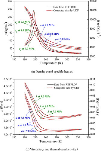
LNG is a mixture, and accordingly it is hard to know its thermal-physical properties exactly. Therefore, in this study its properties are substituted by properties of methane which is the major chemical component of LNG and has a concentration of 87.0 − 99.8% depending on the LNG sources [Citation29]. As is well known, when a fluid is at a pressure and temperature above its critical point, distinct liquid and gas phases do not exist. Therefore, the phase change phenomenon of methane no longer happens when its pressure and temperature are above 4.59 MPa and 190.56 K, respectively. The thermal-physical properties of methane, i.e., specific heat cp, density ρ, thermal conductivity λ and viscosity μ, are calculated by REFPROP at different pressures. In comparison with traditional fluid flow and heat transfer behavior, the thermal-physical properties of supercritical methane change dramatically with temperature and pressure as shown in . The temperature-dependent thermal-physical properties can be expressed by the user defined function (UDF) in ANSYS FLUENT 19.1, and deviations between the data from REFPROP and the computed data by UDF are within ±2%.
Figure 1. Thermal-physical properties of methane at different pressures.
Physical model and boundary condition
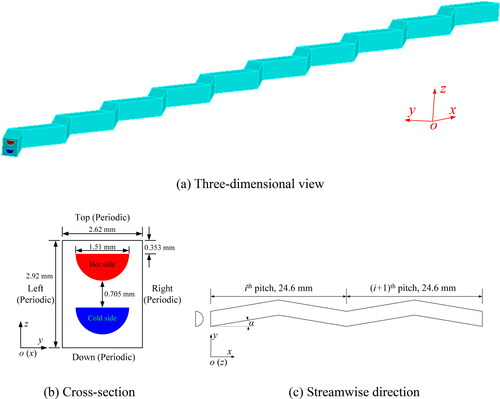
In this study, the zigzag channel PCHE studied by Kim et al. [Citation30] is selected as the physical model. The photochemical etching plates are stacked together to form the fluid flow channels, in which the cold and hot fluids flow alternately from the lower plates to the upper plates. Considering the periodic characteristics, only one couple of cold and hot channels as well as the corresponding solid plate is used for the simulation, as shown in . The top and bottom surfaces are defined as a couple of periodic boundaries, while the left and right surfaces are defined as the other couple of periodic boundaries. The supercritical LNG flow is described in a coordinate system, in which x, y, z are streamwise, spanwise, and normal coordinates, respectively. The cross-section is a semi-circle with diameter of 1.51 mm, the thickness of the plate is 1.46 mm, and the pitch of the channel in the cross-section is 2.62 mm. The shape of the channel along the streamwise direction is zigzag, whose inclination angle is 15° and pitch is 24.6 mm. There are 10 pitches along the streamwise direction so that the total length is 246 mm. In order to support a uniform velocity at the inlet and suppress the backflow at the outlet, a straight channel with length 24.6 mm is added to both the inlet and outlet regions. For the inlet boundary condition on both sides, the mass flow rate and a uniform temperature are given. At the pressure outlet boundary, the gauge pressure is defined as 0 and the backflow direction is normal to boundary, while the backflow total temperature is assumed to be equal to the inlet temperature in the opposite channel. The endwalls of the plate and outside surfaces of the extended fluid channels are assumed to be adiabatic.
Figure 2. Schematic diagram of the physical model.
Computational method
The supercritical LNG in the computational domain is regarded as three-dimensional, incompressible, laminar and quasi-steady. In the Cartesian tensor system, the governing equations including the continuity, momentum, and energy are expressed as follows
(1)
(1)
(2)
(2)
(3)
(3)
The conduction equation for the solid is described as
(4)
(4)
The corresponding equations of SST k-ω turbulence model are given as follows
(5)
(5)
(6)
(6)
where, k is the turbulent kinetic energy, ω is the specific dissipation. Gk is the turbulent kinetic energy generation by the laminar velocity gradient, Gω is the generation term in the ω equation. Гk and Гω represent the diffusivity of k and ω, respectively. Yk and Yω are terms of turbulence generation by diffusion. Dω is the orthogonal divergence term. Sk and Sω are source terms defined by the user.
The thermal conductivity of the solid wall in x-direction, y-direction and z-direction is assumed to be a constant, and there is no internal heat generation in the solid wall, therefore, EquationEq. (4)(4)
(4) can be described as
(7)
(7)
If λs,x is set as 0 in EquationEq. (7)(7)
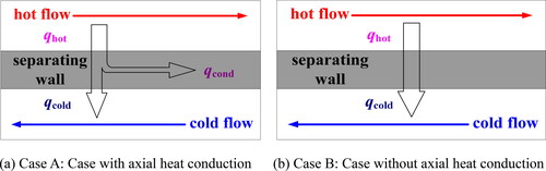
(7) , the axial heat conduction in the separating wall is negligible. Thus, the thermal performance of the case with axial heat conduction (Case A, shown in ) and that without axial heat conduction (Case B, shown in ) can be compared by setting λs,x as different values.
Figure 3. Schematic diagram of the investigated counter-flow PCHE.
The commercial software ANSYS FLUENT 19.1 is selected as the tool for the present study. The governing equations are solved by the finite control volume method. The semi-implicit method for pressure linked equations (SIMPLE) algorithm is used to deal with the coupling between pressure and velocity fields. The second-order upwind method is used to discretize the convection terms. The residuals are required to be less than 10-8 for continuity, momentum and energy equations to ensure convergence of the computations.
The local pitch-averaged heat transfer parameters in one pitch along the streamwise direction are defined as follows
(8)
(8)
(9)
(9)
(10)
(10)
in which, the thermal physical properties of LNG are evaluated at the average fluid temperature Tb in one pitch of one side. q, H, and A is the heat flux, the enthalpy, and the area in one pitch of one side, respectively. m is the mass flow rate, and Ac is the area of the cross-section in the channels. The wall temperature Tw is the area-averaged temperature along the solid-fluid interface in one pitch of one side. Dh is the hydraulic diameter and is defined by
(11)
(11)
where P is the perimeter.
The average Reynolds number and average Nusselt number are described by
(12)
(12)
(13)
(13)
Mesh generation and code validation
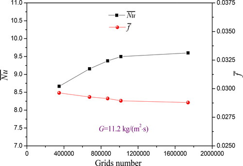
The preprocessor GAMBIT 2.4 is used to mesh the computational domain. In order to control the mesh number and improve the grid quality, a hexahedral grid is used for the meshing as shown in . Due to stringent requirements for the boundary grid density under supercritical flow and heat transfer, five boundary layers are set near the top and bottom walls, with a thickness of the first layer being 0.01 mm. In order to validate the solution independency of the grid number, five different grid systems are investigated. They are about 348800, 676400, 872100, 1014600, and 1739300. The predicted averaged Nusselt numbers and Fanning friction factor for the five grid systems are shown in . The average Nusselt number and f-factor differences between 872100 and 1014600 spaced meshes are 1.14% and 0.68%. The relative differences of average Nusselt number and f-factor with 1014600 and 1739300 spaced meshes are 1.05% and 0.54%. Hence, the 1014600 mesh element number is selected as a reference mesh size.
Figure 4. Selected grid system.
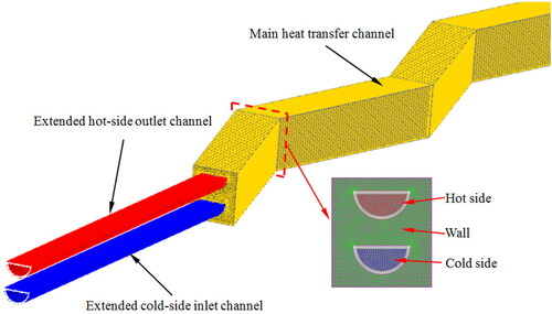
Figure 5. Variation of grid independence.
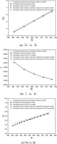
In order to validate the reliability of the numerical simulation procedure, a model set up from the experiments of Kim et al. [Citation30] was simulated with different models, i.e., laminar model with axial thermal conduction, laminar model without axial thermal conduction, SST k-ω model with axial thermal conduction, and SST k-ω model without axial thermal conduction, at the same operating conditions as in the experiments, and comparison with the experimental thermal correlation was conducted.
The thermal and hydraulic correlations including the average Nusselt number, local pitch-averaged Nusselt number, and average Fanning factor for the comparison are described as
(14)
(14)
(15)
(15)
(16)
(16)
In above correlations, the experimental Reynolds number ranged from 350 to 1200. The hot/cold side conditions were 1.5-1.9 MPa and 298-823 K/1.5-1.9 MPa and 298-373 K, respectively, and the mass flow rate ranged from 40 kg/h to 100 kg/h. The standard deviations between the experimental data and average Nusselt number correlation/average Fanning factor correlation were 0.0389 and 0.2935, respectively, and the channel averaged Nusselt number and average Fanning factor were predicted within 9.23% and 3.0% by EquationEqs. (14)(14)
(14) and Equation(16)
(16)
(16) , respectively. The cold and hot outlet temperatures calculated by EquationEq. (15)
(15)
(15) were in better agreement with the experimental data, and the averaged relative deviations were less than 1.0%.
shows the comparison between the numerical and experimental results. The numerical results for different models agree well with the experimental results. Compared with the experimental results, the averaged relative deviations of average Nusselt numbers/local pitch-averaged Nusselt number/average Fanning factor for different models (in turn laminar model with axial thermal conduction, laminar model without axial thermal conduction, SST k-ω model with axial thermal conduction, and SST k-ω model without axial thermal conduction) are −3.5%/-3.3%/-1.6%, −3.3%/-3.2%/-1.6%, −2.6%/-2.1%/-1.2%, and −2.3%/-1.8%/-1.2%, respectively. The simulation results of Case B have better agreement with the experimental results than those of Case A, in this sense, it is necessary to investigate the effect of axial heat conduction in the PCHE. The comparison results show that the difference of Nusselt numbers between the laminar model and SST k-ω model is very small, but the SST k-ω model can also be successfully applied to simulate the turbulent supercritical fluid flow [Citation20]. Therefore, the SST k-ω model is adopted in this study.
Figure 6. Numerical method validation.
Results and discussions
Effect of reynolds number on the axial heat conduction
The behavior of axial heat conduction in the separating wall in the zigzag PCHE at different Reynolds numbers is firstly investigated. summarizes the working conditions in this study, and No. 1 condition is employed in this section. The main purpose of this study is to investigate the thermal performance of the zigzag channel PCHE in a heating process, thus, the thermal performance on the cold side is discussed in detail. compares the thermal performance of Case A and Case B and shows the difference of thermal performance calculated by EquationEqs. (17)(17)
(17) and Equation(18)
(18)
(18) .
(17)
(17)
(18)
(18)
where subscript 1 represents Case B, and subscript 2 represents Case A.
Figure 7. Thermal performance comparisons versus the average Reynolds number.
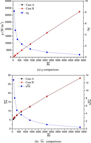
Table 1. Working conditions for different cases.
From , it is found that with the increase of average Reynolds number, the heat flux and average Nusselt number increase and the difference in thermal performance between Case A and Case B decreases. For different average Reynolds number, i.e., 90, 680, and 2650, the deviations of the heat flux and average Nusselt number between Case A and Case B are 8.2% and 12.8%, 2.3% and 3.7%, and 0.9% and 1.1%, respectively. This indicates that the axial heat conduction dominates at low Reynolds numbers and diminishes at high Reynolds numbers.
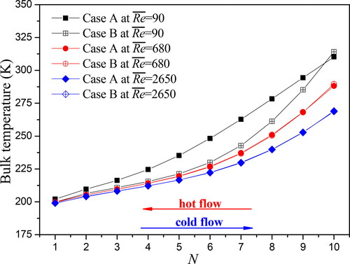
The comparisons of the wall temperature and bulk temperature for the cold side at different Reynolds numbers are shown in and . It is found that a larger wall temperature difference and bulk fluid temperature difference between Case A and Case B at low Reynolds numbers are obtained along the whole PCHE channel. With the increase of average Reynolds number, the wall temperature difference and bulk fluid temperature difference gradually decrease, and the effect of axial heat conduction can be ignored at high Reynolds numbers.
Figure 8. Wall temperature comparisons for cold side at different Reynolds numbers.
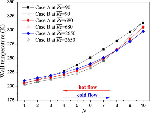
Figure 9. Bulk temperature comparisons for cold side at different Reynolds numbers.
Effect of operating pressure on the axial heat conduction
The thermal performance of PCHEs is greatly affected by the operational parameters, such as the operating pressure and inlet temperature. The numerical simulations are conducted at predetermined operating pressures to study the axial heat conduction of the zigzag channel PCHE in this section. The working condition for numerical simulations in this section is No. 2 condition listed in .
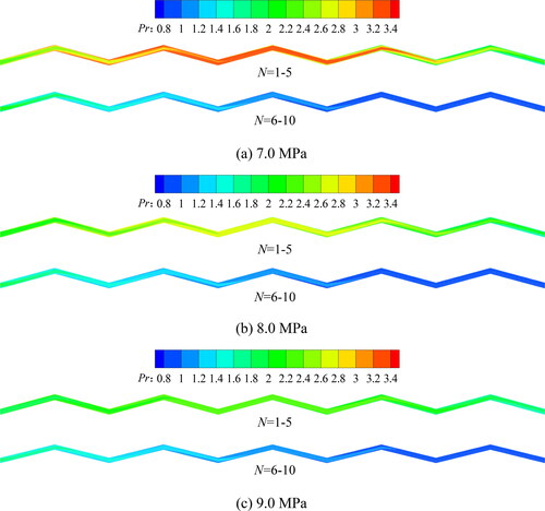
In a PCHE cold-side channel, the temperature of supercritical LNG gradually increases in a heating process and the thermal-physical properties undergo dramatic changes. The Prandtl number (Pr) at the central cross-section of the cold side in the z-direction of the PCHE along the main flow direction at G = 5.6 kg/(m2·s) is shown in . It can be seen that the Prandtl number increases first and then decreases along the main flow direction at different operating pressures.
Figure 10 Pr at the central cross-section of the cold side in the z-direction at G = 5.6 kg/(m2·s).
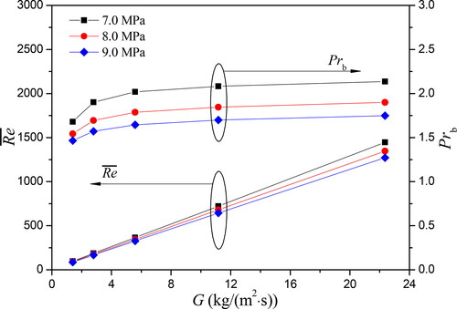
The thermal performance of the zigzag channel PCHE is compared at different operating pressures in , where the mass flux in the channel is taken as the abscissa. It is found that the average Nusselt number increases with the increase of mass flux and decreases as the pressure increases. This can be explained as follows. The viscosity of supercritical LNG in the channel is smaller at a lower pressure as shown in , thus, the Reynolds number at the lower pressure is larger at the same mass flux in . In addition, it can be also seen from that the Prandtl number of supercritical LNG decreases with the increase of operating pressure. It is well known that the Nusselt number increases with the increase of Reynolds number and Prandtl number, as a consequence of the above two main reasons, the thermal performance of the zigzag channel PCHE becomes better as pressure decreases.
Figure 11. Thermal performance comparisons at different pressures.
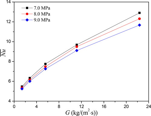
Figure 12. and Prb comparisons at different pressures.
The effects of operating pressure on the thermal performance of Case A and Case B are shown in . From , it is found that with the increase of mass flux, the average Nusselt number of Case B increases and the difference of thermal performance between Case A and Case B decreases. For different operating pressure, i.e., 7.0 MPa, 8.0 MPa, and 9.0 MPa, the deviations of the average Nusselt number between Case A and Case B are 13.8%, 12.8% and 12.2% at G = 1.4 kg/(m2·s), 4.9%, 4.7% and 4.6% at G = 5.6 kg/(m2·s), and 2.4%, 2.3% and 2.1% at G = 22.4 kg/(m2·s), respectively. This can also indicate that the axial heat conduction can greatly affect the thermal performance of the PCHE at low mass flux and decrease at high mass flux.
Figure 13. Thermal performance comparisons at different operating pressures.
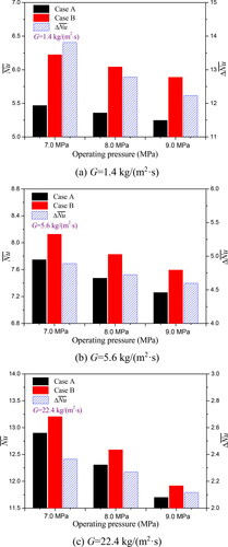
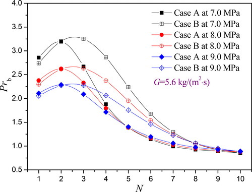
compares the average Prandtl number of each row in the zigzag channel PCHE for different operating pressures at G = 5.6 kg/(m2·s). It can be seen that the Prandtl number increases first and then decreases along the main flow direction, and the Prandtl number of Case B is higher than that of Case A at the same mass flux. Based on the simulation results, the average Prandtl numbers of Case A in the zigzag channel PCHE for operating pressures of 8.0 MPa and 9.0 MPa are reduced by 11.5% and 18.6%, respectively, and the average Prandtl numbers of Case B for operating pressures of 8.0 MPa and 9.0 MPa are reduced by 12.1% and 19.5%, respectively, compared with the operating pressure of 7.0 MPa. Therefore, the effect of operating pressure on the average Prandtl number of Case B is larger than that of Case A, and this can explain why the difference of thermal performance between Case A and Case B decreases with the increase of operating pressure.
Figure 14. Prb comparisons in each row at G = 5.6 kg/(m2·s).
Effect of inlet temperature of the cold side on the axial heat conduction
The inlet temperature can also affect the thermal performance of the PCHE, and the effect of inlet temperature on axial heat conduction of the zigzag channel PCHE is studied in this section. The working condition is No. 3 condition listed in .
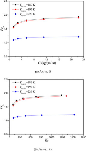
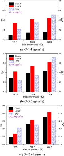
The thermal performance of the zigzag channel PCHE is compared at different inlet temperatures of the cold side in , where the mass flux and average Reynolds number in the channel is taken as the abscissa in a) and b), respectively. In , it can be seen that the average Nusselt number increases with the increase of mass flux and average Reynolds number, and the Reynolds number at a lower inlet temperature is smaller at the same mass flux. The thermal performance increases with the increase of the inlet temperature of the cold side at the same mass flux as shown in . compares the average Prandtl number of supercritical LNG in the zigzag channel PCHE at different inlet temperatures of the cold side, and it can be seen that the Prandtl number decreases with the increase of the inlet temperature of the cold side. As is well known, not only large Reynolds number but also large Prandtl number can improve the thermal performance of heat exchangers, and a larger Reynolds number plays the dominant role inducing better thermal performance. Therefore, the inlet temperature of 220 K offers the best thermal performance among the three different inlet temperatures of the cold side at the same mass flux. While from , it is indicated that under the same average Reynolds number, the thermal performance at the inlet temperature of 195 K is the best and the inlet temperature of 220 K provides the worst thermal performance among the three different inlet temperatures of the cold side. This is because the specific heat of supercritical methane is like a pulse function near the pseudo-critical point which is about 210.1 K at 8.0 MPa in , and the zigzag channel PCHE can make full use of the advantage of the larger specific heat to enhance heat transfer at the same average Reynolds number when the temperature of supercritical methane along the flow direction in the PCHE channel passes through the pseudo-critical temperature.
Figure 15. Thermal performance comparisons at different inlet temperatures.
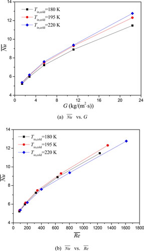
Figure 16. Prb comparisons at different inlet temperatures.
The effect of the inlet temperature of the cold side on the thermal performance of Case A and Case B is shown in . From , it can be seen that with the increase of the inlet temperature of the cold side, the average Nusselt number of Case B and the difference of thermal performance between Case A and Case B increases at the same mass flux, and the effect of the inlet temperature of the cold side on axial heat conduction is larger at low mass flux and becomes smaller at high mass flux.
Figure 17. Thermal performance comparisons at different inlet temperatures.
Effect of wall thermal conductivity on the axial heat conduction
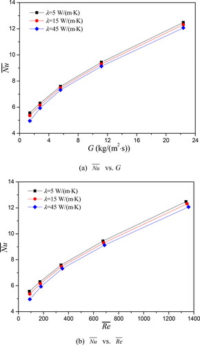
It is well known that the wall thermal conductivity is a physical parameter that affects axial heat conduction, and attention is now turned to the effect of the wall thermal conductivity in this section. The working condition for numerical simulations is No. 4 condition listed in . The effect of wall thermal conductivity on the thermal performance of the zigzag channel PCHE is compared in , where the mass flux and average Reynolds number in the channel is taken as the abscissa in a) and b), respectively. In , it can be seen that the average Nusselt number increases with the increase of mass flux and average Reynolds number, and the average Nusselt number decreases as the wall thermal conductivity increases. The reason can be explained as follows. Although an increase in the thermal conductivity of solid material leads to a decrease of thermal resistance which can increase the heat flux transferred from hot fluid to cold fluid, but the axial heat conduction flux into the separating wall increases with increasing the wall thermal conductivity, the overall effect of above two influence factors results in the decrease of heat flux as shown in . It can also be seen that the average Prandtl number of hot fluid is smaller at a larger wall thermal conductivity from . Since the Nusselt number increases with the increase of Prandtl number, the thermal performance becomes better as the wall thermal conductivity decreases in the range of the studied mass flux.
Figure 18. Thermal performance comparisons for different wall thermal conductivity.
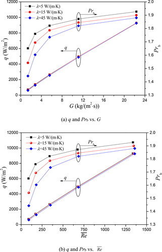
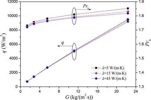
The comparison of heat flux and average Prandtl number in the zigzag channel PCHE for different wall thermal conductivity is shown in , and it is found that the heat flux and average Prandtl number decrease with the increase of wall thermal conductivity at the same mass flux or at the same average Reynolds number. Based on the numerical results, compared with the case of wall thermal conductivity of 45 W/(m·K), the heat flux with wall thermal conductivity of 5 W/(m·K) and 15 W/(m·K) increases by 16.7% and 11.6% at G = 1.4 kg/(m2·s), 4.0% and 3.2% at G = 5.6 kg/(m2·s), and 0.4% and 0.3% at G = 22.4 kg/(m2·s), respectively, and the average Prandtl number with wall thermal conductivity of 5 W/(m·K) and 15 W/(m·K) increases by 14.4% and 6.8% at G = 1.4 kg/(m2·s), 5.0% and 3.0% at G = 5.6 kg/(m2·s), and 2.5% and 1.0% at G = 22.4 kg/(m2·s), respectively. The comparative results indicate that the reduction of the wall thermal conductivity can improve the thermal performance of the PCHE due to the influence of axial heat conduction in the separating wall. However, it is worth to point out that the thermal performance can be improved by reducing the wall thermal conductivity at low mass flux, and reducing the wall thermal conductivity provides a minor benefit at high mass flux.
Figure 19. q and Prb comparisons for different wall thermal conductivity.
The effect of wall thermal conductivity on the thermal performance of Case A and Case B is shown in . In , the average Nusselt number of Case B increases and the difference of thermal performance between Case A and Case B decreases with the increase of mass flux, and it can be deduced that the effect of wall thermal conductivity on the thermal performance of the PCHE can be ignored at high mass flux. shows the comparisons of q and Prb for Case B at different wall thermal conductivity. It can be seen that the heat flux increases with the increase of wall thermal conductivity, while the average Prandtl number decreases as the wall thermal conductivity increases. Under these conditions, the effect of increasing Prandtl number plays the dominant part to increase the Nusselt number, so the Nusselt number is also larger at a smaller wall thermal conductivity, but the relative deviations of Nusselt numbers become smaller than those of Case A as shown in .
Figure 20. Thermal performance comparisons for different wall thermal conductivity.
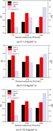
Figure 21. q and Prb of Case B comparisons for different wall thermal conductivity.
Conclusions
The effect of axial heat conduction on the thermal performance in a zigzag channel PCHE under different conditions was studied by a numerical method. The main conclusions can be summarized as follows:
The heat flux and average Nusselt number increase and the difference of thermal performance between Case A and Case B decreases with the increase of average Reynolds number, and the axial heat conduction dominates at low Reynolds numbers and diminishes at high Reynolds numbers.
The thermal performance increases with the increase of mass flux and decreases as the pressure increases. The axial heat conduction can greatly affect the thermal performance of the PCHE at low Reynolds numbers but decrease it at high Reynolds numbers.
Moreover, the comparative results indicate that at the same average Reynolds number, the thermal performance at an inlet temperature of 195 K is the best and the inlet temperature of 220 K provides the worst thermal performance among the three different inlet temperatures of the cold side. It is also found that with the increase of mass flux, the average Nusselt number of Case B increases and the difference of thermal performance between Case A and Case B decreases for different inlet temperatures of the cold side.
Finally, the effect of wall thermal conductivity on the thermal performance of the zigzag channel PCHE is compared. The comparative results indicate that the reduction of wall thermal conductivity can improve the thermal performance of the PCHE due to the influence of axial heat conduction in the separation wall, but it is worth to point out that the thermal performance can be improved by reducing the wall thermal conductivity at low mass flux, and reducing the wall thermal conductivity produces a minor benefit at high mass flux.
| Nomenclature | ||
| A | = | area, m2 |
| Ac | = | area of cross-section in the channel, m2 |
| cp | = | specific heat at constant pressure, J/(kg·K) |
| Dh | = | hydraulic diameter, mm |
| Dω | = | orthogonal divergence term, kg/(m3·s2) |
| = | average Fanning factor in the channel | |
| h | = | heat transfer coefficient, W/(m2·K) |
| H | = | enthalpy, J/kg |
| G | = | mass flux, kg/(m2·s) |
| Gk | = | generation of turbulence kinetic energy, kg/(m·s3) |
| Gω | = | generation term in the ω equation, kg/(m3·s2) |
| k | = | kinetic energy, m2/s2 |
| LNG | = | liquefied natural gas |
| LNG- FPSO | = | liquefied natural gas - floating production storage and offloading |
| m | = | mass flow rate, kg/s |
| N | = | pitch number |
| NG | = | natural gas |
| Nu | = | local pitch-averaged Nusselt number |
| = | averaged Nusselt number in the channel | |
| p | = | pressure, Pa |
| P | = | perimeter, mm |
| PCHE | = | printed circuit heat exchanger |
| Pr | = | Prandtl number |
| q | = | heat flux, W/m2 |
| Re | = | local pitch-averaged Reynolds number |
| = | averaged Reynolds number in the channel | |
| SIMPLE | = | semi-implicit method for pressure-linked equations |
| Sk | = | source term in the k equation, kg/(m·s3) |
| Sω | = | source term in the ω equation, kg/(m3·s2) |
| SST | = | shear stress transport |
| T | = | temperature, K |
| u | = | velocity, m/s |
| UDF | = | user defined function |
| x, y, z | = | Cartesian coordinates |
| Yk | = | dissipation of k, kg/(m·s3) |
| Yω | = | dissipation of ω, kg/(m3·s2) |
| Greek symbols | ||
| α | = | inclined angle, ° |
| Гk | = | diffusion coefficient of k, kg/(m·s) |
| Гω | = | diffusion coefficient of ω, kg/(m·s) |
| δij | = | Kronecker delta |
| = | difference of averaged Nusselt number | |
| Δq | = | difference of heat flux |
| λ | = | thermal conductivity, W/(m·K) |
| μ | = | dynamic viscosity, kg/(m·s) |
| ρ | = | density, kg/m3 |
| = | internal heat generation, W/m3 | |
| ω | = | specific dissipation rate, 1/s |
| Subscripts | ||
| 1 | = | case B without axial heat conduction |
| 2 | = | case A with axial heat conduction |
| b | = | average value |
| cold | = | cold side |
| cond | = | conduction |
| f | = | fluid |
| hot | = | hot side |
| in | = | inlet |
| i, j, k | = | tensor index symbols (i or j or k = 1, 2, 3 in Cartesian coordinate) |
| out | = | outlet |
| s | = | solid |
| w | = | wall |
Additional information
Funding
Notes on contributors

Ling-Hong Tang
Linghong Tang is a visiting scholar at the Department of Energy Sciences of Lund University. He is an associate professor in the School of Mechanical Engineering, Xi’an Shiyou University. He received his Ph.D. degree in engineering thermophysics from Xi’an Jiaotong University in 2009, and he finished his postdoctoral research from Harbin Engineering University in 2014. His main research interests are numerical heat transfer and compact heat exchangers.

Bo-Hao Yang
Bohao Yang is a master student in the School of Mechanical Engineering, Xi’an Shiyou University. He received his bachelor degree in power engineering and engineering thermophysics from Henan University of Science and Technology in 2018. Now he studies the thermal and hydraulic performance of PCHEs.

Jie Pan
Jie Pan is an associate professor at the Department of Oil and Gas Storage and Transportation Engineering of Xi’an Shiyou University. His major research fields are multiphase flow in petroleum engineering, LNG heat exchanger and LNG cold energy utilization.

Bengt Sundén
Bengt Sundén received his M.Sc. in Mechanical Engineering 1973, Ph.D. in Applied Thermodynamics and Fluid Mechanics 1979, became Docent in Applied Thermodynamics and Fluid Mechanics 1980, all at Chalmers University of Technology, Göteborg, Sweden. He is a professor of Heat Transfer, Lund University, and he serves as Professor Emeritus and Senior Professor in Heat Transfer since 2016-10-01. He is a fellow of the ASME. The research activities cover compact heat exchangers, heat transfer enhancement, gas turbine heat transfer, combustion-related heat transfer including thermal radiation, CFD-methods, liquid crystal thermography, condensation and evaporation on micro-nanostructured surfaces, nanofluids, impinging jets, aerospace heat transfer, computational modeling and analysis of multiphysics and multiscale phenomena for fuel cells (SOFC, SOEC, PEMFC), and thermal management of batteries.
References
- V. Smil, Natural Gas: Fuel for the 21st Century, United Kingdom: John Wiley & Sons, 2015.
- D. Popov, et al., “Cryogenic heat exchangers for process cooling and renewable energy storage: A review,” Appl. Therm. Eng., vol. 153, pp. 275–290, Feb. 2019. DOI: https://doi.org/10.1016/j.applthermaleng.2019.02.106.
- W. Won, S. K. Lee, K. Choi and Y. Kwon, “Current trends for the floating liquefied natural gas (FLNG) technologies,” Korean J. Chem. Eng., vol. 31, no. 5, pp. 732–743, Mar. 2014. DOI: https://doi.org/10.1007/s11814-014-0047-x.
- S. Baek, G. Hwang, S. Jeong and J. Kim, “Development of compact heat exchanger for LNG FPSO,” Presented at the Twenty-First International Offshore and Polar Engineering Conference, 2011. Maui, Hawaii, USA, Jun. 19-24,
- Y. L. Fan and L. G. Luo, “Recent applications of advances in microchannel heat exchangers and multi-scale design optimization,” Heat Transf. Eng., vol. 29, no. 5, pp. 461–474, 2008. DOI: https://doi.org/10.1080/01457630701850968.
- F. Xin, T. Ma, Y. T. Chen and Q. W. Wang, “Two-Dimensional chemical etching process simulation for printed circuit heat exchanger channels based on cellular automata model,” Heat Transf. Eng., vol. 39, no. 7-8, pp. 617–629, 2018. 1325660. DOI: https://doi.org/10.1080/01457632.2017.
- D. Reay, C. Ramshaw and A. Harvey, Process Intensification: Engineering for Efficiency, Sustainability and Flexibility, United Kingdom: Butterworth-Heinemann, 2013
- S. K. Mylavarapu, X. Sun, R. E. Glosup, R. N. Christensen and M. W. Patterson, “Thermal hydraulic performance testing of printed circuit heat exchangers in a high-temperature helium test facility,” Appl. Therm. Eng, vol. 65, no. 1-2, pp. 605–614, Jan. 2014. DOI: https://doi.org/10.1016/j.applthermaleng.2014.01.025.
- A. M. Aneesh, A. Sharma, A. Srivastava, K. N. Vyas, and P. Chaudhuri, “Thermal-hydraulic characteristics and performance of 3D straight channel based printed circuit heat exchanger,” Appl. Therm. Eng., vol. 98, pp. 474–482, Dec. 2016. DOI: https://doi.org/10.1016/j.applthermaleng.2015.12.046..
- W. X. Chu, X. Li, T. Ma, Y. T. Chen and Q. W. Wang, “Experimental investigation on SCO2-water heat transfer characteristics in a printed circuit heat exchanger with straight channels,” Int. J. Heat Mass Transf., vol. 113, pp. 184–194, Oct. 2017. DOI: https://doi.org/10.1016/j.ijheatmasstransfer.2017.05.059..
- S. M. Lee and K. Y. Kim, “A parametric study of the thermal-hydraulic performance of a zigzag printed circuit heat exchanger,” Heat Transf. Eng., vol. 35, no. 13, pp. 1192–1200, 2014. DOI: https://doi.org/10.1080/01457632.2013.870004.
- T. Ma, L. Li, X. Y. Xu, Y. T. Chen and Q. W. Wang, “Study on local thermal-hydraulic performance and optimization of zigzag-type printed circuit heat exchanger at high temperature,” Energy Convers. Manag., vol. 104, pp. 55–66, Mar. 2015. DOI: https://doi.org/10.1016/j.enconman.2015.03.016..
- W. X. Chu, X. H. Li, Y. T. Chen, Q. W. Wang and T. Ma, “Experimental study on small scale printed circuit heat exchanger with zigzag channels,” Heat Transf. Eng., vol. 42, no. 9, 2021. (in press). DOI: https://doi.org/10.1080/01457632.2020.1735779..
- Y. J. Baik, S. Jeon, B. Kim, D. Jeon and C. Byon, “Heat transfer performance of wavy-channeled PCHEs and the effects of waviness factors,” Int. J. Heat Mass Transf., vol. 114, pp. 809–815, Jul. 2017. DOI: https://doi.org/10.1016/j.ijheatmasstransfer.2017.06.119.
- A. M. Aneesh, A. Sharma, A. Srivastava, and P. Chaudhury “Effects of wavy channel configurations on thermal-hydraulic characteristics of Printed Circuit Heat Exchanger (PCHE),” Int. J. Heat Mass Transf, vol. 118, pp. 304–343, Feb. 2018. DOI: https://doi.org/10.1016/j.ijheatmasstransfer.2019.01.044.
- Y. Yang, et al., “Investigation on the effects of narrowed channel cross-sections on the heat transfer performance of a wavy-channeled PCHE,” Int. J. Heat Mass Transf., vol. 135, pp. 33–43, Feb. 2019.
- T. L. Ngo, Y. Kato, K. Nikitin and N. Tsuzuki, “New printed circuit heat exchanger with S-shaped fins for hot water supplier,” Exp. Therm. Fluid Sci, vol. 30, no. 8, pp. 811–819, 2006. DOI: https://doi.org/10.1016/j.expthermflusci.2006.03.010.
- N. Tsuzuki, Y. Kato and T. Ishiduka, “High performance printed circuit heat exchanger,” Appl. Therm. Eng., vol. 27, no. 10, pp. 1702–1707, 2007. 2006. 07.007. DOI: https://doi.org/10.1016/j.applthermaleng.
- W. X. Chu, K. Bennett, J. Cheng, Y. T. Chen and Q. W. Wang, “Thermo-hydraulic performance of printed circuit heat exchanger with different cambered airfoil fins,” Heat Transf. Eng., vol. 41, no. 8, pp. 708–722, 2020. DOI: https://doi.org/10.1080/01457632.2018.1564203.
- L. H. Tang, J. Pan and B. Sundén, “Investigation on thermal-hydraulic performance in a printed circuit heat exchanger with airfoil and vortex generator fins for supercritical liquefied natural gas,” Heat Transf. Eng., vol. 42, no. 10, 2021. (in press). DOI: https://doi.org/10.1080/01457632.2020.1744244.
- L. H. Tang, L. Cui and B. Sundén, “Optimization of fin configurations and layouts in a printed circuit heat exchanger for supercritical liquefied natural gas near the pseudo-critical temperature,” Appl. Therm. Eng., vol. 172, pp. 115131, 2020. DOI: https://doi.org/10.1016/j.applthermaleng.2020.115131.
- M. H. Chen, et al., “Pressure drop and heat transfer characteristics of a high-temperature printed circuit heat exchanger,” Appl. Therm. Eng., vol. 108, pp. 1409–1417, Sep. 2016. DOI: https://doi.org/10.1016/j.applthermaleng.2016.07.149.
- S. Y. Lee, B. G. Park and J. T. Chung, “Numerical studies on thermal hydraulic performance of zigzag-type printed circuit heat exchanger with inserted straight channels,” Appl. Therm. Eng., vol. 123, pp. 1434–1443, Jun. 2017. DOI: https://doi.org/10.1016/j.applthermaleng.2017.05.198..
- H. Y. Zhang, J. F. Guo, X. L. Huai, K. Y. Chen and X. Y. Cui, “Studies on the thermal-hydraulic performance of zigzag channel with supercritical pressure CO2J,” Supercrit. Fluid,” vol. 148, pp. 104–115, Mar. 2019. DOI: https://doi.org/10.1016/j.supflu.2019.03.003.
- S. Baek, J. H. Kim, S. Jeong and J. Jung, “Development of highly effective cryogenic printed circuit heat exchanger (PCHE) with low axial conduction,” Cryogenic, vol. 52, no. 7-9, pp. 366–374, Mar. 2012. DOI: https://doi.org/10.1016/j.cryogenics.2012.03.001.
- G. F. Nellis, “A heat exchanger model that includes axial conduction, parasitic heat loads, and property variations,” Cryogenic, vol. 43, no. 9, pp. 523–538, Jun. 2003. DOI: https://doi.org/10.1016/S0011-2275(03)00132-2..
- L. Zhai, et al., “Numerical analysis of the axial heat conduction with variable fluid properties in a forced laminar flow tube,” Int. J. Heat Mass Transf., vol. 114, pp. 238–251, Jun. 2017. DOI: https://doi.org/10.1016/j.ijheatmasstransfer.2017.06.041.
- M. Vera and A. E. Quintero, “On the role of axial wall conduction in mini/micro counterflow heat exchangers,” Int. J. Heat Mass Transf., vol. 116, pp. 840–857, Sep. 2018. DOI: https://doi.org/10.1016/.j.ijheatmasstransfer.2017.09.055.
- S. Mokhatab, J. Y. Mak, J. V. Valappil and D. A. Wood, Handbook of Liquefied Natural Gas, Burlington, Canada: Gulf Professional Publishing, 2013.
- I. H. Kim, H. C. No, J. I. Lee and Y. G. Jeon, “Thermal hydraulic performance analysis of the printed circuit heat exchanger using a helium test facility and CFD simulations,” Nucl. Eng. Des, vol. 239, no. 11, pp. 2399–2408, Jul. 2009. DOI: https://doi.org/10.1016/j.nucengdes.2009.07.005.