
 ?Mathematical formulae have been encoded as MathML and are displayed in this HTML version using MathJax in order to improve their display. Uncheck the box to turn MathJax off. This feature requires Javascript. Click on a formula to zoom.
Abstract
Compact recuperative heat exchangers are critical components in supercritical carbon dioxide (sCO2) waste heat to power conversion systems. To investigate their thermohydraulic performance, a model based on the segmental design and the ε-NTU method has been developed. Four different types of heat exchanger have been considered: printed circuit heat exchanger with straight channels (PCHE-SC); printed circuit heat exchanger with zigzag channels (PCHE-ZC); microtube heat exchanger (MTHE); and microtube heat exchanger with separator sheets (MTHE-SS). The performance of the heat exchangers for different fluid mass flow rates, temperatures, and lengths was investigated in terms of Nusselt number, heat transfer coefficient, friction factor, pressure drop, heat transfer rate, entropy generation rate, and augmentation entropy generation number. Results show that these parameters significantly impact on the thermohydraulic performance of compact recuperative heat exchangers and their optimal design. For the same operating conditions and equal heat transfer rate, PCHE-ZC and MTHE-SS can have a significantly smaller size than PCHE-SC and MTHE. The augmentation entropy generation number also demonstrates the improved performance and compactness that can arise from zigzag channels and separator sheets, making them suitable for demanding high pressure and temperature applications such as sCO2 heat to power conversion systems.
Introduction
Supercritical carbon dioxide (sCO2) has been attracting increasing attention in waste heat to power conversion applications due to its environmental credentials and many advantages over conventional power cycles. Compared to the conventional steam Rankine cycle, the Brayton cycle using sCO2 as the working fluid can offer a greater power density and reduced compressive work, compact size, and potential for lower capital cost. Potential applications include fossil fuel plants, nuclear, waste heat recovery, and concentrated solar energy power generation [Citation1–3]. For sCO2 waste heat to power conversion systems, the recuperative heat exchanger transfers heat from the turbine outlet to the compressor outlet enabling reduction in the heat input and higher temperatures at the turbine that lead to higher cycle efficiency [Citation4]. Considering the operating conditions of sCO2 power systems, the requirements to transfer high thermal duty and operate at high pressure, high-temperature and high-pressure differentials between the exchanging fluids, necessitate the recuperative heat exchangers to offer high heat transfer capacity, compact construction, high pressure capability, and wide range of operating temperatures. Furthermore, taking material selection and thermohydraulic performance into account, the compact high nickel alloy heat exchangers are good choices for sCO2 power cycles due to their large heat transfer surface area per unit volume, low fluid inventory, and ability to withstand high operating pressures and temperatures [Citation1, Citation5].
For compact recuperative heat exchangers used in sCO2 power cycles, very few researches focus on the test facilities and experimental work. The Sandia National Laboratory and the Knolls Atomic Power Laboratory in the USA and the Institute of Applied Energy in Japan are amongst the first to build small scale sCO2 Brayton cycle power systems, and undertake testing on the thermomechanical and thermohydraulic performance of sCO2 recuperative heat exchangers [Citation6–8]. In these test facilities, the Heatric printed circuit heat exchanger (PCHE) was employed to achieve high effectiveness values [Citation9]. Nikitin et al. [Citation10] and Ngo et al. [Citation11] tested the thermohydraulic performance of PCHEs with S-shaped fins and zigzag channels. Both PCHEs were found to have superior heat transfer performance than either plate fin or circular tube heat exchangers. The PCHE with zigzag channels showed 24–34% larger Nusselt number but 4–5 times higher pressure drops than that with the S-shaped fins. Chu et al. [Citation12] investigated the thermohydraulic performance of PCHEs with different zigzag angles. The PCHE with zigzag angle 25° showed the best thermohydraulic performance with fourfold Nusselt numbers and double average friction factors of that with straight channels. Fourspring et al. [Citation13] examined two compact recuperative heat exchangers, one utilizing wire meshes and the other folded wavy fins as the extended heat transfer surface. The compact heat exchangers employing the folded wavy fins performed well, achieving the design heat transfer rate with less than half the allowable pressure drop. Chordia et al. [Citation14] built and tested the microtube heat exchangers for sCO2 recuperators with promising results for heat transfer and pressure drop.
Three-dimensional computational fluid dynamics (CFD) modeling has been performed by a number of researchers to investigate the heat transfer and pressure drop characteristics of PCHEs with straight and zigzag channels. Chai and Tassou [Citation15] investigated the thermohydraulic performance of sCO2 flow in a PCHE with straight channels and compared the local heat transfer and friction pressure drop results with predictions from empirical correlations. Kim et al. [Citation16], Lee and Kim [Citation17, Citation18], Kim et al. [Citation19], Lee et al. [Citation20], and Meshram et al. [Citation21] investigated the thermohydraulic performance of PCHEs with zigzag channels. The zigzag channels offer superior heat transfer enhancement compared to the straight channels but at the expense of higher pressure drop. However, the three-dimensional CFD modeling requires much longer computational time due to the large number of elements involved in the computational grid [Citation22], leading to the one-dimensional segmental approach is preferable for the transient simulations and complex optimization studies of sCO2 recuperators. Guo [Citation23] and Guo and Huai [Citation24] demonstrated the modeling of recuperative heat exchangers with the segmental approach and the ε-NTU method and performed the thermohydraulic performance to inform the selection of PCHE with straight channels. Jiang et al. [Citation25] and Marchionni et al. [Citation22] built one-dimensional dynamic models for the optimal design of PCHEs with zigzag channels in the sCO2 power cycle. provides a brief summary of these studies.
Table 1. Representative studies of sCO2 recuperative heat exchangers.
From the literature survey, compact recuperative heat exchangers used in sCO2 power cycles are primarily PCHEs but suffer from relatively high cost [Citation2]. Fleming et al. [Citation26] suggested that the use of a lower efficiency and less costly heat exchanger may make sCO2 technology more attractive for commercialization. Chordia et al. [Citation14] recommended the use of microtube heat exchangers as recuperators due to their potential to satisfy the high temperature and high differential pressure criteria but at much lower capital costs than PCHEs.
This article makes contributions to the literature on the selection and design of recuperative heat exchangers for sCO2 cycle applications by considering the characteristics of four alternative designs: printed circuit heat exchanger with straight channels (PCHE-SC); printed circuit heat exchanger with zigzag channels (PCHE-ZC); microtube heat exchanger (MTHE); and microtube heat exchanger with separator sheets (MTHE-SS). The analysis was based on the segmental modeling approach and the ε-NTU method considering heat transfer, pressure drop, and compactness of the heat exchanger as the primary criteria for sCO2 waste heat to power conversion system applications.
Geometry of selected compact recuperative heat exchangers
illustrates the four different types of compact recuperative heat exchangers: PCHE-SC, PCHE-ZC, MTHE, and MTHE-SS. In these figures, the cold and hot sCO2 regions are, respectively, colored blue and red, and the region of stainless steel is shown in gray.
Figure 1. Three-dimensional diagram of compact recuperative heat exchangers (a) PCHE-SC, (b) PCHE-ZC, (c) MTHE, and (d) MTHE-SS.
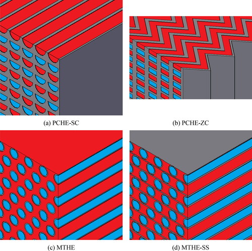
The parameters of the PCHE-SC and PCHE-ZC are from Mylavarapu et al. [Citation27] and Ngo et al. [Citation11], respectively. For both heat exchangers, the channel geometries on the hot and cold sides are the same. For the PCHE-SC, the plate thickness is 1.63 mm, the horizontal channel pitch 2.5 mm, and the diameter of the semi-circular channel is 2 mm. For the PCHE-ZC, the plate thickness is 1.5 mm, the longitudinal and horizontal fin pitches are 7.565 mm and 3.426 mm, respectively, the fin angle to the longitudinal direction is 52°, and the fin width, depth, and gap, 0.8, 0.94, and 1.31 mm, respectively.
Microtube bundles can have high heat transfer efficiency and accommodate high thermal stresses. Axial separation sheets can direct the flow in a strictly counter-current direction and can also be used as extended heat transfer surface [Citation14]. For the MTHE, the cold CO2 flows inside and the hot CO2 outside the microtubes. In the microtube column, the horizontal tube pitch is 2 mm, the vertical pitch 1.3 mm, the internal tube diameter 1.0 mm and the tube thickness 0.1 mm.
For the MTHE-SS, the cold sCO2 flows inside of microtubes and the hot sCO2 flows through the channels formed by the microtubes and the separator sheets. The diameter and thickness of the microtubes are the same as those of the MTHE. The thickness of the horizontal separator sheets is 0.1 mm.
Model development
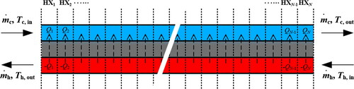
The segmental approach and the ε-NTU method have been employed in the modeling of the compact recuperative heat exchangers. demonstrates the segment design with counter flow for the studied heat exchangers. As N > 80, the change of both heat transfer and pressure drop is less than 1% for all the investigated cases in the present study. Considering data reduction, each heat exchanger was divided into N = 100 segments along the sCO2 flow direction. The following assumptions have been made for the cold and the hot sides: steady state model; counter flow; one-dimensional homogeneous flow; the thermophysical properties in each segment are constant and from the NIST REFPROP v9.1 database (National Institute of Standards and Technology, Gaithersburg, Maryland, United States); mass flow rate on the cold and hot sides is balanced; axial heat conduction is neglected; radiation heat transfer is neglected; heat exchanger material is stainless steel and its thermal conductivity is 16.2 W/(m K).
Figure 2. Schematic of heat exchanger segment.
Using the above assumptions and energy balance, the ε-NTU method is employed to calculate the heat transfer rate in each segment. For a given segment i,
(1)
(1)
where Q is the heat transfer rate, ε is the heat exchanger effectiveness, C is the capacity rate, Th and Tc are the sCO2 temperatures on the hot and cold sides, respectively.
(2)
(2)
where NTU is the number of transfer units,
(3)
(3)
(4)
(4)
(5)
(5)
(6)
(6)
where U is the overall heat transfer coefficient,
(7)
(7)
The cold side heat transfer coefficient hc, i and friction factor fc, i for PCHE-SC, MTHE, and MTHE-SS are computed using the Gnielinski equation [Citation28],
(8)
(8)
(9)
(9)
These correlations are applicable to 2300 < Rec, i < 106, 0.5 < Prc, i < 2000.
The hc, i and fc, i for PCHE-ZC are calculated using the correlation of Ngo et al. [Citation11],
(10)
(10)
(11)
(11)
where Rec, i and D are defined as:
(12)
(12)
(13)
(13)
where G is the mass flux, A is the cross-sectional area of the flow, and P is the wetted perimeter of the cross section. EquationEquations (10)
(10)
(10) and Equation(11)
(11)
(11) were proposed based on the sCO2 data base of 3.5 × 10³ < Rec, i < 2.2 × 10⁴ and 0.75 < Prc, i < 2.2. Kim et al. [Citation19] further validated them covering an extended Reynolds number range of 3.5 × 10³ < Rec, i < 5.8 × 10⁴.
The hot side heat transfer coefficient hh, i and friction factor fh, i for PCHE-SC, MTHE, and MTHE-SS are determined from the Gnielinski equation [Citation28],
(14)
(14)
(15)
(15)
The hh, i and fh, i for PCHE-ZC are gained from the correlation of Ngo et al. [Citation11],
(16)
(16)
(17)
(17)
The Reh, i is defined as
(18)
(18)
where D is the hydraulic diameter and calculated from EquationEquation (13)
(13)
(13) .
Correlations (8), (9), (14), and (15) used for straight channels have been validated by Chai and Tassou [Citation15] against results from CFD simulations. These correlations have also been employed by Guo [Citation23] and Guo and Huai [Citation24] for sCO2 recuperative heat exchanger design. Correlations (10), (11), (16), and (17) used for zigzag channels are those published by Ngo et al. [Citation11] which were developed from experimental test results.
The efficiency of a single fin ηf for calculation of the thermal resistance of the separator sheets in the MTHE-SS heat exchanger is defined as:
(19)
(19)
(20)
(20)
where H is the half height of the fin considering symmetry, δ is the fin thickness.
The pressure drops Δpc, i and Δph, i considering flow acceleration on the cold side and flow deceleration on the hot side, are calculated as:
(21)
(21)
(22)
(22)
The flow chart of the modeling procedure is shown in . The output parameters of the modeling for average thermohydraulic performance, such as Reynold number, Nusselt number, friction factor, heat transfer coefficient, pressure drop, are estimated as:
(23)
(23)
(24)
(24)
(25)
(25)
(26)
(26)
(27)
(27)
(28)
(28)
(29)
(29)
(30)
(30)
(31)
(31)
(32)
(32)
Figure 3. Flow chart for modeling of compact recuperative heat exchangers.
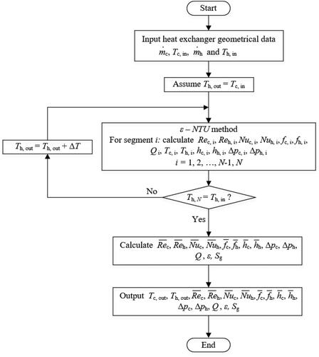
The output parameters of the modeling for overall thermohydraulic performance, such as heat exchanger effectiveness, heat transfer rate, and entropy generation rate, are obtained as:
(33)
(33)
(34)
(34)
(35)
(35)
To demonstrate the heat transfer enhancement of the zigzag channels and the separator sheets, the augmentation entropy generation number () proposed by Bejan [Citation29] is employed, by comparing the irreversibility rate between PCHE-ZC and PCHE-SC, and between MTHE-SS and MTHE, respectively. The
s of PCHE-ZC and MTHE-SS are defined as:
(36)
(36)
(37)
(37)
where
s less than unity represents the capable of heat transfer augmentation.
The input parameters for the modeling are: Tc, in = 100 °C, Th, in = 400 °C, pc, in = 150 bar, ph, in = 75 bar, and varied mass flow rate c, in =
h, in =
= 0.4 or 0.8 kg/s. The heat exchanger length was varied from 0.1 to 2 m in steps of 0.1 m. The channel number is 2000 (1000 on the cold side and 1000 on the hot side) for both PCHE-SC and PCHE-ZC, and the tube number is 1000 for MTHE and MTHE-SS. The inlet mass flux and Reynold number on both cold and hot sides is illustrated in . The modeling code was written and solved using the MATLAB programming language (MathWorks Inc, Natick, Massachusetts, United States).
Table 2. Inlet mass flux and Reynold number on both cold and hot sides.
Results and discussion
Model validation
The model was validated against results of a recuperative heat exchanger published by Guo and Huai [Citation24]. Characteristics of the heat exchanger are plate thickness 2.5 mm, horizontal semi-circular channel pitch 3 mm, channel diameter 2 mm, and total number of channels 3000 (1500 on cold side and 1500 on hot side). The test parameters were: Tc, in = 80 °C, Th, in = 180 °C, pc, in = 200 bar, ph, in = 75 bar, mass flow rate c, in = 1.3 kg/s and
h, in = 2 kg/s. The results of Guo and Huai [Citation24] was validated by comparisons with Kroeger’s analytical solutions [Citation30]. The average relative error between their solutions and the analytical solutions is less than 1.0%. shows the comparisons of the overall heat transfer Q and the total entropy generation number
sT (
) between the present modeling and results from Guo and Huai [Citation24]. The difference is less than 2.0% for both the Q and
sT, confirming the validity of the modeling approach.
Figure 4. Comparison of predicted results with Guo and Huai [Citation24] (a) Variation of Q with L, (b) Variation of NsT with L.
![Figure 4. Comparison of predicted results with Guo and Huai [Citation24] (a) Variation of Q with L, (b) Variation of NsT with L.](/cms/asset/c3c1fc1f-4b65-4e8c-8bb1-80a80830d14a/uhte_a_1943833_f0004_c.jpg)
Average thermohydraulic performance of PCHE-SC and PCHE-ZC
and show the variation of average thermal performance with heat exchanger length for PCHE-SC and PCHE-ZC, respectively. For the specific mass flow rate and with increasing length of the heat exchanger L, the Nusselt number
on the cold side decreases slowly over a short length and then increases slightly, and that on the hot side increases slightly over the length. These phenomena are mostly caused by the variation of Prandtl number with temperature and to a lesser extent by the Reynold number. For example, for
= 0.8 kg/s, the average Prandtl number
of CO2 on the cold side of the PCHE-ZC decreases from 1.018 at L = 0.1 m to 0.976 at L = 0.4 m and then increases steadily to 1.111 at L = 2 m. On the hot side
increases from 0.751 at L = 0.1 m to 0.849 at L = 2 m; The average Reynold number
on the cold side decreases from 27011 at L = 0.1 m to 26229 at L = 2 m, while on the hot side,
increases from 25467 at L = 0.1 m to 31529 at L = 2 m. Increasing
results in a significantly higher
due to the increased
The heat transfer coefficient
is higher on the cold side than on the hot side mostly due to the higher thermal conductivity of the CO2 at lower temperatures. As illustrated in , the
of PCHE-SC is 14.7% higher on the cold side than that on the hot side at
= 0.4 kg/s and 15.5% higher at
= 0.8 kg/s. For the PCHE-ZC, the difference is 18.6% higher at
= 0.4 kg/s and 15.9% at
= 0.8 kg/s. The
for a designated
stays constant with increasing L but increases with increasing
An increased
also increases the difference of
between the cold and hot sides. For given
and specific L, the PCHE-ZC leads to a significantly larger
than that of PCHE-SC, caused by the zigzag channels. It can be seen from that for
= 0.4 kg/s, the
of the PCHE-ZC is 91.9% higher on the cold side and 85.7% higher on the hot side than those of the PCHE-SC, while for
= 0.8 kg/s, the two percentage differences become 68.4% and 67.9%, respectively.
Figure 5. Average thermal performance for PCHE-SC (a) Variation of with L and
(b) Variation of
with L and
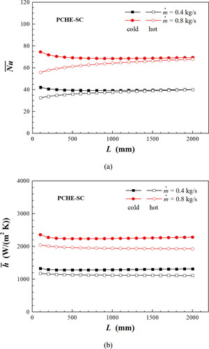
Figure 6. Average thermal performance for PCHE-ZC (a) Variation of with L and
(b) Variation of
with L and
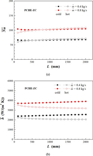
Table 3. Thermohydraulic performance of compact recuperative heat exchangers as L = 1 m.
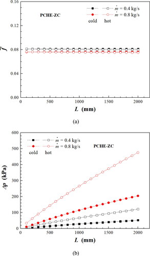
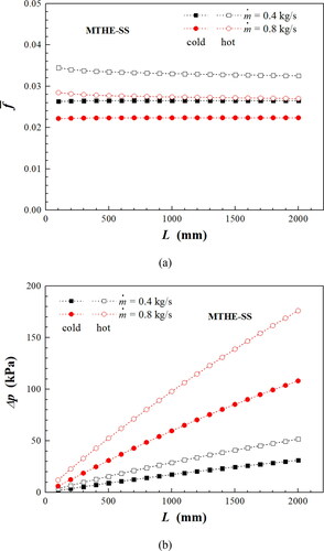
The variations of the average hydraulic performance of PCHE-SC and PCHE-ZC with L are shown in and . The friction factor remains constant with L and decreases with increasing
This decrease is caused by the increase in the
There is little difference of
between the cold and hot sides for both PCHE-SC and PCHE-ZC. However, the
for the PCHE-ZC is much higher than that of the PCHE-SC, and increasing
and increasing L, respectively, lead to largely increases in the pressure drop Δp. Both PCHE-SC and PCHE-ZC show extremely higher Δp on the hot side than the cold side, due to the large increase in density of the supercritical CO2 with pressure. The PCHE-ZC causes much higher Δp than the PCHE-SC due to the higher friction factor and the longer flow passage. The flow passage length of the PCHE-ZC is 1.624 times of the heat exchanger length. illustrates that the PCHE-ZC exhibits more than 6.1 times higher Δp at
= 0.4 kg/s and 7.3 times higher Δp at
= 0.8 kg/s than the PCHE-SC on both the cold and hot sides for a heat exchanger length 1 m.
Figure 7. Average hydraulic performance for PCHE-SC (a) Variation of with L and
(b) Variation of Δp with L and
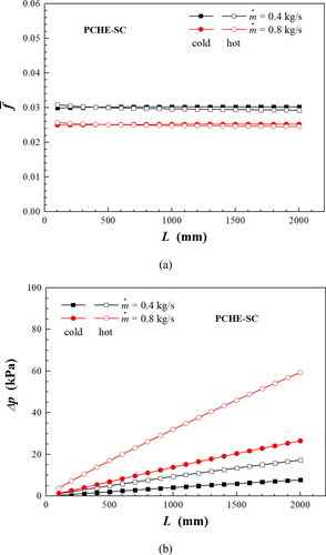
Figure 8. Average hydraulic performance for PCHE-ZC (a) Variation of with L and
(b) Variation of Δp with L and
Overall thermohydraulic performance of PCHE-SC and PCHE-ZC
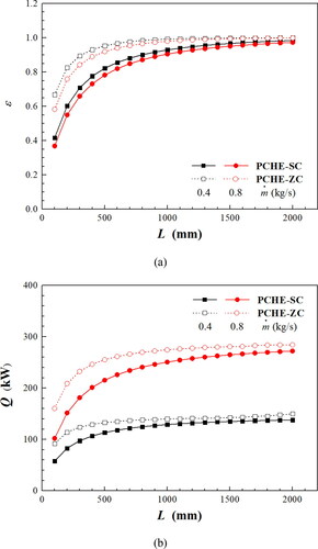
illustrates the variations of heat exchanger effectiveness ε and heat transfer rate Q with L for PCHE-SC and PCHE-ZC. For a specific and increasing L, the ε increases very quickly up to a length of approximately 0.5 m for PCHE-ZC and 1 m for PCHE-SC then begins to flatten out. The effectiveness of the PCHE-ZC increases more sharply than that of the PCHE-SC. For ε = 0.95, the PCHE-SC requires L = 1.2 and 1.5 m for
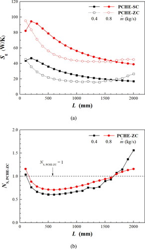
= 0.4 and 0.8 kg/s, respectively, whereas the PCHE-ZC requires L = 0.5 and 0.7 m. The corresponding Q are, respectively, 131.9 and 264.8 kW for PCHE-SC and 132.8 and 266.1 kW for PCHE-ZC. These results demonstrate that the use of PCHE-ZC in sCO2 power cycles can significantly reduce the footprint of the heat exchanger compared to the baseline PCHE-SC. It can also be observed that the heat transfer rate flattens out as the length increases above a certain level, so an optimum length exists for each mass flow rate and thermal load.
Figure 9. Overall heat transfer performance for PCHE-SC and PCHE-ZC (a) Variation of ε with L and (b) Variation of Q with L and
In order to further investigate the overall thermohydraulic performance of the two heat exchangers, compares the variation of the entropy generation rate generated, respectively, by the PCHE-SC and PCHE-ZC. For the PCHE-SC with increasing L, the
first increases to a peak at length between 0.2 and 0.3 m and then begins to drop. The initial increase in
is due to the very fast increase in heat transfer and the fast decrease in temperature difference. As the heat transfer and temperature difference begin to stabilize, the
begins to drop with increasing length until it becomes fairly constant at lengths above 1.5 m. For the PCHE-ZC, the
declines quickly from a maximum to a minimum at around 1 m length and then increases very slightly as the length increases to 2 m. This increase is mostly caused by the large pressure drop with increasing length, particularly at high flow rates. To further illustrate the heat transfer augment of PCHE-ZC than PCHE-SC, the variation of
with L is also demonstrated. With the increase of L, the
firstly decreases and then increases to be larger than unit, indicating the PCHE-ZC can performs better than PCHE-SC but in a limited range of L. It can also be seen that the PCHE-ZC shows worse performance for a larger
where the range of L for
< 1 becomes narrower due to the larger pressure drop. For the studied operating conditions in this article, the PCHE-ZC performs better in the L range of 0.2 to 1.6 m than the PCHE-SC.
Figure 10. Thermodynamic analysis of performance for PCHE-SC and PCHE-ZC (a) Variation of with L and
(b) Variation of
with L and
Average thermohydraulic performance of MTHE and MTHE-SS
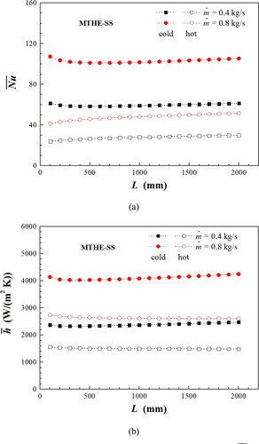
shows the variations of the and
with L for the MTHE, while for the MTHE-SS. The
on the hot side is much lower for the MTHE-SS compared to the MTHE. The introduction of separator sheets between tube rows makes the wetted perimeter P of the hot sCO2 become much larger than that of the MTHE, leading to a smaller hydraulic diameter 0.653 mm compared to 1.559 mm for the MTHE. The much smaller hydraulic diameter further results in the decease of
and
for L = 1 m and
= 0.4 and 0.8 kg/s, the
of the hot sCO2 is 8514 and 16842 for the MTHE-SS, compared to 16993 and 33640 for the MTHE; the corresponding
on the hot side is 27.9 and 48.2 for the MTHE-SS, compared to 48.2 and 81.8 for MTHE. However, the
on the hot side for MTHE-SS is considerably higher than that of the MTHE (1497 W/(m2 K) to 1127 W/(m2 K) at
= 0.4 kg/s and 2619 W/(m2 K) to 1940 W/(m2 K) at
= 0.8 kg/s for L = 1 m as shown in ), resulting from the significantly improved
with decreased D. It can also be noticed that there is little difference between the
and
on the cold side between the MTHE and MTHE-SS, because of the same channel geometry but little difference in pressure and temperature of the CO2.
Figure 11. Average thermal performance for MTHE (a) Dependence of on L and
(b) Dependence of
on L and
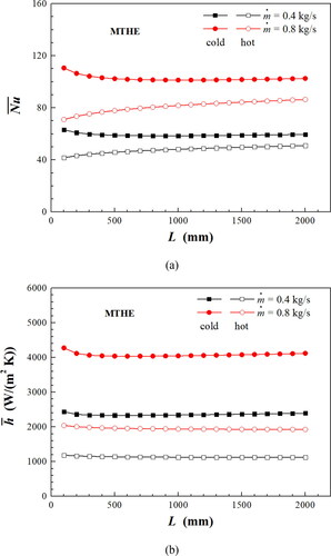
Figure 12. Average thermal performance for MTHE-SS (a) Dependence of on L and
(b) Dependence of
on L and
and present the variation of and Δp, respectively, for the MTHE and MTHE-SS. The two heat exchangers have very similar
and Δp on the cold side, but the MTHE-SS has higher
and Δp on the hot side due to the smaller hydraulic diameter from the introduction of separator sheets. As presented in at L = 1 m, for
= 0.4 and 0.8 kg/s, the Δp of the MTHE is 17.6 and 59.7 kPa, respectively on the cold side and 7.7 and 26.3 kPa on the hot side, whereas for the MTHE-SS the values are 17.4 and 59.8 kPa on the cold side and 29.1 and 97.9 kPa on the hot side.
Figure 13. Average hydraulic performance for MTHE (a) Dependence of on L and
(b) Dependence of Δp on L and
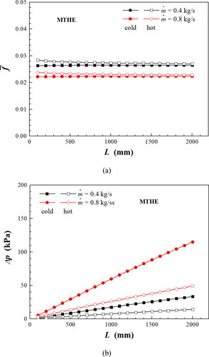
Figure 14. Average hydraulic performance for MTHE-SS (a) Dependence of on L and
(b) Dependence of Δp on L and
Overall thermohydraulic performance of MTHE and MTHE-SS
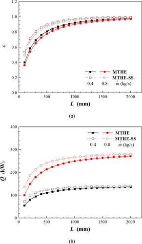
compares the variation of ε and Q with L between the MTHE and MTHE-SS. For specific L, the MTHE-SS shows larger ε than the baseline MTHE, due to its larger and extended heat transfer area on the hot side. For
= 0.4 and 0.8 kg/s, the MTHE requires L = 1.3 and 1.5 m, respectively, to achieve ε = 0.95, whereas the MTHE-SS requires L = 0.8 and 0.9 m. The variation of Q with L also indicates the better overall thermohydraulic performance of the MTHE-SS than the MTHE, especially for shorter L. The difference in the heat transfer performance of the two heat exchangers reduces as the length of the heat exchanger increases. As shown in at L = 1 m, the MTHE-SS transfers 135.4 kW heat as
= 0.4 kg/s and 267.2 kW as
= 0.8 kg/s, compared to 127.8 and 249.5 kW of MTHE.
Figure 15. Overall heat transfer performance for MTHE and MTHE-SS (a) Dependence of ε on L and (b) Dependence of Q on L and
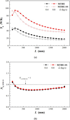
demonstrates the variation of with L for MTHE and MTHE-SS. The
for the MTHE is lower than that of the MTHE-SS over small heat exchanger lengths L < 0.2 m. For L between 0.2 and 2.0 m,
declines faster for the MTHE-SS compared to the MTHE. illustrates the variation of
with L and
For the investigated specifications in this article, the MTHE-SS performs better than the MTHE in the L range between 0.2 and 2 m with best performance at L ∼ 0.75 m.
Figure 16. Thermodynamic analysis of performance for MTHE and MTHE-SS (a) Dependence of on L and
(b) Dependence of
on L and
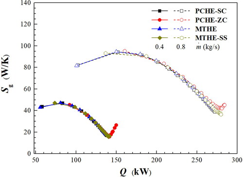
For full comparison of all the four types of recuperative heat exchangers, shows the variation of with Q rather than L. With increasing Q, the
firstly increases slowly, reaches a peak and then decreases quickly for the studied L range. For the PCHE-ZC,
reaches a minimum and then increases again, due to the higher pressure drop for the longer L. The second increase in the PCHE-ZC indicates that the redundant length cannot be beneficial for heat transfer but consumes much more pumping power. The variation of
with Q again indicates the importance of design parameters on the thermohydraulic performance of the recuperative heat exchangers as well as the thermal efficiency and the economic performance of the entire sCO2 waste heat to power conversion systems.
Figure 17. Comparison of with Q for PCHE-SC, PCHE-ZC, MTHE, and MTHE-SS.
Conclusions
This article presents the thermohydraulic modeling and analysis of the performance of four different types of compact recuperative heat exchangers for sCO2 waste heat to power conversion systems: PCHE-SC, PCHE-ZC, MTHE and MTHE-SS. The modeling was based on the segmental approach and the ε-NTU method. Heat exchanger effectiveness, heat transfer rate, entropy generation rate and augmentation entropy generation number have been used as important performance criteria for the comparisons. Based on the modeling results, the following conclusions can be drawn:
The higher mass flow rate leads to higher heat transfer coefficient but significant increase in the pressure drop. As the heat exchanger length increases, the thermohydraulic performance improves up to a certain length and then tails off due to the impact of the increasing pressure drop with length. For the tested operating condition and channel configurations at L = 1 m, the PCHE-ZC leads to 68–92% higher heat transfer coefficient and 6.1–7.3 times larger pressure drop than the PCHE-SC, while the separator sheets on the hot side result in 32–35% higher heat transfer coefficient and 2.72–2.76 times larger pressure drop than the MTHE.
For given heat transfer effectiveness and heat transfer rates the PCHE-ZC and MTHE-SS can have smaller footprint than the corresponding PCHE-SC and MTHE but also higher pressure drops. Under the investigated operating conditions, the PCHE-ZC performs better than the PCHE-SC in the range of 0.2 m < L < 1.6 m, while the MTHE-SS performs better than the MTHE from L = 0.2 m. It is therefore important that in sCO2 heat to power system design a thermoeconomic analysis is carried out to maximize the overall thermal performance whilst at the same time minimizing life cycle cost.
| Nomenclature | ||
| A | = | cross-sectional area of flow, m2 |
| cp | = | specific heat, J/(kg K) |
| C | = | heat capacity rate, W/K |
| = | heat capacity ratio | |
| CFD | = | computational fluid dynamics |
| D | = | hydraulic diameter, m |
| f | = | friction factor |
| G | = | mass flux, kg/(m2 s) |
| h | = | heat transfer coefficient, W/(m2 K) |
| H | = | half height of the fin considering symmetry, m |
| HX | = | heat exchanger segment |
| k | = | thermal conductivity, W/(m K) |
| L | = | length, m |
| = | mass flow rate, kg/s | |
| m | = | dimensional function given by EquationEquation (20) |
| MTHE | = | microtube heat exchanger |
| MTHE-SS | = | microtube heat exchanger with separator sheets |
| N | = | segment number |
| = | augmentation entropy generation number | |
| NsT | = | total entropy generation number |
| NTU | = | number of transfer units |
| Nu | = | Nusselt number |
| P | = | wetted perimeter of the cross section, m |
| PCHE | = | printed circuit heat exchanger |
| PCHE-SC | = | printed circuit heat exchanger with straight channels |
| PCHE-ZC | = | printed circuit heat exchanger with zigzag channels |
| Pr | = | Prandtl number |
| Q | = | heat transfer rate, W |
| R | = | thermal resistance, K/W |
| Re | = | Reynolds number |
| = | entropy generation rate | |
| sCO2 | = | supercritical carbon dioxide |
| T | = | temperature, K |
| U | = | overall heat transfer coefficient, W/(m2 K) |
| Greek symbols | ||
| ρ | = | density, kg/m3 |
| μ | = | dynamic viscosity, Pa·s |
| δ | = | fin thickness, m |
| ɛ | = | effectiveness |
| ηf | = | fin efficiency |
| Δp | = | pressure drop, Pa |
| ΔT | = | temperature difference, K |
| Subscripts | ||
| c | = | cold |
| f | = | fin |
| h | = | hot |
| i | = | segment number |
| max | = | maximum |
| min | = | minimum |
| s | = | stainless steel |
| Superscripts | ||
| ̶ | = | average |
Acknowledgments
The authors would like to acknowledge the financial support received by the project funders and industry partners. All data used are in the article but if any additional information is required it can be obtained by contacting the corresponding author.
Additional information
Funding
Notes on contributors

Lei Chai
Lei Chai is a research fellow at the Institute of Energy Futures, Brunel University London. He received his BSc degree in oil and gas storage and transportation engineering in 2007 from the China University of Petroleum (East China) and his PhD degree in thermal energy engineering in 2012 from Beijing University of Technology. He has published over fifty international journal and conference papers. His research interests are in the field of CO2 power and refrigeration systems, energy storage devices and systems, heat transfer enhancement, and novel heat exchangers.

Savvas A. Tassou
Savvas A. Tassou is the Director of the Institute of Energy Futures and the Director of the Center for Sustainable Energy Use in Food Chains, Brunel University London. He has over 30 years research experience in the area of thermal and energy engineering, covering heating and cooling systems, including heat pump and refrigeration technologies. More recently, his research has also extended to waste heat recovery from industrial processes and waste heat to power conversion using innovative heat exchangers and the sCO2 heat to power cycle.
References
- K. Brun, P. Friedman, and R. Dennis, Fundamentals and Applications of Supercritical Carbon Dioxide (sCO2) Based Power Cycles, Cambridge, UK: Woodhead Publishing, 2017.
- S. A. Wright, C. S. Davidson, and W. O. Scammell, “Thermo-economic analysis of four sCO2 waste heat recovery power systems,” presented at the 5th International sCO2 Symposium, San Antonio, Texas, USA, Mar. 29–31, 2016.
- M. Marchionni, G. Bianchi, and S. A. Tassou, “Techno-economic assessment of Joule-Brayton cycle architectures for heat to power conversion from high-grade heat sources using CO2 in the supercritical state,” Energy, vol. 148, pp. 1140–1152, 2018. DOI: https://doi.org/10.1016/j.energy.2018.02.005.
- V. Dostal, M. J. Driscoll, and P. Hejzlar, “A supercritical carbon dioxide cycle for next generation nuclear reactors,” Massachusetts Institute of Technology, Cambridge, MA, USA, Rep. MIT-ANP-TR-100, 2004.
- L. Chai and S. A. Tassou, “A review of printed circuit heat exchangers for helium and supercritical CO2 Brayton cycles,” Therm. Sci. Eng. Prog., vol. 18, pp. 100543, 2020. DOI: https://doi.org/10.1016/j.tsep.2020.100543.
- Z. H. Ayub, “Recent developments in CO2 heat transfer,” Heat Transfer Eng., vol. 26, no. 6, pp. 3–6, 2005. DOI: https://doi.org/10.1080/01457630590950709.
- Y. Ahn et al., “Review of supercritical CO2 power cycle technology and current status of research and development,” Nucl. Eng. Technol., vol. 47, no. 6, pp. 647–661, 2015. DOI: https://doi.org/10.1016/j.net.2015.06.009.
- S. A. Wright, T. M. Conboy, E. J. Parma, T. G. Lewis, and A. J. Suo-Anttila, “Summary of the Sandia supercritical CO2 development program,” Sandia National Lab, Albuquerque, NM, USA, Rep. SAND2011-3375C, 2011.
- Heatric Division of Meggitt (UK) Ltd. Available: http://www.heatric.com.
- K. Nikitin, Y. Kato, and L. Ngo, “Printed circuit heat exchanger thermal–hydraulic performance in supercritical CO2 experimental loop,” Int. J. Refrigeration, vol. 29, no. 5, pp. 807–814, 2006. DOI: https://doi.org/10.1016/j.ijrefrig.2005.11.005.
- T. L. Ngo, Y. Kato, K. Nikitin, and T. Ishizuka, “Heat transfer and pressure drop correlations of microchannel heat exchangers with S-shaped and zigzag fins for carbon dioxide cycles,” Exp. Therm. Fluid Sci., vol. 32, no. 2, pp. 560–570, 2007. DOI: https://doi.org/10.1016/j.expthermflusci.2007.06.006.
- W. Chu, X. Li, Y. Chen, Q. Wang, and T. Ma, “Experimental study on small scale printed circuit heat exchanger with zigzag channels,” Heat Transfer Eng., vol. 42, no. 9, pp. 723–735, 2021. DOI: https://doi.org/10.1080/01457632.2020.1735779.
- P. M. Fourspring, J. P. Nehrbauer, S. Sullivan, and J. Nash, “Testing of compact recuperators for a supercritical CO2 Brayton power cycle,” presented at the Proceedings of the 4th International Symposium on Supercritical CO2 Power Cycles, Pittsburgh, Pennsylvania, USA, Sept. 9–10, 2014.
- L. Chordia, M. A. Portnoff, and E. Green, “High temperature heat exchanger design and fabrication for systems with large pressure differentials,” Thar Energy, LLC, Pittsburgh, PA (United States), Rep. DE-FE00024012, 2017.
- L. Chai and S. A. Tassou, “Numerical study of the thermohydraulic performance of printed circuit heat exchangers for supercritical CO2 Brayton cycle application,” Energy Procedia, vol. 161, pp. 480–488, 2019. DOI: https://doi.org/10.1016/j.egypro.2019.02.066.
- D. E. Kim, M. H. Kim, J. E. Cha, and S. O. Kim, “Numerical investigation on thermal-hydraulic performance of new printed circuit heat exchanger model,” Nucl. Eng. Des., vol. 238, no. 12, pp. 3269–3276, 2008. DOI: https://doi.org/10.1016/j.nucengdes.2008.08.002.
- S. M. Lee and K. Y. Kim, “Multi-objective optimization of arc-shaped ribs in the channels of a printed circuit heat exchanger,” Int. J. Therm. Sci., vol. 94, pp. 1–8, 2015. DOI: https://doi.org/10.1016/j.ijthermalsci.2015.02.006.
- S. M. Lee and K. Y. Kim, “A parametric study of the thermal-hydraulic performance of a zigzag printed circuit heat exchanger,” Heat Transfer Eng., vol. 35, no. 13, pp. 1192–1200, 2014. DOI: https://doi.org/10.1080/01457632.2013.870004.
- S. G. Kim, Y. Lee, Y. Ahn, and J. I. Lee, “CFD aided approach to design printed circuit heat exchangers for supercritical CO2 Brayton cycle application,” Ann. Nucl. Energy, vol. 92, pp. 175–185, 2016. DOI: https://doi.org/10.1016/j.anucene.2016.01.019.
- S. Y. Lee, B. G. Park, and J. T. Chung, “Numerical studies on thermal hydraulic performance of zigzag-type printed circuit heat exchanger with inserted straight channels,” Appl. Therm. Eng., vol. 123, pp. 1434–1443, 2017. DOI: https://doi.org/10.1016/j.applthermaleng.2017.05.198.
- A. Meshram et al., “Modeling and analysis of a printed circuit heat exchanger for supercritical CO2 power cycle applications,” Appl. Therm. Eng., vol. 109, no. Part B, pp. 861–870, 2016. DOI: https://doi.org/10.1016/j.applthermaleng.2016.05.033.
- M. Marchionni, L. Chai, G. Bianchi, and S. A. Tassou, “Numerical modelling and transient analysis of a printed circuit heat exchanger used as recuperator for supercritical CO2 heat to power conversion systems,” Appl. Therm. Eng., vol. 161, pp. 114190, 2019. DOI: https://doi.org/10.1016/j.applthermaleng.2019.114190.
- J. Guo, “Design analysis of supercritical carbon dioxide recuperator,” Appl. Energy, vol. 164, pp. 21–27, 2016. DOI: https://doi.org/10.1016/j.apenergy.2015.11.049.
- J. Guo and X. Huai, “Performance analysis of printed circuit heat exchanger for supercritical carbon dioxide,” J. Heat Transfer, vol. 139, no. 6, pp. 9, 2017. DOI: https://doi.org/10.1115/1.4035603.
- Y. Jiang, E. Liese, S. E. Zitney, and D. Bhattacharyya, “Design and dynamic modelling of printed circuit heat exchangers for supercritical carbon dioxide Brayton power cycles,” Appl. Energy, vol. 231, pp. 1019–1032, 2018. DOI: https://doi.org/10.1016/j.apenergy.2018.09.193.
- D. Fleming, J. Pasch, T. Conboy, and M. Carlson, “Testing platform and commercialization plan for heat exchanging systems for sCO2 power cycles,” presented at the Proceedings of ASME Turbo Expo 2013: Turbine Technical Conference and Exposition, San Antonio, Texas, USA, Jun. 3–7, 2013. DOI: https://doi.org/10.1115/GT2013-95125.
- S. K. Mylavarapu, X. Sun, R. E. Glosup, R. N. Christensen, and M. W. Patterson, “Thermal hydraulic performance testing of printed circuit heat exchangers in a high-temperature helium test facility,” Appl. Therm. Eng., vol. 65, no. 1–2, pp. 605–614, 2014. DOI: https://doi.org/10.1016/j.applthermaleng.2014.01.025.
- V. Gnielinski, “New equations for heat and mass transfer in turbulent pipe and channel flow,” Int. Chem. Eng., vol. 16, no. 2, pp. 359–368, 1976.
- A. Bejan, “Second law analysis in heat transfer,” Energy, vol. 5, no. 8–9, pp. 720–732, 1980. DOI: https://doi.org/10.1016/0360-5442(80)90091-2.
- P. G. Kroeger, “Performance deterioration in high effectiveness heat exchangers due to axial heat conduction effects,” Adv Cryogenic Eng., vol. 12, pp. 363–372, 1967.