
 ?Mathematical formulae have been encoded as MathML and are displayed in this HTML version using MathJax in order to improve their display. Uncheck the box to turn MathJax off. This feature requires Javascript. Click on a formula to zoom.
Abstract
Heat exchangers for supercritical CO2 power generation and waste heat to power conversion systems have a significant impact on the overall cycle efficiency and system footprint. Key challenges for supercritical CO2 heat exchangers include ability to withstand high temperature and high pressure (typical temperature range of heat source 350 to 800 °C and typical required operating pressure range 150 to 300 bars), and large pressure differential between fluid streams. Other requirements are low pressure drop, high effectiveness and high reliability under thermal cycling. This paper presents recent developments in supercritical CO2 heat exchangers in terms of material selection, design, manufacture, and operation. Since heat exchangers represent a significant portion of the total system cost, another key challenge is to find a compromise between the heat exchanger type, cost, durability, and performance. This paper explores heat exchanger technologies, manufacturing techniques and materials for high temperature and high pressure heat exchangers for supercritical CO2 applications. It also identifies technology gaps and research needs to accelerate the development of effective designs to facilitate the commercialization of both supercritical CO2 heat exchanger technologies and power cycles.
Introduction
Supercritical CO2 systems offer the potential benefits of higher thermal efficiencies and greater power density than traditional steam and gas power cycles. The high-pressure operation throughout the system leads to smaller equipment sizes, smaller plant footprint and better operational flexibility that also led to the potential for lower capital cost. Alongside recent developments in high-temperature materials and compact heat exchanger designs, supercritical CO2 power generation and conversion systems are being investigated as a promising technology for many applications including waste heat recovery, concentrated solar power, fossil fuel and nuclear power generation amongst others [Citation1–4]. The Sandia National Laboratory and the Knolls Atomic Power Laboratory in the USA and the Institute of Applied Energy in Japan are amongst the first to test small scale supercritical CO2 integrated systems alongside the development of important components such as turbomachinery and heat exchangers [Citation4–6]. Demonstration of small-scale integrated systems has also taken place in the USA, Japan, Korea, Europe and China. A supercritical CO2 Brayton cycle developed at Brunel University London, UK, is shown in . The design nominal power output of the integrated system is approximately 50 kW. The flue gas stream is employed to simulate the typical waste heat source. The cycle temperatures and pressures at design conditions are shown in .
Figure 1. A supercritical CO2 Brayton cycle developed at Brunel University London, UK. (a) Test facility, and (b) Cycle design conditions.
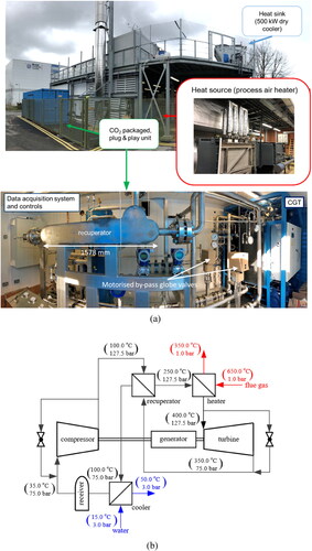
Supercritical CO2 systems, depending on their configuration, can involve many heat exchangers: the heater absorbing heat from the heat source, the recuperator transferring heat from the low-pressure stream to the high-pressure stream, and the cooler rejecting heat to the environment [Citation1, Citation2]. These heat exchangers have a significant impact on system efficiency. This is primarily due to the requirement to maintain cycle compactness, withstand the high temperature and pressure differentials between the fluid streams, and the demands of low pressure drop, high effectiveness and high reliability under thermal cycling. These prerequisites pose significant mechanical, thermomechanical, and thermohydraulic challenges on heat exchanger design [Citation7–11]. In the last couple of decades there has been a prolific increase in research and development of heat exchangers for supercritical CO2 systems. However, most research to date has focused on printed circuit heat exchangers (PCHEs) for recuperator or cooler applications. The development of the heater, particularly for “dirty” exhausts, lags considerably behind recuperator development due to the much higher operating temperatures, larger pressure differential between the hot and cold fluids and fouling issues.
To outline state of the art and highlight challenges to be addressed, this paper presents recent progress on the development of supercritical CO2 heat exchangers and discusses challenges associated with materials, design, manufacture, and operation. The objective is to identify knowledge gaps and research and development needs to address them thus contributing to the global efforts aimed at the further development and commercialization of supercritical CO2 heat to power systems.
Key issues for high temperature and pressure heat exchangers
To facilitate the further development of heat exchangers for supercritical CO2 power generation and conversion systems, it is essential to understand the performance of technologies that have already been commercialized or are close to commercialization, and to resolve key issues of cost and economic viability for commercial-scale deployment. Research to date has shown that the heat exchangers can represent 40-50% of the total system cost [Citation12], leading to another key challenge of finding a compromise between the heat exchanger type, cost, durability, and performance. Moreover, different heat sources and different supercritical CO2 power system layouts impose unique constraints on the heat exchanger design. shows the operating temperature range and shows the required operating pressure range for potential applications of the supercritical CO2 Brayton cycle. The maximum temperature of the heat source can be up to 1500 °C and the operating pressure up to 400 bars. However, due to strength of materials challenges and high cost, current designs of supercritical CO2 Brayton cycles are limited to temperatures below 800 °C and pressures below 300 bars [Citation2, Citation4].
Figure 2. Potential applications relevant to supercritical CO2 Brayton cycle (a) operating temperature range and (b) required operating pressure range. Source data from Reference [Citation10], ARD (advanced reactor designs), ASMR (advanced small modular reactors), GTB (gas turbine bottoming), SP (shipboard propulsion), SHP (shipboard house power), WHR (waste heat recovery), CSP (concentrated solar power), GT (geothermal), IHFF (indirect heating fossil fuel), DHFF (direct heating fossil fuel).
![Figure 2. Potential applications relevant to supercritical CO2 Brayton cycle (a) operating temperature range and (b) required operating pressure range. Source data from Reference [Citation10], ARD (advanced reactor designs), ASMR (advanced small modular reactors), GTB (gas turbine bottoming), SP (shipboard propulsion), SHP (shipboard house power), WHR (waste heat recovery), CSP (concentrated solar power), GT (geothermal), IHFF (indirect heating fossil fuel), DHFF (direct heating fossil fuel).](/cms/asset/b0166250-2fbb-4a6e-8f9a-5bb849ead3a0/uhte_a_2164683_f0002_c.jpg)
Heater
Depending on the heat source, two types of heat exchanger are typically employed: one absorbing the thermal energy from the heat source by combining radiation and convection while the other relying mainly on heat transfer by convection [Citation2]. A heater combining radiation and convection heat transfer has been proposed for coal fired supercritical CO2 power plants [Citation13, Citation14]. Heaters relying only on heat transfer by convection, have been proposed mainly for waste heat recovery applications [Citation9, Citation15]. The following discusses key issues from these applications.
Firstly, material performance and code qualifications need to be addressed. The operation environment requires the material to be able to endure the high temperature and high pressure and withstand fast transients at startup, shut down and changes in operating conditions whilst delivering long enough lifetime. These requirements demand heaters to have large enough heat transfer areas, thick enough walls and be corrosion resistant. At heat source temperatures below 600 °C, stainless steel 316/316 L/347 can be employed. At higher temperatures, nickel alloys, such as Alloy 625 or 617, may be feasible. However, not sufficient experimental data exist for supercritical CO2 heater heat exchangers at high temperatures due to the general lack of high temperature experimental test facilities. The impact of exhaust gas impurities and fabrication approaches on alloy corrosion, strength and durability have also not been well defined as yet. The capital cost of alloys could also hinder their use by industry for the further development of supercritical CO2 technologies [Citation16].
Procedures for manufacturing and assembly also need to be developed for every expected material combination. After manufacturing and assembly, the material strength and durability could be lower than that reported by the manufacturer from sample tests. A critical issue particularly occurs in the joining between the high strength alloys and other materials [Citation10]. The difference in their ionization tendency can also cause corrosion at the interface. The chromium element in the alloys can significantly affect the welding characteristics. The nickel, manganese and molybdenum elements have some influence on the oxide slag during melting. Other residual elements in stainless steels such as carbon, phosphorus, selenium, and sulfur are also important in welding, although their effect is still uncertain.
Thermohydraulic challenges impose requirements of very high heat flux, and large pressure differential between the heat source and supercritical CO2. Further, the heat source can be fossil, nuclear, solar or waste heat and the heating fluid can be fuel gas, molten salt, heat transfer oil, even liquid metals. Different heating fluids demonstrate different thermohydraulic performance and impose different constraints on heater design. The heater must be matched to the heat source and provide adequate heat transfer characteristics and low-pressure drop on both heat transfer sides [Citation13]. These requirements increase the cost of manufacture and thus the design of heaters requires a compromise between good thermohydraulic performance and cost without compromising operational, safety and environmental impacts.
The heater must withstand rapid startups and transients during operation, as well as thermal cycling and fatigue. A transient response can result in a quick temperature rise or drop. The operational problems caused by thermal stresses significantly impact the durability of the heater [Citation17]. To ensure reliable, repeatable, and safe cyclic operation, it is necessary to develop procedures of repeated startup and shutdown tests for different heat sources before heaters are deployed in service [Citation1].
Recuperator
Depending on operating conditions and heat exchanger performance, over 60% of the heat addition to the compressor discharge is achieved through recuperation, while the remaining is provided by the heat source [Citation10]. The objectives of recuperator design are to maximize heat transfer efficiency, minimize pressure drop, and ensure even flow distribution. Challenges facing recuperators are the requirements to withstand high temperature and large pressure differentials, flow passage design to improve thermohydraulic performance and reduce pressure drop and need to reduce capital cost.
The erosive and corrosive degradation of materials of recuperators are similar to those in the heater, but at lower temperature and lower pressure differentials between the fluid streams. The employed material should be selected based on operating temperature, operating pressure, fouling and corrosion resistance [Citation18, Citation19].
Most supercritical CO2 systems employ the Printed Circuit Heat Exchanger (PCHE) as recuperator, due to the need for compact and high-performance heat exchangers. PCHEs are normally manufactured using diffusion-bonding, and the process employed has much influence on their performance. The surface preparation of the boned plates is critical and difficult, and the boned size is limited by the manufacturing equipment available. In addition, the manufacturing process does not provide easy access to examining the internal channels and the heat exchanger cannot be disassembled for cleaning or maintenance [Citation20].
Key issues remaining to be addressed with PCHE recuperators are high capital cost and uncertainty around mechanical performance and thermal fatigue. To improve the recuperative performance, zigzag channels, S-shaped channels, and channels with airfoil fins have been developed. Such methods do improve the heat transfer performance, but also contribute to larger pressure drop due to the bends present in the flow path. Further, most of the developed empirical correlations of heat transfer and pressure drop are not universal but for specific flow passages. This makes it difficult to further optimize PCHE design and multi-objective optimization research is necessary to achieve this [Citation8].
High thermal stresses can influence the durability of the recuperator that should achieve sufficiently long operating life, typically 90,000 hours of operation and 10,000 cycles. The influence therefore of cyclic operation on burst strength, creep, and fatigue, are areas that merit significantly further investigation [Citation17].
Cooler
Due to lower temperatures and pressures, concerns about material selection and manufacturing of the coolers are much less. Heat exchanges developed and being used in CO2 refrigeration and heat pump systems are mostly suitable for this application. The biggest concern in the cooler is the CO2 temperature and pressure close to the critical point, where the pinch point can affect the heat transfer effectiveness and total heat rejected to the cooling fluid as well as how fast the temperature of CO2 entering the compressor can be controlled [Citation21].
The cooling fluid can be either air or water, and the differing thermophysical properties can also significantly affect the cooler geometry and performance. The air-coupled coolers usually require large heat transfer areas due to the thermophysical properties of air, and some investigators have questioned the practicality of air cooling in supercritical CO2 systems [Citation22]. Reduction of the surface area can be achieved by reducing coil diameter and tube spacing, while other challenges include heat transfer enhancement on the air side and optimization of the tube circuitry to alleviate pinch point problems and minimize pressure drop and footprint. For water-coupled coolers, the risk of leakage between the two fluids during operation is an important consideration. Corrosion of copper solder or steel plates caused by impurities in the water, including chlorides, sulfites, iron, conductivity, pH value, etc., can cause the corrosion of copper solder or steel plates.
High temperature and pressure compact heat exchangers currently in use
Currently, the most common compact heat exchangers for supercritical CO2 applications include PCHEs, diffusion-bonded plate-fin heat exchangers, and micro shell and tube or microtube heat exchangers. details their principal features, including maximum temperature, maximum pressure, and maximum surface area density.
Table 1. Developed high temperature and pressure heat exchangers for supercritical CO2 applications.
Printed circuit heat exchanger (PCHE)
PCHE is a diffusion-bonded microchannel heat exchanger that can achieve high heat transfer effectiveness. As shown in , a typical PCHE is fabricated from a number of substrate plates where the flow passages are manufactured by photochemical machining. The plates are stacked together and diffusion-bonded to form compact, very strong, all-metal heat exchanger cores. The authors have reviewed material selection, manufacture, and assembly, thermohydraulic performance and geometric optimization of PCHEs for helium and supercritical CO2 Brayton cycles in an earlier publication [Citation8]. Therefore, in this paper the focus is on progress since 2019, and in particular on the influence of flow passages: straight channel, zigzag channel, channels with S-shaped fins, and channels with airfoil fins shown in , on PCHE performance.
Figure 3. Typical PCHE (a) flow paths and (b) diffusion-bonded core (courtesy of Heatric Meggitt UK).
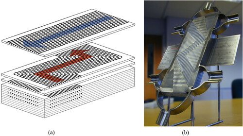
Figure 4. Etched flow paths of PCHEs: (a) straight channel, (b) zigzag (or wavy) channel, (c) channel with S-shaped fins, and (d) channel with airfoil fins.

Liu et al. [Citation23, Citation24] performed experimental investigations on the thermohydraulic performance of a printed circuit cooler, with supercritical CO2 rejecting heat to water. The PCHE had straight semi-circular channels of diameter 1.87 mm and pitch along the cross section of 2.7 mm. To determine the local heat transfer coefficient, six temperature measurement locations were used along the CO2 flow direction. The data was used to determine a correlation for the local heat transfer coefficient which was found to predict 92.4% of the data within ± 30% of the error band. Heat transfer enhancement was found to occur when the supercritical CO2 was cooled from the gas-like zone to the pseudo-critical zone. At this point, the LMTD between the water and CO2 were found to be minimum. Park et al. [Citation25] investigated the heat transfer and flow characteristics of supercritical CO2 near the critical point in a printed circuit CO2-water heat exchanger with straight channels. To account for the significant changes in the properties of CO2 near the critical point, they developed a discretization method for data reduction and compared the results with the more conventional method of using average inlet and outlet property values. The results showed only a small difference between the two methods at conditions away from the critical point. However, at conditions close to the critical point, the Nusselt number calculated using the discretization method was found to be more than double that calculated with the averaging method. This demonstrates that the discretization method is more appropriate for Nusselt number calculations close to the critical region.
For numerical investigations and theoretical models, Zhang et al. [Citation26] analyzed the effect of buoyancy on the heat transfer characteristics of supercritical CO2. They found that buoyancy can improve the heat transfer on the top wall but reduce it on the bottom wall on the hot side, while on the cold side the effect is exactly the opposite. The buoyancy effect becomes smaller with increasing CO2 mass flow rate. Chai and Tassou [Citation27] investigated the thermohydraulic performance of supercritical CO2 flow in a PCHE. Their numerical model takes into consideration entrance effects, conjugate heat transfer and buoyancy effects. The average heat transfer and friction pressure drop as well as the overall performance of the heat exchanger are discussed. Sarmiento et al. [Citation28] presented a theoretical model to predict the thermohydraulic behavior of PCHEs. It is a one-dimensional steady-state thermal model based on channel geometry parameters and fundamental heat transfer and friction factor equations. Good agreement was found between the test data and the models for both the heat transfer and flow performance.
Torre et al. [Citation29] investigated numerically thermal stresses in PCHEs for different temperature gradients and geometric parameters. A proportional relationship was observed between the thermal stress and the thermal gradient between channels. Chu et al. [Citation30] investigated the thermohydraulic performance of a printed circuit cooler with zigzag channels for heat transfer between supercritical CO2 and water at pressures ranging from 8.0 to 11.0 MPa on the CO2 side. The major convective thermal resistance was found on the supercritical CO2 side. Increasing the operating pressure leads to increased heat transfer coefficient but also pressure drop. Li et al. [Citation31] examined the effect of CO2 inlet temperature and pressure on the overall heat transfer performance of a CO2-water precooler. They found that increasing the inlet temperature of CO2 decreases the overall heat transfer coefficient but increasing the mass flow rate and operating pressure improves it. Cheng et al. [Citation32] analyzed the influence of the inlet temperatures and Reynolds number on the exergy loss and efficiency of a printed circuit recuperator. Lower Reynolds number and higher inlet temperature on the cold side was found to result in a higher exergy efficiency. Zhou et al. [Citation33] investigated the heat transfer effectiveness, pressure drop and heat load of a 100 kW printed circuit recuperator. For numerical investigations and theoretical models, Ren et al. [Citation34] and Saeed et al. [Citation35] respectively investigated the local flow and heat transfer of supercritical CO2 during cooling near the critical or pseudo-critical point. The thermophysical property variations, mass flux, pitch length, and inclined angles of the zigzag channels can significantly affect the flow and heat transfer. Zhang et al. [Citation36] investigated the effect of bend angle of zigzag channel on the thermohydraulic performance as supercritical CO2 near the critical or pseudo-critical point. The reduction of the zigzag bend angle leads to improvement of heat transfer performance, but larger pressure drop. Bend angles between 110° to 130° were found to produce best performance. Wen et al. [Citation37] investigated the flow and heat transfer characteristics of sinusoidal and zigzag channels. The sinusoidal channel can significantly reduce the pressure drop while keeping almost the same heat transfer performance compared to the zigzag channel. Marchionni et al. [Citation38] employed a one-dimensional dynamic model to investigate the heat transfer processes in a supercritical CO2 printed circuit recuperator at design and off-design operating conditions. Dynamic simulations under transient operating conditions show that the thermal expansion of the working fluid resulting from the fast-reducing density and increased pressure can be a concern, and careful management of the startup of supercritical power cycles to avoid sudden changes in temperature and thermal stresses are required. Yang et al. [Citation39, Citation40] employed a multi-objective evolutionary algorithm for optimization to improve the overall thermohydraulic performance of a printed circuit recuperator. Saeed et al. [Citation41] also undertook a multi-objective optimization study to determine a balance between the size of the PCHE and its performance. Five different fin configurations including straight, zigzag, C-shaped, S-shaped, and airfoil were compared. The C-shaped and zigzag channel geometries resulted in maximum efficiency and minimum size.
Saeed and Kim [Citation42] also employed a response surface methodology combined with a genetic algorithm to optimize the channel geometry of a recuperator with staggered sinusoidal fins. The optimized channel geometry showed much better overall thermohydraulic performance, up to 21% and 16% higher for the cold and hot side respectively compared to the conventional zigzag channel geometry.
Chu et al. [Citation43] investigated the thermohydraulic performance of PCHE with supercritical CO2 flow in channels with airfoil fins. The airfoil fins resulted in improved heat transfer performance but increased pressure loss than symmetrical fins. Shi et al. [Citation44] studied the flow and heat transfer performance of a supercritical CO2 and molten salt PCHE with airfoil, zigzag and straight fins. The channels with the airfoil fins showed best overall heat transfer performance. Increasing inlet temperature improved the heat transfer performance of the molten salt but reduced the performance of supercritical CO2. Wang et al. [Citation45] investigated experimentally the performance of PCHEs with molten salt on the hot side and synthetic oil on the cold side with distributed airfoil fins on the hot side and straight fins on the cold side. Hot side temperature and Reynolds number were varied between 198 °C and 254 °C and between 500 to 1548 respectively. The channels with airfoil fins showed better heat transfer performance than the channels with straight fins.
The results of recent studies on the thermohydraulic characteristics of PCHEs are summarized in [Citation23–28, Citation30–39, Citation42–44], and a summary of heat transfer and friction factor correlations developed since 2019 is given in [Citation23, Citation24, Citation30, Citation32, Citation34, Citation35, Citation44]. It is important to point out that these correlations have been developed for specific flow passages and operating conditions and using thermophysical properties corresponding to the average temperature of channel inlet and outlet. When these correlations are used for heat exchanger design, care should be taken that conditions are similar to those for which the developed correlations were based on.
Table 2. Representative studies of thermohydraulic characteristics of supercritical CO2 in printed circuit heat exchanger.
Table 3. Correlations of friction factor and heat transfer during supercritical CO2 flowing in PCHEs.
Diffusion-bonded plate-fin heat exchanger
The diffusion-bonded plate-fin heat exchanger is a type of compact heat exchanger that consists of a stack of alternate flat plates and corrugated fins, and the joining is accomplished by diffusion bonding to form a solid block of metal with flow passages passing through it. The thermal operational limits of the plate fin style cores depend on the type of materials used and are generally more suitable to lower pressure applications up to 200 bars, which are lower than those of printed circuit style cores [Citation46]. Plain, perforated, offset-strip, louvered, wavy fin geometries have been used in the design of plate-fin heat exchangers for heat transfer enhancement. Plate-fin heat exchangers have been applied in power and energy industries, and a growing research activity is under way on the development of diffusion-bonded plate-fin heat exchangers for supercritical CO2 cycles. The supercritical CO2 flows through the internal fin-supported passages and distributes and collects at the two ends of the header blocks, while the hot air or flue gas flow crosses between the fins. However, studies on general fin performance and applicable fin selection strategies at high temperature and high pressure are limited.
Sullivan et al. [Citation17] developed an internally supported plate-fin compact heat exchanger as supercritical CO2 recuperator and investigated its mechanical performance including burst strength, creep, and fatigue. The extrapolated section stress of 67.84 MPa suggested creep life can be up to 1,000,000 hours and the anticipated peak stress of 157.8 MPa suggested fatigue life up to 200,000 cycles. The authors also suggested that the fin thickness and fin density should be selected based on the specified life targets and the heat exchanger operating conditions. Tioual-Demange et al. [Citation47, Citation48] also designed a supercritical CO2 plate-fin recuperator and tested its mechanical performance. A bursting test pressure of 800 bars was reached. Sullivan et al. [Citation49] used Alloy 625 for the manufacture of a plate-fin heat exchanger to be used as heater in supercritical CO2 solar power applications. The heat exchanger was designed to withstand temperatures up to 750 °C and pressures of up to 277 bars based on fatigue and creep considerations. The bursting pressure was found to exceed 800 bars.
Bartel et al. [Citation50] investigated the helium-helium recuperative thermohydraulic performance of an offset strip-fin heat exchanger and PCHEs for advanced nuclear reactors. Results indicate that the offset strip-fin heat exchanger may offer high surface area to volume ratio, high thermal effectiveness, and overall low pressure drop, but as yet do not match the performance PCHEs with zigzag channels. Jiang et al. [Citation51] investigated the thermohydraulic characteristics of helium flowing through plate fin heat exchangers with offset-strip fins. The heat transfer performance was found to deteriorate gradually with the temperature decrease, and the friction factor increased slightly at low temperatures and more sharply at lower Reynold numbers, due to increase in the Prandtl number and decrease in thermal conductivity. They suggested that the Reynold number, fin spacing, and thickness are important parameters in the optimization of plate heat exchangers with offset-strip fins.
Micro shell and tube or microtube heat exchanger
Micro shell and tube heat exchangers are of shell and tube design with micro-tubes. The high-pressure fluid is flowing through the micro-sized tubes and the low-pressure fluid flows through the shell. The advantages of this micro design include high heat transfer efficiency, ease of maintenance, and meeting high temperature and high differential pressure criteria [Citation7].
Thar Energy LLC has developed a counter-current microtube recuperator and a cross flow, counter-current, micro-tube heat exchanger for supercritical CO2 heater applications. They also built a heat exchanger test loop that can accommodate test pressures up to 275 bars and temperatures up to 700 °C to characterize recuperator and heater heat exchangers [Citation11]. The recuperator has an area density of 4500 m2/m3 and is made of Inconel 625. The low-temperature and high-pressure supercritical CO2 flows inside the microtubes and the high-temperature and low-pressure supercritical CO2 flows in the shell side. The two supercritical CO2 flows are also separated by a tube sheet. The heater has an area density of 1800 m2/m3 and is made of Inconel 625 and stainless steel 316. The supercritical CO2 flows inside the microtubes and the air in the shell side. The thermohydraulic performance of the recuperator and the air-to-CO2 thermohydraulic performance of the heater were tested in the test loop. They suggested that microtube heat exchangers have the potential to replace PCHEs, due to their potential to satisfy the high temperature and high pressure differential criteria but at much lower capital cost. Exergy LLC (www.exergyllc.com) and Tokyo Titanium (http://tokyo-titanium.com) also developed micro shell and tube heat exchangers for CO2 applications.
Chai and Tassou [Citation52] investigated the recuperative thermohydraulic performance of microtube heat exchangers with and without separator sheets based on modeling using the segmental approach and the ε-NTU method. The separator sheets improve the heat transfer coefficient of the shell side and increase the heat transfer area but increase the friction factor. This leads to smaller footprint, but higher pressure drops than microtube heat exchangers without separator sheets for a given heat transfer effectiveness and heat transfer rate.
Cai et al. [Citation53] experimentally investigated the heat transfer and pressure drop characteristics of supercritical CO2 and water in microtube heat exchangers with and without baffles. The microtube heat exchanger consisted of 37 stainless steel tubes with length of 500 mm, outer diameter of 2 mm and wall thickness 0.2 mm. Baffles on the shell side significantly enhanced the heat transfer on the water side but also led to larger pressure drop. The inlet and outlet pressure drop of supercritical CO2 in the tube side was found to be much larger than that of conventional shell and tube heat exchangers due to the welding process employed.
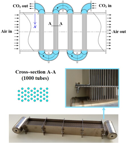
A microtube heater, shown in has been developed for Brunel University London by Reaction Engines (https://reactionengines.co.uk) for heat recovery applications. The supercritical CO2 is designed to flow through the micro tubes and the flue gas across the tube bundles. The microtubes have outside diameter of 2 mm, wall thickness of 0.1 mm, and tube length of 0.5 m. The test of its thermohydraulic performance is in progress.
Figure 5. Microtube heater (courtesy of Reaction Engines Ltd).
To illustrate the advantages and drawbacks of developed microtube heat exchangers for supercritical CO2 heat exchangers, a comparative summary is given in .
Table 4. Main advantages and drawbacks of developed heat exchangers for supercritical CO2 applications.
Potential heat exchanger designs, materials and fabrication methods
High performance, compact, low cost, large capacity heat exchangers are required by supercritical CO2 power generation and conversion systems. With these requirements in mind, engineers and scientists have continued to conduct research to identify potential concepts to improve heat exchanger performance, counteract fouling problems, save space, reduce cost, and increase efficiency. Three approaches offering potential to address these challenges are: i) the use of additive manufacturing for the manufacture of 3 D printed heat exchangers; ii) investment casting of metal heat exchangers; iii) manufacture of ceramic heat exchangers by laminated-object or additive manufacturing.
3D printed heat exchanger
Additive manufacturing is the process of joining materials layer upon layer to make objects from 3 D model data [Citation54]. This process is a versatile, flexible, highly customizable fabrication method and can suite most sectors of industrial production. This fabrication method is crucial for developing the next-generation heat exchangers, which has the significant potential to facilitate the development of the high-efficiency heat exchangers due to the complex, geometric freedom this manufacturing technique offers [Citation55, Citation56]. Different from traditional manufacturing where heat exchangers are made from thin sheets of material that are welded or brazed together, additive manufacturing systems build heat exchangers layer-by-layer with only adding material where needed and can produce lightweight yet complex heat exchangers. The digitally driven process employed in additive manufacturing gives the engineers the design freedom to create heat exchangers with complex structures that would never be possible with traditional machining. Additively manufactured heat exchangers have the potential for less material, reduced volume, increased thermal performance, increased reliability, compared to conventional heat exchangers and the process, to-date, has been used with metals, polymers, and ceramics [Citation57, Citation58].
Additive manufacturing has been successfully employed for the fabrication of heat sinks from aluminum and copper for electronic cooling applications [Citation59] and many other heat transfer devices from stainless steel, nickel and titanium alloys for thermal energy conversion applications [Citation60]. Despite the impressive progress made to date, the development of additively manufactured heat exchangers for supercritical CO2 applications, has been slow owing to the very demanding performance requirements. For supercritical CO2 recuperator application, researchers investigated the manufacture of additively manufactured tubes with internal pin fins [Citation61]. All the tubes were made of 316 stainless steel and had an inner diameter of 7 mm and a wall thickness of 1.2 mm. The tube length was limited to 127 mm due to limitations in the volume chamber. For heat transfer enhancement due to swirl flow, the circular or elliptical pins in cross-section were printed at a 30° angle relative to the inner wall and with helical arrangement. The test pressure was up to 207 bars. The pins were found to significantly improve the heat transfer but caused much higher pressure drops. The tubes with pins were estimated to decrease the required heat exchanger material by 13%. A prototype of additively manufactured heat exchanger has also been designed by General Electric (GE) for supercritical CO2 power generation [Citation62]. GE (https://www.ge.com/) expect the lung-inspired 3 D additively manufactured heat exchanger to play a key role in building a supercritical CO2 demonstration plant capable of generating 10 megawatts of electrical power.
Despite the recent progress, there are still significant technical challenges to overcome before additive manufactured CO2 heat exchangers become a commercial reality. During manufacture, the material experiences complex thermal processing cycles which impact the properties of the developed device, like hardness and corrosion resistance and needs to be taken into consideration [Citation63]. Some studies have also found deviation of experimental results of thermal properties of the material from those published by the manufacturers of the materials [Citation64]. The manufacturing process also may lead to parts with internal porosity resulting from shrinkage, gas entrapment during solidification, and adhesion of partially molten particles to surfaces between layers [Citation57]. The porosity greatly influences the thermal conductivity and the tensile and fatigue strength of the fabricated parts [Citation65, Citation66].
Currently available additive manufacturing systems have relatively small effective building volumes, which limit the capability to integrally manufacture large components [Citation67, Citation68]. The current processes are also costly and time-consuming and thus are not suitable for large volume production. The qualification and certification of additive manufactured heat exchangers are also challenging as there are no specific standards for assessing the properties of additively manufactured heat exchangers because they depend on many process parameters [Citation60, Citation69]. Surface roughness and powder removal of additively manufactured heat exchangers are also a challenge that adds to the manufacturing cost and increases pressure drop particularly in the case of mini/microchannel heat exchangers [Citation59, Citation64, Citation70, Citation71].
Casted metal heat exchanger
Investment casting produces patterns using rapid prototyping processes rather than molded wax. The pattern is encased in refractory material, and then burned out to form a mold cavity in the shape of the pattern, and then the mold cavity is filled with molten metal to create the metal part with the similar geometric shapes and size of the patterns [Citation72, Citation73]. The mold surface can have low roughness and the refractory material can offer ample refractory strength and chemical inertness. The technique can make metal components with complex geometry and accurate dimensions, compared to those manufactured with sand casting. Tolerances as low as 76 μm have been claimed and metal components with sections as narrow as 0.4 mm have been manufactured [Citation74, Citation75]. The technique can also make metal parts from various metal alloys including carbon and low alloy steels, stainless steels, tool steels, nickel and cobalt alloys, and aluminum and copper alloys, [Citation76]. It has been used for the production of quality components for many applications in the aerospace, power generation, automotive, gas and oil, and energy industries [Citation74, Citation77].
Most of the metal components produced by investment casting in the power and energy industries are rotors and turbine blades in motors and generators with only very few heat exchangers and heat sinks manufactured to date. Lei et al. [Citation78] fabricated six pin-fin heat sinks for electronics cooling applications and Matz et al. [Citation79] manufactured open-pore metal foams for heat engineering application. For supercritical CO2 applications, investment casted heat exchangers have the potential to offer greater flexibility in material options and channel geometries, similar or better heat transfer capacity, but lower capital cost than PCHEs. The ability to fabricate large heat exchangers with materials that are difficult to machine such as novel high-performance nickel alloys, is particularly attractive. Sandia National Laboratories has employed investment casting to develop S-shaped fin and airfoil fin surface geometries used in PCHEs [Citation80].
Despite its main advantages, the adoption of investment casting for supercritical CO2 heat exchanger applications faces crucial technical challenges. Mismatch in the thermal expansion between the pattern and ceramic shell can cause cracks in the shell [Citation81]. It is also difficult to remove the casting core material from the finished block and relatively significant quantities of residual ash may also cause defects in the final castings [Citation82]. The casting of high-temperature metal may induce porosity which can impact the quality of the fabricated components [Citation75]. Investment casting presents some difficulties where holes or cores are involved with the minimum diameter of casted holes being approximately 1.6 mm [Citation75]. Another major challenge are the long cycle times that require the development of cost-effective solutions for low-volume production to facilitate the commercial application of casted metal heat exchangers [Citation83].
Ceramic heat exchanger
Since the specific strength of metallic materials decreases very rapidly with high temperature and pressure, especially at temperatures over 650 °C, the ceramic heat exchanger may be an economical solution for high temperature applications [Citation84, Citation85]. Ceramic materials offer many benefits for use in heat exchangers, including high temperature thermodynamic stability, high thermal conductivity, high thermal shock resistance, low creep at high temperature, high compressive strength and corrosion and erosion resistance, and ability to operate with high pressure differential between the hot and cold sides [Citation86, Citation87]. Among the structural ceramic materials, silicon carbide-based ceramics have received the most attention and been thought as the most promising heat exchanger materials. They have high temperature of decomposition of around 2500 °C and about four times the thermal conductivity of steel. They also show excellent thermal shock resistance and maintain their flexural strength at elevated temperatures. Ceramic heat exchangers have found applications in the chemical process, power generation and industrial waste heat recovery industries [Citation85, Citation87].
Pioneering work on the development of ceramic heat exchangers can be traced back to the 1980s. Coombs et al. [Citation88] fabricated a ceramic finned-plate recuperator for fluidized-bed waste heat recovery, Kleiner et al. [Citation89] designed a highly compact, all-prime surface, internally manifolded, plate-and-fin ceramic recuperator for engine applications, and Luu and Grant [Citation90] designed a ceramic bayonet tube heat exchanger for high temperature waste heat recovery.
Lewinsohn [Citation86] demonstrated the potential of ceramic microchannel heat exchangers to offer higher efficiency over more conventional designs. A stack of silicon carbide heat exchanger plates and a conceptual design of modular, microchannel plate heat exchanger for a macroscale process have been developed. Sommers et al. [Citation87] reviewed ceramics and ceramic matrix composites for new heat exchanger designs for advanced thermal systems. Scheithauer et al. [Citation91] compared two advanced ceramic heat exchanger fabrication methods, additive manufacturing, and laminated-object-manufacturing, and discussed advantages and limitations. Kee et al. [Citation92] fabricated a kilowatt-scale, compact, alumina ceramic microchannel plate heat exchanger and tested its thermohydraulic performance with hot air up to 750 °C. Haunstetter et al. [Citation93] fabricated ceramic heat exchangers with modified offset-strip-fin design and investigated their thermohydraulic performance with hot air up to 800 °C.
So far, ceramic heat exchangers for supercritical CO2 applications have been tested only under high temperature, but not under both high temperature and high pressure, and little is known regarding the effects of CO2 and exhaust gas species in heat recovery applications on the ceramics. The challenges in the use of ceramic heat exchangers in supercritical CO2 systems are discussed below. Firstly, the difficulty of joining of ceramics to metals. The problems making the joining difficult come from the different thermal expansion coefficient, atom bond configuration, and chemical and physical properties between ceramic and metal materials [Citation94]. Using the general joining method of diffusion bounding and fusion welding to join them together is almost impossible, and the molten metal does not generally wet on ceramic surfaces [Citation95]. Secondly, reliable high temperature, high pressure seals between metal pipes and ceramic heat exchangers. The pressure forces under the seal faces must be balanced and tolerance must be allowed for the thermal distortion of the metal pipes. The seals must be efficient under high temperature, high pressure and high-pressure differential operations and must accommodate the mismatched expansion and contraction of ceramic materials and metal pipes [Citation96]. Thirdly, the lack of ductility and inherent brittleness in tension of the materials that can significantly affect the reliability and consistency of material properties [Citation87]. Finally, the manufacturing costs and methods. Suitable fabrication methods for compact ceramic heat exchanger are additive manufacturing and the laminated-object-manufacturing approach [Citation86, Citation97]. The challenges for additive manufacturing are the molds used for forming ceramic bodies, which are expensive and require a significant number of materials and components to enable the fabrication of dense ceramic parts with optimal properties including density, mechanical strength, surface finish, as well as the production of ceramic components at high volume [Citation90, Citation97]. In the laminated-object-manufacturing approach, ceramic heat exchanger plates are built by lamination of sheet feedstock, and then cut into the desired shape with a computer-controlled laser or blade. Compared to additive manufacturing, the laminated-object-manufacturing approach affords manufacturing of comparatively large-scale at lower cost and convenient processing speed. The challenge of this method is the surface quality and dimensional accuracy of the produced parts. Removal of the laminated supporting material can be tedious and complex undercuts and hollow structures can be very difficult to produce. The joining of the individual heat transfer plates is also a challenge where the joints must have good mechanical properties to withstand the high pressure at elevated temperatures [Citation86, Citation98]. To address the above challenges, further research and development is needed to address issues of ductility and brittleness, joining methods to metallic components and demonstration of reliable manufacturing processes for commercial scale heat exchangers.
The advantages and drawbacks of emerging heat exchangers for supercritical heat exchangers are summarized in .
Table 5. Main advantages and drawbacks of potential heat exchangers for supercritical CO2 applications.
Conclusions and recommendations
This paper provides a comprehensive review of high temperature and high pressure heat exchangers for supercritical CO2 applications, covering key issues associated with the design, manufacture, and operation processes. Major conclusions are:
High-temperature materials and fabrication methods restrict the development of heat exchangers in the supercritical CO2 Brayton cycles. The material performance and code qualification are required to develop material databases and standards. The manufacturing and assembly procedures are expected to exert less influence on material strength and durability.
Design strategy and evaluation criteria are required to balance the heat exchanger type, cost, durability, and performance. The thermohydraulic design demands low pressure drop and high effectiveness. The structural design requires the ability to withstand rapid startups and transients during operation as well as endure thermal cycling and fatigue. The capital cost significantly impacts the process of supercritical CO2 power system development from demonstration to commercialization.
PCHEs are currently the most widely adopted heat exchangers for recuperation in supercritical CO2 applications. Their advantages include compactness and structural rigidity and reliable performance under conditions of high pressure and high temperature. So far, most of the research has focused on thermohydraulic design under steady state operating conditions. Performance under off-design conditions (startup, shutdown, and changes in load) needs to be further investigated due to its influence on other system components and control as well as the influence of thermal cycling on fatigue of the whole heat exchanger, not just that of a single plate.
Diffusion-bonded plate-fin heat exchangers are generally suitable for lower pressure applications, below those employing printed circuit style cores. Further research into the fin selection, fabrication and performance is required, also to establish the pressure and temperature limits of these heat exchangers. Their thermohydraulic performance under transient operating conditions should also be investigated further as well as the thermal stresses and reliability of bonded joints.
Microtube heat exchangers have been developed for both heater and recuperator applications, but more research is required on their performance as well as capital cost. Microtube heaters are usually employed for heating or heat recovery from hot exhaust gas streams. Issues that need further consideration include cleaning of the heat exchangers if they are to be used with “dirty” exhausts and maintenance in the event of tube failure. For recuperative CO2 to CO2 heat transfer applications, microtube shell and tube heat exchangers compete with more established PCHEs and further work is required to investigate their comparative heat transfer and pressure drop performance and capital cost.
The development of additive manufacturing technologies has facilitated the 3D printing of metallic heat exchangers. Advantages include less material use and the ability to manufacture complex and highly efficient designs. The manufacture of large 3D printed heat exchangers is currently hindered by the 3D printing technology available which also reduces the potential for mass production.
Investment casted heat exchangers have the potential to reduce the number and complexity of fabrication steps required compared to alternative heat exchanger manufacturing techniques. However, there are limitations on the size of the flow passages, the size of the heat exchanger that can be produced in a single casting operation as well as uncertainties on the properties of the final product. These areas need further research and development before casted heat exchangers can find wide applications in supercritical CO2 heat to power technologies.
Ceramic heat exchangers can offer many benefits that include high temperature thermodynamic stability, ability to withstand high pressure differentials between the hot and cold sides of the heat exchanger and excellent erosion and corrosion resistance. The main challenges are difficulties of joining of ceramic cores to metals piping, relatively low ductility and inherent brittleness in tension. These challenges need to be addressed before ceramic heat exchangers find wide application in the supercritical CO2 heat exchanger industry.
The review has demonstrated that significant progress has been made in recent years in the development of PCHEs and to a lesser extent microtube heat exchangers for supercritical CO2 power applications. A number of new design concepts and manufacturing methods are emerging aimed at reducing costs and improving performance, but significantly more research and development effort is required for these concepts to become commercially viable alternatives to microtube and PCHE type heat exchangers.
| Nomenclature | ||
| ASMR | = | advanced small modular reactors |
| ARD | = | advanced reactor designs |
| CFD | = | computational fluid dynamics |
| CSP | = | concentrated solar power |
| c | = | coefficient |
|
| = | integrated mean specific heat, J/(kg K) |
| c p | = | specific heat, J/(kg K) |
| DHFF | = | direct heating fossil fuel |
| D h | = | hydraulic diameter, m |
| f | = | friction factor |
| G | = | mass flux, kg/(m2 s) |
| GE | = | General Electric |
| Gr | = | Grashof number, |
| GT | = | geothermal |
| GTB | = | gas turbine bottoming |
| g | = | gravity acceleration, 9.81 m/s |
| h | = | heat transfer coefficient, W/(m2 K) |
| IHFF | = | indirect heating fossil fuel |
| k | = | thermal conductivity, W/(m K) |
| LMTD | = | log mean temperature difference, K |
| L p | = | pitch length, m |
| l | = | length, m |
| Nu | = | Nusselt number, |
| NTU | = | number of transfer unit |
| P | = | pressure, Pa |
| PCHE | = | printed circuit heat exchanger |
| PCHEs | = | printed circuit heat exchangers |
| PCHE-AF | = | printed circuit heat exchanger with airfoil fins |
| PCHE-SC | = | printed circuit heat exchanger with straight channels |
| PCHE-SF | = | printed circuit heat exchanger with S-shaped fins |
| PCHE-ZC | = | printed circuit heat exchanger with zigzag channels |
| Pr | = | Prandtl number, |
| Re | = | Reynolds number, |
| rb | = | fillet radius, m |
| SHP | = | shipboard house power |
| SP | = | shipboard propulsion |
| T | = | temperature, K |
| WHR | = | waste heat recovery |
| 1D | = | one-dimensional |
| 3D | = | three-dimensional |
| Greek symbols | ||
| β | = | inclined angle, o; fin thickness, m |
| ɛ | = | effectiveness |
| ρ | = | density, kg/m3 |
| μ | = | dynamic viscosity, Pa·s |
| Subscripts | ||
| b | = | bulk |
| w | = | wall |
Acknowledgments
The authors would like to acknowledge the financial support received from the funders and industry partners. All data used are in the paper but if any additional information is required it can be obtained by contacting the corresponding author.
Disclosure statement
No potential conflict of interest was reported by the author.
Additional information
Funding
Notes on contributors
Lei Chai
Lei Chai is a research fellow at the Institute of Energy Futures, Brunel University London. He received his BSc degree in oil and gas storage and transportation engineering in 2007 from the China University of Petroleum (East China) and his PhD degree in thermal energy engineering in 2012 from Beijing University of Technology. He has published over sixty international journal and conference papers. His research interests are in the field of CO2 power and refrigeration systems, energy storage devices and systems, heat transfer enhancement, and novel heat exchangers.

Savvas A. Tassou
Savvas A. Tassou is the Director of the Institute of Energy Futures and the Director of the Center for Sustainable Energy Use in Food Chains, Brunel University London. He has over 30 years of research experience in the area of thermal and energy engineering, covering heating and cooling systems, including heat pump and refrigeration technologies. More recently, his research has also extended to waste heat recovery from industrial processes and waste heat to power conversion using innovative heat exchangers and the supercritical CO2 heat to power cycle.
References
- K. Brun , P. Friedman and R. Dennis , Fundamentals and Applications of Supercritical Carbon Dioxide (sCO2) Based Power Cycles . Cambridge, UK: Woodhead Publishing, 2017.
- M. T. White , G. Bianchi , L. Chai , S. A. Tassou and A. I. Sayma , “Review of supercritical CO2 technologies and systems for power generation,” Appl. Therm. Eng. , vol. 185, pp. 116447, Feb. 2021. DOI: 10.1016/j.applthermaleng.2020.116447.
- G. Bianchi , G. Besagni , S. A. Tassou and C. N. Markides , “Overview and Outlook of Research and Innovation in Energy Systems with Carbon Dioxide as the Working Fluid,” Appl. Therm. Eng. , vol. 195, pp. 117180, Aug. 2021. DOI: 10.1016/j.applthermaleng.2021.117180.
- Y. Ahn , et al. , “Review of supercritical CO2 power cycle technology and current status of research and development,” Nucl. Eng. Technol. , vol. 47, no. 6, pp. 647–661, 2015. DOI: 10.1016/j.net.2015.06.009.
- S. A. Wright , T. M. Conboy , E. J. Parma , T. G. Lewis and A. J. Suo-Anttila , “Summary of the Sandia supercritical CO2 development program,” Sandia National Lab, Albuquerque, NM, USA, Rep. SAND2011-3375C, 2011.
- J. Pasch , M. Carlson , D. Fleming and G. Rochau , “Evaluation of recent data from the Sandia National Laboratories closed Brayton cycle testing,” presented at the Proceedings of the ASME Turbo Expo 2016: Turbomachinery Technical Conference and Exposition, Seoul, South Korea, June 13–17 2016, DOI: 10.1115/GT2016-57620.
- J. S. Kwon , S. Son , J. Y. Heo and J. I. Lee , “Compact heat exchangers for supercritical CO2 power cycle application,” Energ. Convers. Manage. , vol. 209, pp. 112666, Apr. 2020. DOI: 10.1016/j.enconman.2020.112666.
- L. Chai and S. A. Tassou , “A review of printed circuit heat exchangers for helium and supercritical CO2 Brayton cycles,” Therm. Sci. Eng. Prog. , vol. 18, pp. 100543, Aug. 2020. DOI: 10.1016/j.tsep.2020.100543.
- L. Chai and S. A. Tassou , “Modelling and performance analysis of heat exchangers for supercritical CO2 power systems,” presented at the 5th Sustainable Thermal Energy Management International Conference, Hangzhou, China, May 14–16, 2019.
- C. Mendez and G. Rochau , “sCO2 Brayton cycle: roadmap to sCO2 power cycles NE commercial applications,” Sandia National Laboratories, Albuquerque, New Mexico, SAND-2018-6187, 2018.
- L. Chordia , M. A. Portnoff and E. Green , High Temperature Heat Exchanger Design and Fabrication for Systems with Large Pressure Differentials . Pittsburgh, PA (United States): Thar Energy, LLC, 2017. DOI: 10.2172/1349235.
- S. A. Wright , C. S. Davidson and W. O. Scammell , “Thermo-economic analysis of four sCO2 waste heat recovery power systems,” presented at the 5th International Supercritical CO2 Power Cycles Symposium, San Antonio, Texas, March 29 – 31, 2016.
- D. Thimsen and P. Weitzel , “Challenges in designing fuel-fired sCO2 heaters for closed sCO2 Brayton cycle power plants,” presented at the 5th International Supercritical CO2 Power Cycles Symposium, San Antonio, Texas, March 29 – 31, 2016.
- Y. L. Moullec , “Conceptual study of a high efficiency coal-fired power plant with CO2 capture using a supercritical CO2 Brayton cycle,” Energy , vol. 49, pp. 32–46, Jan. 2013. DOI: 10.1016/j.energy.2012.10.022.
- G. Bianchi , et al. , “Design of a high-temperature heat to power conversion facility for testing supercritical CO2 equipment and packaged power units,” Energy Procedia , vol. 161, pp. 421–428, Mar. 2019. DOI: 10.1016/j.egypro.2019.02.109.
- M. Walker , D. Stapp and J. Hinze , “Collective summary of sCO2 materials development part II: High-temperature alloy corrosion behavior within compact heat exchangers,” Sandia National Lab, Livermore, CA (United States), SAND2019-14554R, 2019.
- S. D. Sullivan , J. Farias , J. Kesseli and J. Nash , “Mechanical design and validation testing for a high-performance supercritical carbon dioxide heat exchanger ,” p resented at the ASME Turbo Expo 2017: Turbomachinery Technical Conference and Exposition, Charlotte, North Carolina, USA, June 26–30, 2017. DOI: 10.1115/GT2017-63639.
- D. D. Fleming and A. M. Kruizenga , “Identified Corrosion and Erosion Mechanisms in sCO2 Brayton Cycles,” Sandia National Lab, Livermore, CA (United States), 2014, SAND2014-15546.
- Vacuum Process Engineering, Inc ., “Optimization of laboratory and utility scale sCO2 microchannel heat exchangers,” presented at the 5th International Supercritical CO2 Power Cycles Symposium, San Antonio, Texas, USA, March 29 – 31, 2016.
- A. A. Shirzadi , H. Assadi and E. R. Wallach , “Interface evolution and bond strength when diffusion bonding materials with stable oxide films,” Surf. Interface Anal. , vol. 31, no. 7, pp. 609–618, 2001. DOI: 10.1002/sia.1088.
- Y. Jin , N. Gao and T. Wang , “Influence of heat exchanger pinch point on the control strategy of Organic Rankine cycle (ORC),” Energy , vol. 207, pp. 118196, Sep. 2020. DOI: 10.1016/j.energy.2020.118196.
- A. Moisseytsev and J. J. Sienicki , “Investigation of a dry air cooling option for an S-CO2 cycle,” p resented at the 4th International Symposium – Supercritical CO2 Power Cycles, Pittsburgh, Pennsylvania, USA, September 9 – 10, 2014.
- S. H. Liu , Y. P. Huang , J. F. Wang , R. L. Liu and J. G. Zang , “Experimental study of thermal-hydraulic performance of a printed circuit heat exchanger with straight channels,” Int. J. Heat Mass Transf. , vol. 160, pp. 120109, Oct. 2020. DOI: 10.1016/j.ijheatmasstransfer.2020.120109.
- S. H. Liu , Y. P. Huang , J. F. Wang and R. L. Liu , “Experimental study on transitional flow in straight channels of printed circuit heat exchanger,” Appl. Therm. Eng. , vol. 181, pp. 115950, Nov. 2020. DOI: 10.1016/j.applthermaleng.2020.115950.
- J. H. Park , et al. , “Experimental study of a straight channel printed circuit heat exchanger on supercritical CO2 near the critical point with water cooling,” Int. J. Heat Mass Transf. , vol. 150, pp. 119364, Apr. 2020. DOI: 10.1016/j.ijheatmasstransfer.2020.119364.
- H. Zhang , J. Guo , X. Huai , X. Cui and K. Cheng , “Buoyancy effects on coupled heat transfer of supercritical pressure CO2 in horizontal semicircular channels,” Int. J. Heat Mass Transf , vol. 134, pp. 437–449, May 2019. DOI: 10.1016/j.ijheatmasstransfer.2019.01.045.
- L. Chai and S. A. Tassou , “Numerical study of the thermohydraulic performance of printed circuit heat exchangers for supercritical CO2 Brayton cycle applications,” Energy Procedia , vol. 161, pp. 480–488, Mar. 2019. DOI: 10.1016/j.egypro.2019.02.066.
- A. P. C. Sarmiento , F. H. Milanez and M. B. H. Mantelli , “Theoretical models for compact printed circuit heat exchangers with straight semicircular channels,” Appl. Therm. Eng. , vol. 184, pp. 115435, Feb. 2021. DOI: 10.1016/j.applthermaleng.2020.115435.
- R. Torre , J. L. François and C. X. Lin , “Assessment of the design effects on the structural performance of the Printed Circuit Heat Exchanger under very high temperature condition,” Nucl. Eng. Des. , vol. 365, pp. 110713, Aug. 2020. DOI: 10.1016/j.nucengdes.2020.110713.
- W. Chu , X. Li , Y. Chen , Q. Wang and T. Ma , “Experimental study on small scale printed circuit heat exchanger with zigzag channels,” Heat Transf. Eng. , vol. 42, no. 9, pp. 723–735, 2021. DOI: 10.1080/01457632.2020.1735779.
- X. H. Li , T. R. Deng , T. Ma , H. B. Ke and Q. W. Wang , “A new evaluation method for overall heat transfer performance of supercritical carbon dioxide in a printed circuit heat exchanger,” Energ. Convers. Manage. , vol. 193, pp. 99–105, Aug. 2019. DOI: 10.1016/j.enconman.2019.04.061.
- K. Cheng , J. Zhou , X. Huai and J. Guo , “Experimental exergy analysis of a printed circuit heat exchanger for supercritical carbon dioxide Brayton cycles,” Appl. Therm. Eng. , vol. 192, pp. 116882, Jun. 2021. DOI: 10.1016/j.applthermaleng.2021.116882.
- J. Zhou , et al. , “Test platform and experimental test on 100 kW class printed circuit heat exchanger for supercritical CO2 Brayton cycle,” Int. J. Heat Mass Transf. , vol. 148, pp. 118540, Feb. 2020. DOI: 10.1016/j.ijheatmasstransfer.2019.118540.
- Z. Ren , L. Zhang , C. R. Zhao , P. X. Jiang and H. L. Bo , “Local flow and heat transfer of supercritical CO2 in semicircular zigzag channels of printed circuit heat exchanger during cooling,” Heat Transf. Eng. , vol. 42, no. 22, pp. 1889–1913, 2021. DOI: 10.1080/01457632.2020.1834205.
- M. Saeed , A. S. Berrouk , M. S. Siddiqui and A. A. Awais , “Numerical investigation of thermal and hydraulic characteristics of sCO2-water printed circuit heat exchangers with zigzag channels,” Energ. Convers. Manage. , vol. 224, pp. 113375, Nov. 2020. DOI: 10.1016/j.enconman.2020.113375.
- H. Zhang , J. Guo , X. Huai , K. Cheng and X. Cui , “Studies on the thermal-hydraulic performance of zigzag channel with supercritical pressure CO2 ,” J. Supercrit. Fluid , vol. 148, pp. 104–115, Jun. 2019. DOI: 10.1016/j.supflu.2019.03.003.
- Z. X. Wen , Y. G. Lv and Q. Li , “Comparative study on flow and heat transfer characteristics of sinusoidal and zigzag channel printed circuit heat exchangers,” Sci. China Technol. Sci. , vol. 63, no. 4, pp. 655–667, 2020. DOI: 10.1007/s11431-019-1492-2.
- M. Marchionni , L. Chai , G. Bianchi and S. A. Tassou , “Numerical modelling and transient analysis of a printed circuit heat exchanger used as recuperator for supercritical CO2 heat to power conversion systems,” Appl. Therm. Eng. , vol. 161, pp. 114190, Oct. 2019. DOI: 10.1016/j.applthermaleng.2019.114190.
- Y. Yang , et al. , “Investigation on the effects of narrowed channel cross-sections on the heat transfer performance of a wavy-channeled PCHE,” Int. J. Heat Mass Transf. , vol. 135, pp. 33–43, Jun. 2019. DOI: 10.1016/j.ijheatmasstransfer.2019.01.044.
- Y. Yang , et al. , “Optimizing the size of a printed circuit heat exchanger by multi-objective genetic algorithm,” Appl. Therm. Eng. , vol. 167, pp. 114811, Feb. 2020. DOI: 10.1016/j.applthermaleng.2019.114811.
- M. Saeed , A. S. Berrouk , M. S. Siddiqui and A. A. Awais , “Effect of printed circuit heat exchanger’s different designs on the performance of supercritical carbon dioxide Brayton cycle,” Appl. Therm. Eng. , vol. 179, pp. 115758, Oct. 2020. DOI: 10.1016/j.applthermaleng.2020.115758.
- M. Saeed and M. Kim , “Thermal-hydraulic analysis of sinusoidal fin-based printed circuit heat exchangers for supercritical CO2 Brayton cycle,” Energ. Convers. Manage. , vol. 193, pp. 124–139, Aug. 2019. DOI: 10.1016/j.enconman.2019.04.058.
- W. X. Chu , K. Bennett , J. Cheng , Y. T. Chen and Q. W. Wang , “Thermo-hydraulic performance of printed circuit heat exchanger with different cambered airfoil fins,” Heat Transf. Eng. , vol. 41, no. 8, pp. 708–722, 2020. DOI: 10.1080/01457632.2018.1564203.
- H. Y. Shi , M. J. Li , W. Q. Wang , Y. Qiu and W. Q. Tao , “Heat transfer and friction of molten salt and supercritical CO2 flowing in an airfoil channel of a printed circuit heat exchanger,” Int. J. Heat Mass Transf. , vol. 150, pp. 119006, Apr. 2020. DOI: 10.1016/j.ijheatmasstransfer.2019.119006.
- W. Q. Wang , Y. Qiu , Y. L. He and H. Y. Shi , “Experimental study on the heat transfer performance of a molten-salt printed circuit heat exchanger with airfoil fins for concentrating solar power,” Int. J. Heat Mass Transf. , vol. 135, pp. 837–846, Jun. 2019. DOI: 10.1016/j.ijheatmasstransfer.2019.02.012.
- X. Li , R. L. Pierres and S. J. Dewson , “Heat exchangers for the next generation of nuclear reactors,” presented at the Proceedings of ICAPP. 2006, Reno, NV, USA, June 4 – 8, 2006.
- S. Tioual-Demange , G. Bergin and T. Mazet , “Highly efficient plate-fin heat exchanger (PFHE) technical development for s-CO2 power cycles,” p resented at the 3rd European Supercritical CO2 Conference, Paris, France, September 19–20, 2019.
- S. Tioual-Demange , et al. , “Conceptual design and qualification of highly effective heat exchangers for heat removal sCO2 Brayton cycle to increase the safety of nuclear power plants,” p resented at the 4th European sCO2 conference for energy systems , March 23–24, 2021. Online Conference.
- S. D. Sullivan , et al. , “High-efficiency low-cost solar receiver for use ina a supercritical CO2 recompression cycle,” Brayton Energy, LLC, Portsmouth, NH (United States), 2016, DOE-BRAYTON-0005799. DOI: 10.2172/1333813.
- N. Bartel , et al. , “Comparative analysis of compact heat exchangers for application as the intermediate heat exchanger for advanced nuclear reactors,” Ann. Nucl. Energy , vol. 81, pp. 143–149, Jul. 2015. DOI: 10.1016/j.anucene.2015.03.029.
- Q. Jiang , M. Zhuang , Z. Zhu and J. Shen , “Thermal hydraulic characteristics of cryogenic offset-strip fin heat exchangers,” Appl. Therm. Eng. , vol. 150, pp. 88–98, Mar. 2019. DOI: 10.1016/j.applthermaleng.2018.12.122.
- L. Chai and S. A. Tassou , “Modelling and evaluation of the thermohydraulic performance of compact recuperative heat exchangers in supercritical carbon dioxide waste heat to power conversion systems,” Heat Transf. Eng , vol. 43, no. 13, pp. 1067–1082, 2022. DOI: 10.1080/01457632.2021.1943833.
- H. F. Cai , Y. Y. Jiang , T. Wang , S. Q. Liang and Y. M. Zhu , “Experimental investigation on convective heat transfer and pressure drop of supercritical CO2 and water in microtube heat exchangers,” Int. J. Heat Mass Transf. , vol. 163, pp. 120443, Dec. 2020. DOI: 10.1016/j.ijheatmasstransfer.2020.120443.
- ASTM Standard . Standard Terminology for Additive Manufacturing Technologies , ASTM Standard F2792-12a, West Conshohocken, PA: ASTM International, 2012,
- S. A. M. Tofail , et al. , “Additive manufacturing: Scientific and technological challenges, market uptake and opportunities,” Mater. Today , vol. 21, no. 1, pp. 22–37, 2018. DOI: 10.1016/j.mattod.2017.07.001.
- A. Vafadar , F. Guzzomi and K. Hayward , “Experimental investigation and comparison of the thermal performance of additively and conventionally manufactured heat exchangers,” Metals-Basel , vol. 11, no. 4, pp. 574. Apr. 2021. DOI: 10.3390/met11040574.
- E. Klein , J. Ling , V. C. Aute , Y. Hwang and R. Radermacher , “A review of recent advances in additively manufactured heat exchangers,” p resented at the 17th International Refrigeration and Air Conditioning Conference, Purdue, USA, July 9–12, 2018.
- D. C. Deisenroth , et al. , “Review of heat exchangers enabled by polymer and polymer composite additive manufacturing,” Heat Transf. Eng. , vol. 39, no. 19, pp. 1648–1664, 2018. DOI: 10.1080/01457632.2017.1384280.
- B. M. Nafis , R. Whitt , A. C. Iradukunda and D. Huitink , “Additive manufacturing for enhancing thermal dissipation in heat sink implementation: A review,” Heat Transf. Eng. , vol. 42, no. 12, pp. 967–984, 2021. DOI: 10.1080/01457632.2020.1766246.
- D. Jafari and W. W. Wits , “The utilization of selective laser melting technology on heat transfer devices for thermal energy conversion applications: A review,” Renew. Sustain. Energy Rev. , vol. 91, pp. 420–442, Aug. 2018. DOI: 10.1016/j.rser.2018.03.109.
- M. Searle , et al. , “Heat transfer coefficients of additively manufactured tubes with internal pin fins for supercritical carbon dioxide cycle recuperators,” Appl. Therm. Eng. , vol. 181, pp. 116030. Nov. 2020. DOI: 10.1016/j.applthermaleng.2020.116030.
- D. Sher , “Lung-inspired 3D printed heat exchanger could make carbon dioxide power plants a reality,” https://www.3dprintingmedia.network/lung-inspired-3d-printed-heat-exchanger/.
- A. Bandyopadhyay and B. Heer , “Additive manufacturing of multi-material structures,” Mater. Sci. Eng. R Rep. , vol. 129, pp. 1–16, Jul. 2018. DOI: 10.1016/j.mser.2018.04.001.
- I. Kaur and P. Singh , “State-of-the-art in heat exchanger additive manufacturing,” Int. J. Heat Mass Transf. , vol. 178, pp. 121600, Oct. 2021. DOI: 10.1016/j.ijheatmasstransfer.2021.121600.
- W. E. Frazier , “Metal additive manufacturing: A review,” J. Mater. Eng Perform. , vol. 23, no. 6, pp. 1917–1928, 2014. DOI: 10.1007/s11665-014-0958-z.
- T. D. Ngo , A. Kashani , G. Imbalzano , K. T. Nguyen and D. Hui , “Additive manufacturing (3D printing): A review of materials, methods, applications and challenges,” Compos. B. Eng. , vol. 143, pp. 172–196, Jun. 2018. DOI: 10.1016/j.compositesb.2018.02.012.
- J. Shah , et al. , “Large-scale 3D printers for additive manufacturing: Design considerations and challenges,” Int. J. Adv. Manuf. Technol. , vol. 104, no. 9–12, pp. 3679–3693, 2019. DOI: 10.1007/s00170-019-04074-6.
- S. F. Wen , et al. , “Investigation and development of large-scale equipment and high performance materials for powder bed laser fusion additive manufacturing,” Virtual Phys. Prototy. , vol. 9, no. 4, pp. 213–223, 2014. DOI: 10.1080/17452759.2014.949406.
- L. E. Thomas-Seale , J. C. Kirkman-Brown , M. M. Attallah , D. M. Espino and D. E. Shepherd , “The barriers to the progression of additive manufacture: Perspectives from UK industry,” Int. J. Prod. Econ. , vol. 198, pp. 104–118, Apr. 2018. DOI: 10.1016/j.ijpe.2018.02.003.
- J. R. McDonough , “A perspective on the current and future roles of additive manufacturing in process engineering, with an emphasis on heat transfer,” Therm. Sci. Eng. Prog. , vol. 19, pp. 100594, Oct. 2020. DOI: 10.1016/j.tsep.2020.100594.
- D. Saltzman , et al. , “Design and evaluation of an additively manufactured aircraft heat exchanger,” Appl. Therm. Eng. , vol. 138, pp. 254–263, Jun. 2018. DOI: 10.1016/j.applthermaleng.2018.04.032.
- A. Mouritz , Introduction to Aerospace Materials , 1st ed. Cambridge, UK: Woodhead Publishing, 2012.
- C. T. Richard and T. Kwok , “Rapid investment casting: Design and manufacturing technologies ,” Presented at the ASME 2019 International Design Engineering Technical Conferences and Computers and Information in Engineering Conference, Anaheim, California, USA, August 18–21, 2019. DOI: 10.1115/DETC2019-97554.
- S. Pattnaik , D. B. Karunakar and P. K. Jha , “Developments in investment casting process—A review,” J. Mater. Process. Tech. , vol. 212, no. 11, pp. 2332–2348, 2012. DOI: 10.1016/j.jmatprotec.2012.06.003.
- H. B. Dhilawala , “Investment casting process: Advance and precise casting technique for complex product design,” REST J. Emerg. Trends Model Manuf. , vol. 3, no. 2, pp. 29–32, 2017.
- C. Poli , Design for Manufacturing: A Structured Approach . Woburn, MA, USA: Butterworth-Heinemann, 2001.
- S. Pattnaik , P. K. Jha and D. B. Karunakar , “A review of rapid prototyping integrated investment casting processes,” J. Mater.: Des. Appl. , vol. 228, no. 4, pp. 249–277, 2014. DOI: 10.1177/1464420713479257.
- T. Lei , et al. , “Investment casting and experimental testing of heat sinks designed by topology optimization,” Int. J. Heat Mass Transf. , vol. 127, pp. 396–412, Dec. 2018. DOI: 10.1016/j.ijheatmasstransfer.2018.07.060.
- A. M. Matz , B. S. Mocker , D. W. Müller , N. Jost and G. Eggeler , “Mesostructural design and manufacturing of open-pore metal foams by investment casting,” Adv. Mater. Sci. Eng. , vol. 2014, pp. 1–9, 2014. DOI: 10.1155/2014/421729.
- M. D. Carlson , “Sandia progress on advanced heat exchangers for sCO2 Brayton cycles,” presented at the 4th International Symposium – Supercritical CO2 Power Cycles, Pittsburgh, Pennsylvania, USA, September 9–10, 2014
- W. L. Yao and M. C. Leu , “Analysis of shell cracking in investment casting with laser stereolithography patterns,” Rapid Prototy. J. , vol. 5, no. 1, pp. 12–20, 1999. DOI: 10.1108/13552549910251837.
- B. J. Smith , P. St Jean and M. L. Duquette , “A comparison of rapid prototype techniques for investment casting Be-Al,” p resented at the Proceedings of Rapid Prototyping and Manufacturing Conference, Dearbon, MI, USA, April 23–25, 1996.
- C. M. Cheah , C. K. Chua , C. W. Lee , C. Feng and K. Totong , “Rapid prototyping and tooling techniques: A review of applications for rapid investment casting,” Int. J. Adv. Manuf. Technol. , vol. 25, no. 3–4, pp. 308–320, 2005. DOI: 10.1007/s00170-003-1840-6.
- S. Richlen , B. D. Foster and J. B. Patton , “A survey of ceramic heat exchanger opportunities,” Adv. Ceram.: Ceram. Heat Exchangers , vol. 14, pp. 3–14, 1985.
- B. Sunden , “High temperature heat exchangers (HTHE),” p resented at the Proceedings of 5th International Conference on Enhanced, Compact and Ultra-Compact Heat Exchangers: Science, Engineering and Technology, Hoboken, NJ, USA, September 2005.
- C. Lewinsohn , “High-efficiency, ceramic microchannel heat exchangers,” Am. Ceram. Soc. Bull. , vol. 94, no. 5, pp. 26–31, 2015.
- A. Sommers , et al. , “Ceramics and ceramic matrix composites for heat exchangers in advanced thermal systems—A review,” Appl. Therm. Eng. , vol. 30, no. 11–12, pp. 1277–1291, 2010. DOI: 10.1016/j.applthermaleng.2010.02.018.
- M. G. Coombs , H. Strumpf , D. Kotchick and T. Stillwagon , Industrial Compact Ceramic Finned-Plate Recuperator ,” Los Angeles, CA, USA: AiResearch Mfg. Co, 1987.
- R. N. Kleiner , L. R. Strasbaugh and L. E. Coubrough , “Highly compact ceramic recuperator for engine applications,” presented at the ASME 1984 International Gas Turbine Conference and Exhibit, Amsterdam, The Netherlands, June 4–7, 1984. DOI: 10.1115/84-GT-50.
- M. Luu and K. W. Grant , “Thermal and fluid design of a ceramic bayonet tube heat exchanger for high-temperature waste heat recovery,” presented at the Industrial Heat Exchanger Technology Symposium, Pittsburgh, PA, USA, November 6, 1985.
- U. Scheithauer , E. Schwarzer , T. Moritz and A. Michaelis , “Additive manufacturing of ceramic heat exchanger: Opportunities and limits of the lithography-based ceramic manufacturing (LCM),” J. Mater. Eng. Perform. , vol. 27, no. 1, pp. 14–20, 2018. DOI: 10.1007/s11665-017-2843-z.
- R. J. Kee , et al. , “The design, fabrication, and evaluation of a ceramic counter-flow microchannel heat exchanger,” Appl. Therm. Eng. , vol. 31, no. 11–12, pp. 2004–2012, 2011. DOI: 10.1016/j.applthermaleng.2011.03.009.
- J. Haunstetter , V. Dreißigacker and S. Zunft , “Ceramic high temperature plate fin heat exchanger: Experimental investigation under high temperatures and pressures,” Appl. Therm. Eng. , vol. 151, pp. 364–372, Mar. 2019. DOI: 10.1016/j.applthermaleng.2019.02.015.
- M. B. Uday , M. N. Ahmad-Fauzi , A. M. Noor and S. Rajoo , “Current issues and problems in the joining of ceramic to metal,” in Joining Technologies . Rijeka, Croatia: IntechOpen, 2016.
- Y. N. Zhou , Microjoining and Nanojoining . Cambridge, UK: Woodhead Publishing, 2008.
- S. B. M. Beck , et al. , “Development of a high-temperature ceramic to metal seal,” Proc. Inst. Mech. Eng. Part E: J. Process Mech. Eng. , vol. 211, no. 2, pp. 109–114, 1997. DOI: 10.1243/0954408971529593.
- A. Zocca , P. Colombo , C. M. Gomes and J. Günster , “Additive manufacturing of ceramics: Issues, potentialities, and opportunities,” J. Am. Ceram. Soc. , vol. 98, no. 7, pp. 1983–2001, 2015. DOI: 10.1111/jace.13700.
- K. Thulukkanam , Heat Exchanger Design Handbook . Boca Raton, USA: CRC press, 2000. DOI: 10.1201/b14877.