
 ?Mathematical formulae have been encoded as MathML and are displayed in this HTML version using MathJax in order to improve their display. Uncheck the box to turn MathJax off. This feature requires Javascript. Click on a formula to zoom.
Abstract
Computational welding mechanics (CWM) have a strong connection to thermal stresses, as they are one of the main issues causing problems in welding. The other issue is the related welding deformations together with existing microstructure. The paper summarizes the important models related to prediction of thermal stresses and the evolution of CWM models in order to manage the large amount of ‘welds’ in additive manufacturing.
Introduction
The relation between Professor Richard Hetnarski and researchers active in Computational Welding Mechanics (CWM) at Luleå University of Technology (LTU) has its origin in a meeting between Professor Witold Nowacki (WN) [Citation1] and Professor Lennart Karlsson (LK). They discussed one of WN’s solutions for thermal stresses applicable to welding of large plates. The meeting took place 1975 and lead Richard to invite LK to write a contribution to a special issue of the Journal of Thermal Stresses (JTS) dedicated to WN’s 70th birthday [Citation2]. LK became supervisor of Lars-Erik Lindgren (LEL) 1980 in his work concerning CWM. LEL’s first contact with Richard was indirect via a contribution by LK to the first volume in the book series Thermal Stresses [Citation3] edited by Richard. Then LEL and another PhD student, Mikael Jonsson (now Professor at Uppsala University), made figures in the way that was necessary at that time – by hand. The next contact was when LEL wrote a review in three parts about CWM [Citation4]–[Citation6] for the Journal of Thermal Stresses (JTS). Later, LEL and Richard had an intensive and interesting cooperation when the Encyclopedia of Thermal Stresses was produced. Andreas Lundbäck (AL) who was supervised by LEL met Richard at the 10th International Congress on Thermal Stresses in Nanjing 2013 leading to a publication in JTS [Citation7]. Now Andreas Malmelöv, supervised by AL, indirectly meets Richard as a coauthor of the current paper. Thus four generations of researchers in CWM at LTU have benefited from cooperation with Richard. We, including LK, therefore wish him all the best on his 90th birthday and in the future.
The overall aim of CWM is to develop tools that are usable for control and design of welding processes to obtain appropriate mechanical performance [Citation8]. It is concerned with phenomena ranging from heat generation, heat flow, thermal stresses, deformations and microstructure evolution. Microstructure evolution equations coupled to constitutive models are essential ingredients [Citation7] in this context. An important issue in welding is welding residual stresses, and therefore, CWM has been of great interest for readers of JTS. The three parts of the CWM review by Lindgren [Citation4]–[Citation6] are still top viewed papers of JTS after Reddy and Chin [Citation9]. The first part of the review is still on 8th place in citations over the last three years. The reason for this may be that the approaches in CWM are now relevant for additive manufacturing (AM) [Citation10], where modeling is fast expanding.
The field of CWM has evolved significantly both in terms of better models and size of models over the decades. The current paper describes the primary cause of thermal stresses, that is, thermal plus transformation strains and plasticity plus creep strains, which are important for accurate stress prediction. The paper also shows application of the CWM approach to AM with an emphasis on reducing the size of the models.
Thermal stresses
All stresses are due to elastic strains, . They are in turn related to other strain components, assuming an additive decomposition of their rates, as
(1)
(1)
Here, is the total strain,
is the plastic strain, and
is the creep strain. The last two terms can be considered as the source of thermal stresses. It is the thermal expansion at constant microstructure,
, and those due to phase transformations,
. The physical cause of the first contribution is due to the thermal vibrations in the lattice and the asymmetry of the interatomic potential. Then, the average distance between the atoms increases with temperature. Furthermore, changes in the crystal structure itself, due to phase transformations and other microstructural changes, cause additional straining. They are often called transformation strains and are here assigned a separate term. One can note that this strain can change even when the temperature is constant.
Thus it is essential to model these strains accurately in order to predict thermal stresses. Thermal and transformation strain models are illustrated in the next chapter for the case of a low alloy steel and models for plastic and creep strains are discussed in later chapters.
Modeling thermal and transformation strains
Thermal and transformation strain models related to the microstructure are illustrated for low alloy steel. The basic information is the lattice constant of the pure iron versus temperature shown in . The value for the bcc structure is 0.2866 nm [Citation11] at room temperature and 0.3571 nm for the fcc structure extrapolated to this temperature. The uniaxial thermal expansion, assuming isotropic material and a cubic unit cell, is obtained from the lattice constant a as
(2)
(2)
Figure 1. Lattice constant of iron versus temperature. Symbols are measurements from [Citation12] and lines show the linear fit.
![Figure 1. Lattice constant of iron versus temperature. Symbols are measurements from [Citation12] and lines show the linear fit.](/cms/asset/5bf87351-8e18-4e8d-84f7-f6fff16adf89/uths_a_1530965_f0001_c.jpg)
The reference size can be selected for any convenient temperature, but typically 0 K or room temperature is used. The tangent definition of thermal expansion coefficient is
(3)
(3)
This coefficient is more convenient to use in an incremental analysis than the secant definition
(4)
(4)
There is also an influence of alloying on the lattice constant of steels. This affects the lattice parameter and is usually evaluated at room temperature and in some cases has its effect on the thermal expansion been evaluated. The effect of alloying of steels can be found in [Citation13]–[Citation18]. These effects are not large and often ignored. The influence of alloying via change in transformation temperatures is more important. Thus, the coupling of thermal expansion to microstructure evolution is essential as can be seen below. The models accounting for alloying effect on lattice parameters are often written in the format
(5)
(5)
The right superscript α denotes a phase or micro-constituent of the steel and n is the number of alloying components. is the atomic fraction of alloy i in phase α. The secant thermal expansion coefficient,
, is sometimes also given as a function of alloying [Citation17]–[Citation19]. This formula is applied separately for a axes and c axis of the martensitic structure, which is an elongated bcc lattice denoted bct. The used coefficients are in general based on experiments. However, there are intensive developments in the area of ab-initio modeling that can contribute [Citation20]–[Citation23].
The transformation strain can change the volume of the material even at constant temperature. Consider the case of iron heated instantaneously to Ae3 where it transforms to 100% austenite. The volume change is then only due to the difference in lattice parameter between the ferritic phase, denoted α, and austenite phase, denoted γ, visible in . However, one must also consider the change in number of unit cells. The α-phase has a bcc structure with two atoms per unit cell Zbcc = 2, and the γ-phase has four atoms, Zfcc = 4, per unit cell. Thus, there are half as many unit cells in the fcc structure. The volume difference at the transformation temperature of 1190 K, using data from [Citation12], becomes
(6)
(6)
This corresponds to a volume decrease with about 10%. The transformation strain is sometimes extrapolated to the same reference temperature as used in EquationEq. (2)(2)
(2) . Lee and coworkers [Citation13, Citation14, Citation24] describe a detailed model for transformation strains of steels.
A convenient approach for computing thermal strains is to assume a linear mixture rule. The thermal expansion is described for each micro-constituent/phase of the material separately by . The transformation strains are shown to be due to the differences between the thermal strain of parent and daughter phase. The macroscopic thermal and transformation strains are obtained from
(7)
(7)
is the volume fraction of the phase. The rate of thermal expansion is
(8)
(8)
The term is the rate of thermal expansion at constant microstructure and the other is due to changing microstructure. Thus, the macroscopic tangent thermal expansion coefficient becomes, comparing two last equalities in EquationEq. (8)
(8)
(8) ,
(9)
(9)
The transformation strain can be expressed with respect to a reference phase by use of
(10)
(10)
This is used to rewrite the transformation term in EquationEq. (8)(8)
(8) to
(11)
(11)
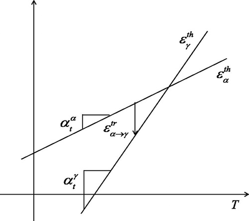
This term leads to shrinkage during the austenization when ferrite transforms to austenite. The case of two phases is illustrated in assuming constant thermal expansion for each phase. The shift between the curves gives the transformation strain due to phase change.
Figure 2. Possible representation of thermal expansion for mixture rules.
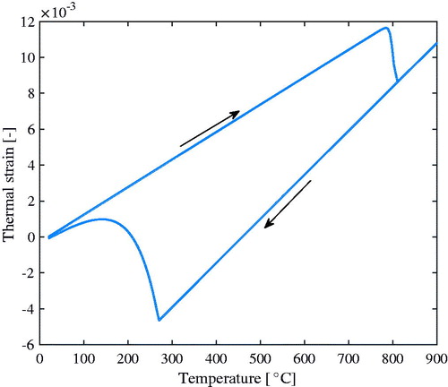
The above can be illustrated for a low alloy steel subject to a heating–cooling cycle going from room temperature up to 900 °C and then down again fast enough to generate a purely martensitic structure. The initial structure is an equilibrium fraction of perlite and ferrite shown in . The phase change model is described in [Citation8, Citation25] based on [Citation26, Citation27]. The corresponding computed thermal strains are shown in . The final increase in volume during cooling is due to martensite formation that starts around 280 °C.
Figure 3. Predicted phase changes during thermal cycle of AISI 4150 steel.
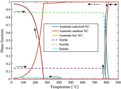
Figure 4. Predicted thermal strain for AISI 4150 due to thermal cycle.
Plasticity model
The effect of phase transformation on flow stress of materials is well known, particularly for steels, where various heat treatments are used to generate different microstructures and thereby changing their yield strength. Physics-based models or so-called mechanism-based plasticity models [Citation28]–[Citation31] are based on the underlying physics of the deformation that dominates under the relevant loading conditions. This kind of models has a natural handshake with respect to some microstructural information such as recrystallization [Citation32, Citation33], precipitates and solutes [Citation34]–[Citation39]. However, they are on the same ground as engineering type of models when determining macroscopic flow stress from a mixture of individual phases as well as whether hardening, that is, dislocation structure, is inherited or not during a phase change. Furthermore, same approaches for transformation induced plasticity are needed for physics-based as well as engineering type of models. The paper does not describe transformation induced plasticity models and the reader is referred to [Citation40]–[Citation44].
The basic mechanisms for plasticity and creep are the motion of dislocations and diffusion of atoms. These two phenomena do influence each other. The notation plasticity is used to denote processes where dislocation motion dominates. Creep is the used notation when diffusion of atoms (diffusional flow) dominates. The effect of phase changes may also be called a plastic deformation. However, they are included in transformation strains discussed in the previous chapter.
Frost and Ashby [Citation29, Citation45] describe a dislocation density-based model in terms of additive contributions to the total inelastic strain rate from various mechanisms. However, here, it is described as an addition of various contributions to the flow stress. The basic idea is that the flow stress is assumed to consist of contributions from long-range and short-range obstacles interacting with moving dislocations. The former are athermal [Citation46], meaning that thermal energy cannot help moving dislocation to overcome the deformed regions of the lattice. This long-range stress must be overcome by the applied stress before a dislocation can move. Thermal activated processes can assist the dislocation when overcoming short-range obstacles. The flow stress is written as
(12)
(12)
This additive decomposition is also assumed in [Citation32, Citation47–49]. The books [Citation35, Citation50, Citation51] and the papers by Kocks et al. [Citation31, Citation52, Citation53] give extensive descriptions of the approach. The current dislocation density-based plasticity model is built on the framework of Bergström [Citation54] and Estrin and Mecking [Citation55]. The formulation is based on the concept of a rate dependent yield surface. The commonly used von Mises yield criterion with the associated flow rule together with the consistency condition, that is, the stress state must stay on the yield surface, determine the amount of plastic strain. Notice that creep strain due to diffusional flow can occur even for stress states inside this yield surface. A general creep model is given in next chapter.
The long-range contributions is assumed to consist of two parts
(2)
(2)
is often called strain hardening and is due to the effect of forest dislocations parallel to the moving dislocations.
is the Hall–Petch, that is, grain size, contribution to the flow stress. They are described somewhat more in next chapter.
The effective stress, , equals the yield stress during plastic flow and EquationEq. (1)
(1)
(1) gives
(13)
(13)
It can be written as
(14)
(14)
Thus, the short-range stress is equal to the part of the applied stress that exceeds the long-range term and drives the dislocations. The short-range term due to different obstacles can be combined in various ways. There is a general model for obstacles, described later, and more specific models proposed for solutes and precipitates of various types. The latter are not described in the current paper. One example of a model for solutes is given in [Citation39] and for precipitates in [Citation36]. A general formula for how to combine the effect of obstacles with different strength [Citation34, Citation56–58] is
(15)
(15)
The simplest approach is to sum their contributions to the short-range term, that is k = 1.
The expression for the short range contribution depends on what mechanism is assumed to be rate controlling [Citation45].
The model deals only with two types of dislocation densities, mobile and immobile. However, only the later need to be computed explicitly. The mobile dislocations are, according to the Orowan equation [59], related to the effective plastic strain rate by
(17)
(17)
where
is the density of mobile dislocations, b is the magnitude of the Burgers vector and
is the average velocity of the dislocations. M is the Taylor lattice factor that relates the shear a dislocation causes in a slip plane to effective plastic strain rate [Citation60, Citation61]. It depends on the lattice and its deformation and is often taken as constant 3.06 for face-centered cubic lattice. The simplifications in a later chapter gives an explicit relation between plastic strain rate and immobile dislocations and therefore they need not be computed with an evolution equation like the immobile dislocation density.
Long-range contributions
The interactions between moving dislocations and immobile dislocations are of the long-range type if they are nearly parallel, else of a short-range type discussed in next section. The long-range interaction is the physical basis for what is called for strain hardening of a metal. It is written as
(18)
(18)
where α is a proportionality factor,
is the density of immobile dislocations and G is the temperature dependent shear modulus. The square root of the density of immobile dislocations is proportional to their average distance. This term requires evolution equations for the immobile dislocation density. The evolution equation for the dislocation density consists of hardening,
, and softening,
, contributions
(19)
(19)
These evolution equations are described in [Citation32, Citation39, Citation54].
It is assumed that the Hall–Petch term also is a long-range contribution as it affects the virgin yield limit of a material. It is due to pile-up of dislocations at grain boundaries leading to the activation of slip systems in neighboring grains [Citation62]. The contribution is typically given as
(20)
(20)
where g is the grain size. The coefficient
depends on the critical resolved shear stress of the material [Citation63] and thereby it depends on the shear modulus [Citation62]. The equation is rewritten as
(21)
(21)
in order to accommodate temperature dependency of this long-range contribution. G(T) is the shear modulus at the current temperature and GRT is the shear modulus at room temperature.
Short-range contribution
Frost and Ashby [Citation45] proposed that the mean velocity of mobile dislocations in EquationEq. (17)(17)
(17) when dislocation glide is dominating is given by
(22)
(22)
where
is the mean free path between two successful events, that is passed obstacles.
is the attempt frequency [Citation64, Citation65] with a value around 1010 and
is the energy barrier, or the activation energy, needed for overcoming the obstacle. kB is Boltzmann’s constant. A general formula for the activation energy, due to various obstacles [Citation53, Citation66, Citation67] is
(23)
(23)
The parameters and
are calibration parameters where some recommendations are given in [Citation45].
is the free energy required to overcome the obstacles without aid from external stress. There is an upper limit to the stress
in this expression. The quantity
is the athermal flow strength at which the applied stress can move the dislocation past the obstacle without aid of thermal energy. It reflects not only the strength but also the density and arrangement of the obstacles. The previous two equations can be inserted into EquationEq. (17)
(17)
(17) giving
(24)
(24)
Frost and Ashby [Citation45] recommend values around 106 for the reference rate . This equation shows how the short-range stress corresponds to a certain plastic strain rate as stated in the context of EquationEq. (14)
(14)
(14) . The equation can be rewritten as
(25)
(25)
If glide is dominating mechanism, that is, it requires the lowest stress for a given temperature and plastic strain rate, then this stress is taken as equal to the short-range stress, . There are other alternative mechanisms, see [Citation45], as temperature increases and diffusion assists the dislocation in overcoming obstacles, for example by glide plus climb.
Creep model
Creep gives an additional strain contribution to EquationEq. (1)(1)
(1) . A quite general creep model for creep [Citation45, Citation68–71] is
(26)
(26)
where m, n and Ac are calibration parameters and Deff is the effective diffusivity due to a combination of pipe, that is, along dislocations, grain boundary and lattice diffusions [Citation45], depending on what mechanisms contribute. Sometimes a threshold stress,
, is introduced by replacing
with
. The expression
equals
.
Example of flow stress for materials
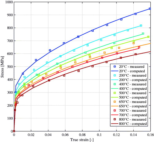
Babu and Lindgren [Citation32] calibrated a flow stress model for Ti-6Al-4V including the effect of globularization. Some examples of calibrated curves are shown in . Lindgren et al. [Citation39] calibrated a dislocation density based model for the austenitic stainless steel AISI 316 L and some curves are shown in . Calibration curves for Alloy 625 are shown in .
Figure 5. Calibrated flow stress of Ti-6Al-4V in flow softening region, adapted from [Citation32]. Lines with markers are experiments and solid lines are model results.
![Figure 5. Calibrated flow stress of Ti-6Al-4V in flow softening region, adapted from [Citation32]. Lines with markers are experiments and solid lines are model results.](/cms/asset/f13ae201-46b9-4bbe-9e3a-46250200246e/uths_a_1530965_f0005_c.jpg)
Figure 6. Calibration and validation case for flow stress of AISI 316L in high temperature region, adapted from [Citation39]. Symbols denote experimental results and solid lines are computed curves.
![Figure 6. Calibration and validation case for flow stress of AISI 316L in high temperature region, adapted from [Citation39]. Symbols denote experimental results and solid lines are computed curves.](/cms/asset/a087e3b5-0241-4486-8e91-e1c15f64679f/uths_a_1530965_f0006_c.jpg)
Figure 7. Measurements and model results for Alloy 625. Tests performed with a strain rate of 0.01 s−1.
Application of CWM to AM
The increase of the size of models that can be solved is mainly due to the hardware evolution of computers but also to software developments. Large models, measured as number of degrees of freedom multiplied by number of time steps in the finite element analysis, had reached about 108 around year 2000 [Citation4] and became 1010 around 2005 [Citation8]. The early [Citation4] CWM models were mainly plane models, plane stress or strain and axisymmetric cases. Then, (around 1980) even two-dimensional (2D) models of multipass welds required lumping techniques or other approaches in order to reduce their sizes. Later (around 1995), it was possible to model each pass individually [Citation72] even for a large number of weld passes. Dike et al. [Citation73] simulated a short 3 D weld consisting of four weld passes about the same time. Today, it is possible to simulate quite large multipass welds using 3 D models. However, history repeats itself, now the same strategies for efficient simulations are required when simulating AM [Citation10, Citation74, Citation75]. Both examples below demonstrate the use of the so-called lumping technique, which means that a number of layers are merged. Furthermore, each layer is laid instantaneously.
The Directed Energy Deposit (DED) technique builds up a structure by a kind of multipass welding. The filler material can be fed by wire or powder. Each layer is much thicker than in the case of Powder Bed Fusion (PBF) processes. However, for large structure, the computational time may become very large for DED processes and is still overwhelming in the case of PBF processes.
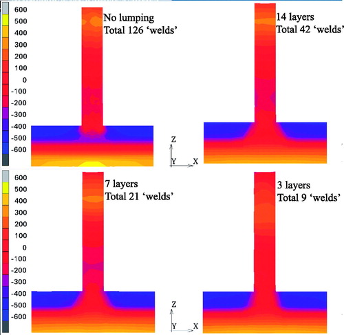
The DED process described in [Citation76] of Alloy 625 has been simulated, using a three-dimensional model, with various amount of lumping. The built plate, size 152.4 × 38.1 mm2, is fixed at one end. A 101.6 mm long wall made up of 42 layers with three beads across its width is built. Thus there is a total of 126 ‘welds’. The general rule is that larger ‘welds’ give larger deformations, as they are comparatively stronger compared to the stiffness of the existing material. Thus the lumping gives larger and fewer heating cycles as well as larger oscillations in the vertical deflection of the build plate (not shown here). The effect of the lumping on residual axial stress is shown in . The residual stresses are fairly stable for this range of lumping of layers despite that this is also combined with increasing size of elements. The finest model with no lumping has 43,313 hexahedron elements. The model where 14 layers are lumped into one layer giving a total of 3 layers giving 9 ‘welds’, has 3542 elements. One should note that there are no phase changes in the material. Phase changes lead do cyclic varying properties and give visible variations in the residual stresses and that will change with lumping.
Figure 8. Axial stress over a cross-section in the middle of the wall for various amount of lumping.
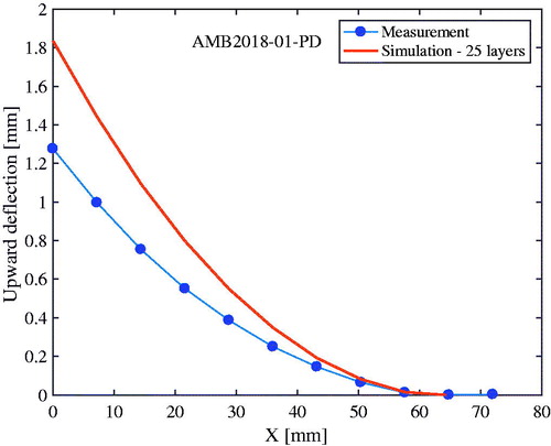
An example of PBF modeling is based on the AMB2018-01 ‘bridge’ structure made of Alloy 625 from NIST AM-Benchmark suite. The actual AM process consists of 600 layers lumped into 25 layers in the model. Furthermore, each layer is heated instantaneously in the PBF order to further speed up the simulation. The lateral deflection after cutting the build structure from the support plate can be in . It is clear that the residual stresses released when cutting the bridge from the built plate is considerably larger than in the model.
Figure 9. Computed and measured vertical deflection after cutting bridge from built plate.
Concluding remarks
The paper has highlighted some important issues for predicting thermal stresses, transient and residual stresses. Thermal stresses are of great practical interest not only in welding. They cannot be reduced by adding more or stronger material as the material is the driver for these stresses. Therefore, it is of great interest to predict them and enable redesign in order to reduce them. This holds particularly for welding applications where loose fixturing gives large deformations and a strong fixture gives large residual stresses. Predictive models give the possibility to precompensate the shape of a component or structure to reduce residual stresses and maintain fulfill tolerances. The increasing interest in CWM is probably due to its applicability to additive manufacturing where the same problem exists. The case in is an example where the computed results (not shown here) matches measured deformations in [Citation76] and the case in where they do not match well. One big difference between the two cases is the built temperature and time. The PBF process takes longer time and is performed in a chamber. Thus, there will likely be more recovery in the material in the PBF case that will reduce accumulated stresses and thereby the distortion upon cutting the bridge from the build plate. Thus, the deviation in is probably more dependent on the constitutive model than the effect of lumping.
Disclosure statement
No potential conflict of interest was reported by the authors.
Additional information
Funding
References
- wikipedia. “witold nowacki,” [online]. available: en.wikipedia.org/wiki/witold_nowacki
- B. Andersson, and L. Karlsson, “Thermal stresses in large butt-welded plates,” J. Therm. Stress., vol. 4, no. 3–4, pp. 491–500, 1981. DOI: 10.1080/01495738108909982.
- L. Karlsson, ‘Thermal stresses in welding,’ in Thermal Stresses I, R. B. Hetnarski, Ed., Amsterdam: Elsevier Science Publishers, 1986, pp. 300–389.
- L. E. Lindgren, “Finite element modeling and simulation OF welding part 1: increased complexity,” J. Therm. Stress., vol. 24, no. 2, pp. 141–192, Feb. 2001. DOI: 10.1080/01495730150500442.
- L. E. Lindgren, “Finite element modeling and simulation OF welding. Part 2: improved material modeling,” J. Therm. Stress., vol. 24, no. 3, pp. 195–231, Mar. 2001. DOI: 10.1080/014957301300006380.
- L. E. Lindgren, “Finite element modeling and simulation of welding. Part 3: efficiency and integration,” J. Therm. Stress., vol. 24, no. 4, pp. 305–334, Apr. 2001. DOI: 10.1080/01495730151078117.
- L. E. Lindgren, A. Lundbäck, and M. Fisk, “Thermo-mechanics and microstructure evolution in manufacturing simulations,” J. Therm. Stress., vol. 36, no. 6, pp. 564–588, Jun. 2013. DOI: 10.1080/01495739.2013.784121.
- L. E. Lindgren, Computational Welding Mechanics. Thermomechanical and Microstructural Simulations: Cambridge, England: Woodhead Publishing, 2007.
- J. N. Reddy, and C. D. Chin, “Thermomechanical analysis of functionally graded cylinders and plates,” J. Therm. Stress., vol. 21, no. 6, pp. 593–626, Jun. 1998. DOI: 10.1080/01495739808956165.
- L. E. Lindgren, and A. Lundbäck, “Approaches in computational welding mechanics applied to additive manufacturing: Review and outlook,” Comptes Rendus Mécanique, vol. 346, no. 11, pp. 1033–1042, Nov. 2018. DOI: 10.1016/j.crme.2018.08.004.
- A. L. Sutton, and W. Hume-Rothery, “The lattice spacings of solid solutions of titanium, vanadium, chromium, manganese, cobalt and nickel in α-iron,” Lond., Edinburgh, Dublin Philos. Mag. J. Sci., vol. 46, no. 383, pp. 1295–1309, Dec. 1955. DOI: 10.1080/14786441208521140.
- Z. Basinski, W. Hume-Rothery, and A. Sutton, “The lattice expansion of iron,” Proc. R. Soc. Lond. Ser. A. Math. Phys. Sci., vol. 229, no. 1179, pp. 459, May 1955. DOI: 10.1098/rspa.1955.0102.
- S. J. Lee, and K. D. Clarke, “A conversional model for austenite formation in hypereutectoid steels,” Metall. Mater. Trans. A, vol. 41, no. 12, pp. 3027–3031, Dec. 2010. DOI: 10.1007/s11661-010-0418-9.
- S. J. Lee, K. D. Clarke, and C. J. Van Tyne, “An on-Heating Dilation conversional model for austenite formation in hypoeutectoid steels,” Metall. Mater. Trans. A, vol. 41, no. 9, pp. 2224–2235, Sep. 2010. DOI: 10.1007/s11661-010-0267-6.
- W. C. Leslie, “Iron and its dilute substitutional solid solutions,” Metall. Trans., vol. 3, no. 1, pp. 5–26, Jan. 1972. DOI: 10.1007/BF02680580.
- J. M. Moyer, and G. S. Ansell, “The volume expansion accompanying the martensite transformation in iron-carbon alloys,” Metall. Trans. A., vol. 6, no. 9, pp. 1785, Sep. 1975. DOI: 10.1007/BF02642308.
- M. Onink et al., “The lattice parameters of austenite and ferrite in Fe-C alloys as functions of carbon concentration and temperature,” Scripta Metall. Mater., vol. 29, no. 8, pp. 1011–1016, Oct. 1993. DOI: 10.1016/0956-716X(93)90169-S.
- M. Schwenk, J. Hoffmeister, and V. Schulze, “Experimental validated residual stresses and distortion prediction for dual frequency induction hardening,” Int. J. Appl. Electromagn. Mech., vol. 44, no. 2, pp. 127–135, Feb. 2014. DOI: 10.3233/JAE-141752.
- W. Souder, and H. P. “Thermal expansion of a few steels,” Sci. Papers Bureau Standards, vol. 17, pp. 611–g26, 1922. DOI: 10.6028/nbsscipaper.120.
- M. R. Fellinger, L. G. Hector, and D. R. Trinkle, “Ab initio calculations of the lattice parameter and elastic stiffness coefficients of bcc Fe with solutes,” Comput. Mater. Sci., vol. 126, pp. 503–513, Jan. 2017. DOI: 10.1016/j.commatsci.2016.09.040.
- H. Zhang, B. Johansson, R. Ahuja, and L. Vitos, “First-principles study of solid-solution hardening in steel alloys,” Comput. Mater. Sci., vol. 55, pp. 269–272, Apr. 2012. DOI: 10.1016/j.commatsci.2011.12.020.
- H. Zhang, S. Lu, M. Zhou, M. P. J. Punkkinen, B. Johansson, and L. Vitos, “Ab initio determination of the elastic properties of ferromagnetic body-centered cubic Fe-Mn-Al alloys,” J. Appl. Phys., vol. 118, pp. 103904, Sep. 2015. DOI: 10.1063/1.4930162.
- H. Zhang, M. P. J. Punkkinen, B. Johansson, and L. Vitos, “Elastic parameters of paramagnetic iron-based alloys from first-principles calculations,” Phys. Rev. B, vol. 85, pp. 054107, Feb. 2012. DOI: 10.1103/PhysRevB.85.054107.
- S. J. Lee, M. Lusk, and Y.-K. Lee, “Conversional model of transformation strain to phase fraction in low alloy steels,” Acta Mater., vol. 55, pp. 875–882, Feb. 2007. DOI: 10.1016/j.actamat.2006.09.008.
- A. S. Oddy, J. M. J. McDill, and L. Karlsson, “Microstructural predictions including arbitrary thermal histories, reaustenization and carbon segregation effects,” Can. Metall. Quart., vol. 35, pp. 275–283, Jul. 1996. DOI: 10.1179/cmq.1996.35.3.275.
- C. Henwood, M. Bibby, J. Goldak, and D. Watt, “Coupled transient heat transfer - microstructure weld computations (Part B),” Acta Metall., vol. 36, no. 11, pp. 3037–3046, Nov. 1988. DOI: 10.1016/0001-6160(88)90186-1.
- D. Watt, L. Coon, J. Bibby, J. Goldak, and C. Henwood, “An algorithm for modelling microstructural development in weld heat-affected zones (Part A) reaction kinetics,” Acta Metall., vol. 36, no. 11, pp. 3029–3035, Nov. 1988. DOI: 10.1016/0001-6160(88)90185-X.
- Y. Estrin, “Dislocation-density related constitutive modeling,” in Unified Constitutive Laws of Plastic Deformation, A. S. Krausz and K. Krausz, Eds., San Diego: Academic Press, pp. 69–106, 1996.
- H. Frost, and M. Ashby, "Deformation-Mechanism Maps. The plasticity and creep of metals and ceramics," [Online]. Available: engineering.dartmouth.edu/defmech.
- H. Frost, and M. Ashby, “Deformation-mechanism maps for pure iron, two austenitic stainless steels and a low-alloy ferritic steel,” in Fundamental Aspects of Structural Alloy Design, R. I. Jaffee and B. A. Wilcox, Eds., Oxford, England: Plenum Press, pp. 26–65 1977.
- U. F. Kocks, and H. Mecking, “Physics and phenomenology of strain hardening: the FCC case,” Prog. Mater. Sci., vol. 48, no. 3, pp. 171–273, Mar. 2003. DOI: 10.1016/S0079-6425(02)00003-8.
- B. Babu, and L. E. Lindgren, “Dislocation density based model for plastic deformation and globularisation of Ti-6Al-4V,” Int. J. Plast., vol. 50, pp. 94–108, Nov. 2013. DOI: 10.1016/j.ijplas.2013.04.003.
- G. Engberg, and L. Lissel, “A physically based microstructure model for predicting the microstructural evolution of a C-Mn steel during and after hot deformation," Steel Res. Int., vol. 79, no. 1, pp. 47–58, Jan. 2008. DOI: 10.1002/srin.200806315.
- A. Ardell, “Precipitation hardening,” MTA, vol. 16, no. 12, pp. 2131–2165, Dec. 1985. DOI: 10.1007/BF02670416.
- D. Caillard, and J. L. Martin, Thermally Activated Mechanisms in Crystal Plasticity, vol. 8, Oxford: Pergamon, 2003.
- M. Fisk, J. C. Ion, and L. E. Lindgren, “Flow stress model for IN718 accounting for evolution of strengthening precipitates during thermal treatment,” Comput. Mater. Sci., vol. 82, pp. 531–539, Feb. 2014. DOI: 10.1016/j.commatsci.2013.10.007.
- R. L. Fleischer, “Substitutional solution hardening,” Acta Metall., vol. 11, no. 3, pp. 203–209, Mar. 1963. DOI: 10.1016/0001-6160(63)90213-X.
- R. L. Fleisher, “Solution hardening,” Acta Metall., vol. 9, no. 11, pp. 996–1000, Nov. 1961. DOI: 10.1016/0001-6160(61)90242-5.
- L. E. Lindgren, Q. Hao, and D. Wedberg, “Improved and simplified dislocation density based plasticity model for AISI 316 L,” Mech. Mater., vol. 108, pp. 68–76, May 2017. DOI: 10.1016/j.mechmat.2017.03.007.
- J. B. Leblond, “Mathematical modelling of transformation plasticity in steels II: Coupling with strain hardening phenomena,” Int. J. Plast., vol. 5, no. 6, pp. 573–591, Jun. 1989. DOI: 10.1016/0749-6419(89)90002-8.
- J. B. Leblond, J. Devaux, and J. C. Devaux, “Mathematical modelling of transformation plasticity in steels I: Case of ideal-plastic phases,” Int. J. Plast., vol. 5, no. 6, pp. 551–572, Jun. 1989. DOI: 10.1016/0749-6419(89)90001-6.
- L. Taleb, and S. Petit, “New investigations on transformation induced plasticity and its interaction with classical plasticity,” Int. J. Plast., vol. 22, no. 1, pp. 110–130, Jan. 2006. DOI: 10.1016/j.ijplas.2005.03.012.
- M. Wolff, M. Böhm, and B. Suhr, “Comparison of different approaches to transformation-induced plasticity in steel,” Materialwissenschaft Und Werkstofftechnik, vol. 40, no. 5–6, pp. 454–459, Jun. 2009. DOI: 10.1002/mawe.200900476.
- S. Yadegari, S. Turteltaub, and A. S. J. Suiker, “Coupled thermomechanical analysis of transformation-induced plasticity in multiphase steels,” Mech. Mater., vol. 53, pp. 1–14, Oct. 2012. DOI: 10.1016/j.mechmat.2012.05.002.
- H. Frost, and M. Ashby, Deformation-Mechanism Maps - The Plasticity and Creep of Metals and Ceramics, and, Oxford: Pergamon Press, 1982.
- H. Conrad, “The athermal component of the flow stress in crystalline solids,” Mater. Sci. Eng., vol. 6, no. 4, pp. 265–273, Oct. 1970. DOI: 10.1016/0025-5416(70)90054-6.
- L. E. Lindgren, B. Babu, C. Charles, and D. Wedberg, “Simulation of manufacturing chains and use of coupled microstructure and constitutive models,” in Presented at the International Symposium on Plasticity, St. Kitts, A. S. Khan and B. Farrokh, Eds., Fulton, Maryland: NEAT Press, 2010.
- L.-E. Lindgren, K. Domkin, and S. Hansson, “Dislocations, vacancies and solute diffusion in physical based plasticity model for AISI 316L,” Mech. Mater., vol. 40, no. 11, pp. 907–919, Nov. 2008. DOI: 10.1016/j.mechmat.2008.05.005.
- D. Wedberg, A. Svoboda, and L.-E. Lindgren, “Modelling high strain rate phenomena in metal cutting simulation,” Model. Simul. Mater. Sci. Eng., vol. 20, no. 8, pp. 085006, Oct. 2012. DOI: 10.1088/0965-0393/20/8/085006.
- U. Messerschmidt, Dislocation Dynamics during Plastic Deformation, Berlin: Springer, 2010.
- M. Shetty, Dislocations and Mechanical Behaviour of Materials, Delhi: PHI Learning, 2013.
- U. F. Kocks, “Kinetics of nonuniform deformation,” in Progress in Materials Science, J. Christian, P. Haasen, and T. Massalski, Eds., Oxford, England: Pergamon Press, 1981, pp. 185–241
- U. F. Kocks, A. S. Argon, and M. F. Ashby, Thermodynamics and Kinetics of Slip, and, vol.19, Oxford: Pergamon Press Ltd, 1975.
- Y. Bergström, “The plastic deformation of metals - A dislocation model and its applicability,” Rev. Powder Metall. Phys. Ceramics, vol. 265, pp. 79, 1983.
- Y. Estrin, and H. Mecking, “A unified phenomenological description of work-hardening and creep based on one-parameter models,” Acta Metall., vol. 32, no. 1, pp. 57–70, Jan. 1984. DOI: 10.1016/0001-6160(84)90202-5.
- A. de Vaucorbeil, W. J. Poole, and C. W. Sinclair, “The superposition of strengthening contributions in engineering alloys,” Mater. Sci. Eng.: A, vol. 582, pp. 147–154, Oct. 2013. DOI: 10.1016/j.msea.2013.06.032.
- J. C. Huang, and A. J. Ardell, “Addition rules and the contribution of [Delta]' precipitates to strengthening of aged Al—Li—Cu alloys,” Acta Metall., vol. 36, no. 11, pp. 2995–3006, Nov. 1988. DOI: 10.1016/0001-6160(88)90182-4.
- E. Nembach, and G. Neite, “Precipitation hardening of superalloys by ordered [gamma]'-particles,” Prog. Mater. Sci., vol. 29, no. 3, pp. 177–319, 1985. DOI: 10.1016/0079-6425(85)90001-5.
- E. Orowan, “Problems of plastic gliding,” Proc. Phys. Soc., vol. 52, no. 1, pp. 8, 1940. DOI: 10.1088/0959-5309/52/1/303.
- H. Mecking, U. F. Kocks, and C. Hartig, “Taylor factors in materials with many deformation modes,” Scripta Mater., vol. 35, no. 4, pp. 465–471, Aug. 1996. DOI: 10.1016/1359-6462(96)00137-6.
- G. Taylor, “Plastic strain in metals,” J. Inst. Metals, vol. 324, pp. 307, 1938.
- T. Johnston, and C. Feltner, “Grain size effects in the strain hardening of polycrystals,” Metall. Mater. Trans. B, vol. 1, no. 5, pp. 1161–1167, May 1970. DOI: 10.1007/BF02900226.
- N. Ono, R. Nowak, and S. Miura, “Effect of deformation temperature on Hall–Petch relationship registered for polycrystalline magnesium,” Mater. Lett., vol. 58, no. 1–2, pp. 39–43, Jan. 2004. DOI: 10.1016/S0167-577X(03)00410-5.
- P. Haasen, Physical Metallurgy, 3rd ed. Cambridge, England: Cambridge University Press, 1996.
- G. Schoeck, “Thermal activation in plastic deformation,” in Multiscale Phenomena in Plasticity: From Experiments to Phenomenology, Modelling and Materials Engineering, J. Lépinoux, D. Mazière, V. Pontikis, and G. Saada, Eds. Dordrecht, Netherlands: Kluwer Academic Publications, pp. 33–55, 2000.
- S. Nemat-Nasser, and W. G. Guo, “Thermomechanical response of HSLA-65 steel plates: experiments and modeling,” Mech. Mater., vol. 37, no. 2-3, pp. 379–405, Feb–Mar. 2005. DOI: 10.1016/j.mechmat.2003.08.017.
- V. Schulze, and O. Vöhringer, “Influence of alloying elements on the strain rate and temperature dependency of the flow stress of steels,” Metall. Mater. Trans. A, vol. 31, no. 13, pp. 825–830, Mar. 2000. DOI: 10.1007/s11661-000-1002-5.
- M. E. Kassner, and M. T. Pérez-Prado, “Five-power-law creep in single phase metals and alloys,” Prog. Mater. Sci., vol. 45, no. 1, pp. 1–102, Jan. 2000. DOI: 10.1016/S0079-6425(99)00006-7.
- F. Nabarro, and H. de Villiers, The Physics of Creep, London: Taylor & Francis, 1995.
- O. Sherby, and P. Burke, “Mechanical behavior of crystalline solids at elevated temperature,” in Progress in Materials Science, vol. 13, B. Chalmers and W. Hume-Rothery, Eds. Oxford: Pergamon Press, 1967, pp. 325–390.
- O. D. Sherby, and E. M. Taleff, “Influence of grain size, solute atoms and second-phase particles on creep behavior of polycrystalline solids,” Mater. Sci. Eng. A, vol. 322, no. 1–2, pp. 89–99, Jan. 2002. DOI: 10.1016/S0921-5093(01)01121-2.
- L.-E. Lindgren, H. Runnemalm, and M. O. Nässtrom, “Simulation of multipass welding of a thick plate,” Int. J. Numer. Methods Eng., vol. 44, no. 9, pp. 1301–1316, Mar. 1999. DOI: 10.1002/(SICI)1097-0207(19990330)44:9<1301::AID-NME479>3.0.CO;2-K.
- J. Dike, C. Cadden, R. Corderman, C. Schultz, and M. McAninch, “Finite element modeling of multipass GMA welds in steel plates,” in 4th International Conference on Trends in Welding Research, Gatlinburg, USA, pp. 57–66, 1995.
- L.-E. Lindgren, A. Lundbäck, M. Fisk, R. Pederson, and J. Andersson, “Simulation of additive manufacturing using coupled constitutive and microstructure models,” Addit. Manuf., vol. 12, Part B, pp. 144–158, Oct. 2016. DOI: 10.1016/j.addma.2016.05.005.
- J. Lindwall, A. Malmelöv, A. Lundbäck, and L. E. Lindgren, “Efficiency and accuracy in thermal simulation of powder bed fusion of bulk metallic glass,” JOM, vol. 70, no. 8, pp. 1598–1603, Aug. 2018. DOI: 10.1007/s11837-018-2919-8.
- E. R. Denlinger, J. C. Heigel, P. Michaleris, and T. A. Palmer, “Effect of inter-layer dwell time on distortion and residual stress in additive manufacturing of titanium and nickel alloys,” J. Mater. Proc. Technol., vol. 215, pp. 123–131, Jan. 2015. DOI: 10.1016/j.jmatprotec.2014.07.030.