
ABSTRACT
Purpose
The retrobulbar orbital vasculature is known to be complex and variable between individuals. This study aimed to produce a method to map the retrobulbar vessels, to generate 3D reconstructions, to visualise and to improve our understanding of their complexity.
Methods
Five human orbits donated under the Human Tissue Act (2004) were fixed in formalin, decalcified in 10% formic acid, and dehydrated in acetone at −20°C. Specimens were impregnated with epoxy resin, cured, and cut into 0.3 mm sections. Sections were stained with Gomori’s trichrome stain, imaged, and reconstructed using 3D reconstruction software (BioVis3D, version 3.1).
Results
The arterial system was reconstructed in all five specimens. The superior ophthalmic vein (SOV) and the central retinal vein (CRV) were reconstructed in four specimens. E12 sheet plastination showed excellent results for histological analysis at a macroscopic level; however, anatomical topology was not entirely preserved on a microscopic level. Gomori’s trichrome stain gave excellent results in highlighting axial sections of the arterial walls and their tunics, including finer calibre vessels, thus allowing detailed reconstruction of the arterial vasculature. Miller’s stain for elastin showed poor results in differentiating vessels from soft tissue; venous vasculature was poorly identified with both stains.
Conclusions
This study provided a detailed anatomical model of the retrobulbar orbital vascular system, a method that can be used for further studies to form a database relating to the topography of the arterial system. These models may be employed for teaching, and possible surgery planning, for both trainees and ophthalmic surgeons.
Introduction
The vascular anatomy of the orbit is of considerable clinical significance due to its importance in relation to disease pathology and treatment interventions affecting the orbit. Hayreh and DassCitation1,Citation2 gave a comprehensive description of the vascular anatomy of the orbit, providing a comprehensive analysis of the ophthalmic artery (OA), and noting the complex arrangement of the branches of the OA, with wide inter- and intra-individual variation.
In the majority of individuals, the dominant arterial supply to the orbit is by the ophthalmic artery. The artery can be divided into three major sections, with the most noted variations occurring in the second section, from the “angle” to where the artery either courses above the optic nerve (over 80%), to be situated medially to the ON, or crossing under (20%). The branching pattern following this section varies considerably; a single description or image cannot provide a full appreciation of the possible variants.Citation2
The venous drainage of the orbit shows less variability than the arterial supply; however, variations in the morphology of the inferior ophthalmic vein have led to some controversy over its existence, or whether the inferior system consists entirely of a plexus, drained either by the infraorbital vein or the middle ophthalmic vein.Citation3
Histological embedding using Biodur® epoxy E12 resin shows excellent results in preserving anatomical topology and morphology.Citation4 Its suitability for cutting thin sections for histological analysis at a macro- and microscopic level, staining, and reconstruction, has been demonstrated in reconstruction of the ethmoidal artery and other orbital structures.Citation5,Citation6 The method described by these researchers was followed for the epoxy embedding technique in this study. Rigidity of the resin once set allows for thin (2–4 mm) and ultrathin (<2 mm) sections to be cut, allowing for detailed anatomical analysis.Citation7
Construction of 3D models of the vascular system within the orbit enables better visualization and appreciation of the complex anatomy therein and may potentially be used for identifying safe surgical zones to approach the orbit and for virtual reality training for ophthalmic surgeons.
Materials and methods
Human orbits were obtained from soft-fixed cadavers donated to St. George’s, University of London, under the Human Tissue Act (2004), with consent for teaching and research. Five orbits from different donors (4 female, 1 male) with no known orbital pathology, were used in this study. The age range of the donors was 66–95 years.
Orbits were removed from the cadaver using a bandsaw, and trimmed with an oscillating saw, ensuring all four orbital walls remained undamaged. Excess soft tissue was dissected away from around the orbit. In order to reconstitute the natural contours of the globe, silicone was injected into the posterior chamber via the limbus, using a 60 ml syringe and a 16-gauge needle. This ensured that the eye resembled its natural contour in a living eye, and hence improved accuracy in reconstruction. The orbits were then fixed in 4% formalin for 24 hrs.
The orbits were decalcified at room temperature in twenty times their volume of 10% formic acid, until a 5% weight loss was noted, taking approximately 72 hrs. This produced an adequate reduction in bone density for sectioning, with minimal damage to the soft tissues.Citation6
The specimens were then dehydrated individually by placing them in ten times their volume of 100% acetone, pre-cooled to −20.0°C.Citation6 The specimens were stored in sealed containers at −20.0°C, and the acetone was changed every 48 hrs. Dehydration was terminated when acetone concentration stabilised above 99.5%, as measured with an acetonometer (Biodur Products GmbH, Heidelberg). This process took between 72 and 96 hrs. The specimens were then brought to room temperature and left to degrease in the same acetone bath at room temperature for a further 24 hrs, in order to enhance the optical qualities of the specimen.Citation7
A resin mixture consisting of Biodur® E12 resin, E6 hardener, and E600 accelerator (Biodur Products GmbH, Heidelberg) was made up in the ratio of 100:50:0.2 parts by weight.Citation4 The orbital specimens were removed from the acetone, placed into individual plastic containers and immersed in the resin mixture. These were then placed in a Heraeus VT 6130 M vacuum oven at 30°C for 24 hrs at atmospheric pressure, to allow the resin to equilibrate and begin to penetrate the specimen.
After 24 hrs, the pressure was reduced every hour to 550 Mbar (millibar), 425 Mbar, 320 Mbar and 210 Mbar for the subsequent 4 hrs, respectively, at 30°C. The temperature of the oven was then increased to 60°C, while the pressure was further decreased to 100 Mbar, and then to 25 Mbar for an hour each. At this point, orbits in the resin began to effervesce intensely due to reduced resin viscosity at higher temperatures, allowing for deeper penetration into the orbit.Citation6 The specimens were then left at 25 Mbar for a further 24 hrs until the bubbling ceased, indicating the end of forced impregnation.
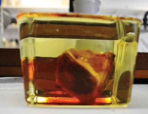
Specimens were then removed from the vacuum oven and placed in a clear plastic container filled with a fresh batch of the resin mixture. This was then placed in a standard laboratory oven at 65°C, for the curing process. Specimens were removed from the oven when complete polymerisation of the resin had been achieved and the resin had set hard (approximately 6 days), and left to cool at room temperature for a further 24 hrs ().
Figure 1. Orbit in epoxy resin block. Note the excellent optical qualities of the resin
Resin blocks were trimmed with a bandsaw to remove excess resin, then sectioned using a Buehler Isomet slow-speed diamond saw, with a 0.4 × 127 mm diamond blade, lubricated with Buehler ‘Cool 2ʹ lubricating fluid. Sections were cut at 0.7 mm intervals (obtaining 0.3 mm sections, with tissue loss of 0.4 mm due to blade thickness) in the coronal plane, from posterior to anterior. The sections were rinsed in distilled water and dried with a paper towel to remove saw residue and lubricating fluid. Sections were individually numbered with a pencil.
Following unsuccessful trials with Miller’s stain for elastin, and Weigert’s haematoxylin and eosin stain, a modified Gomori’s trichrome stain was used, using Wiegert’s haematoxylin in the staining process (Appendix I).
The stained sections were then mounted onto HiQaTM Supa Mega plain microscope slides with coverslips and glycerol. DPX mounting medium was initially trialled but was found to distort the sections, causing them to ripple. Soft-grip pegs were applied to the edges of the slides to compress the section and expel trapped air bubbles.
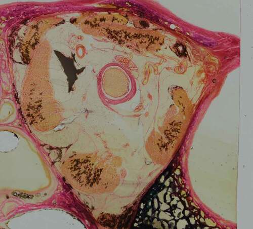
For imaging, slides were placed on a light source and photographed with a Nikon D3100 DSLR camera, fitted with a sigma 105 mm F2.8 macro lens, attached to a camera stand. The first section was photographed with a ruler for calibration. Images were then taken sequentially in order of section number. Images were uploaded and edited by Windows photo editor, for cropping and to optimise brightness ().
Figure 2. Coronal orbit section stained with modified Gomori’s trichrome stain with Wiegert’s haematoxylin
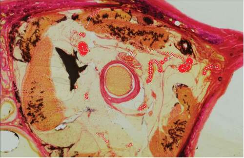
The edited images were imported into BioVis 3D (Version 3.1), a reconstruction software for serial histological sections.Citation8 All sections were aligned by superimposing the image onto the previous slice. Structures of interest (arterial/venous vasculature, optic nerve, globe of eye, extraocular muscles, and bony orbital walls) were manually traced () and then rendered into scaled 3-D models.
Figure 3. Sections were imported into BioVis 3D. Vessels were selected manually by observer, by adding nodes (red dots) to the relevant regions of interest
Results
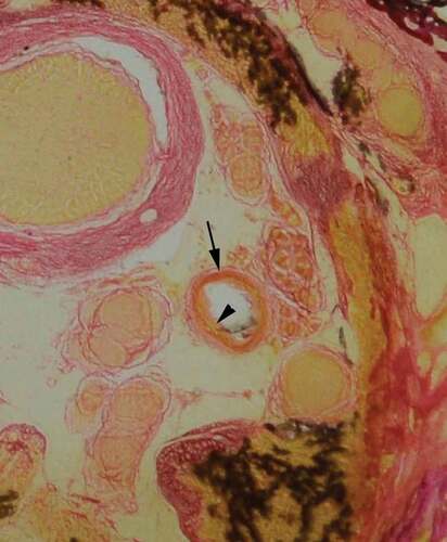
The staining process for vascular identification with Miller’s stain for elastin, as described by Adds and Al-RekabiCitation5 resulted in heavy background staining of the retrobulbar soft tissue. Weigert’s haematoxylin and eosin stain was trialled; however, this stained the background soft tissue light pink and did not provide good contrast to blood vessels for identification. A modified version of Gomori’s trichrome stain, using Weigert’s haematoxylin in the staining process, was found to give excellent contrast to the arterial vessels and the retrobulbar soft tissue. Furthermore, Gomori’s trichrome stain showed good differentiation of large arterial wall tunics, whereby the tunica adventitia stained a darker pink, and the tunica media a much lighter pink/orange hue ().
Figure 4. Identification of arterial wall tunics. Gomori’s trichrome stain, provided good differentiation, enabling identification of the tunica adventitia (arrow) and tunica media (arrowhead)
The background soft tissue of the retrobulbar region did not take up the stain, with the exception of the septae, thus enabling excellent identification of arterial vessels. The superior ophthalmic vein and central retinal vein were also identified; however, it was found to be more difficult to confidently identify some of the smaller calibre veins, hence giving a simplified 3-D reconstruction of the venous system. The 3D models subsequently generated can be manipulated to include or exclude certain anatomical structures of interest (), and can be rotated through 360° () and magnified ().
Figure 5. Arterial and venous system of the orbit in relation to the optic nerve (white) and extraocular muscles (gold)
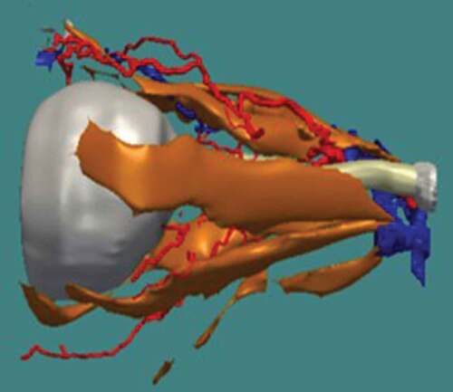
Figure 6. Three-D reconstruction of retrobulbar arterial system in relation to the optic nerve viewed from, (A) anterior, (B) posterior, (C) lateral, (D) medial, (E) superior, (F) inferior. Superior (S), inferior (I), anterior (A), posterior (P), medial (M), lateral (L)
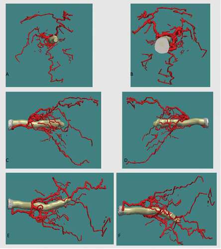
Figure 7. Three-D reconstruction the venous system in relation to the optic nerve viewed from (A) anterior, (B) posterior, (C) medial, (D) lateral, (E) superior, (F) inferior. Superior (S), inferior (I), anterior (A), posterior (P), medial (M), lateral (L)
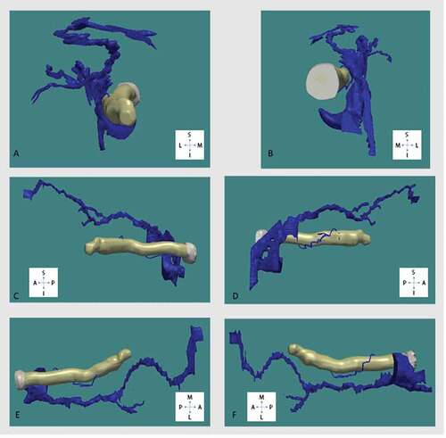
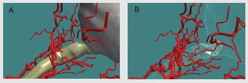
Figure 8. Three-D reconstruction of orbital arterial system, enlarged. The central retinal artery (arrowheads) can be seen piercing the optic nerve (A), and running within the optic nerve (B)
Discussion
Plastination with Biodur E12 epoxy resin mixture gave excellent results in the investigation of the cross-sectional anatomy of the orbital soft tissue structures, preserving the anatomical topology at a macroscopic level. It was found to be possible to map the topography of the orbital retrobulbar arterial vasculature in relation to the optic nerve, as well as other extra-ocular structures: the globe, extraocular muscles, and bony orbital walls (). The technique described here also enabled reconstruction of high-resolution models of the arterial vasculature, sampling at 0.7 mm intervals. It was, however, not possible to map the entire topography of the venous vasculature, except for the superior ophthalmic vein and central retinal vein, and their immediate tributaries. Nevertheless, the level of detail that was achieved in reconstructing the vascular system was greater than the basic information given in standard textbooks on the structure of the orbit and eye.Citation9,Citation10 However, since the sample size in this study was quite small (5 orbits), we would be reluctant to draw too many conclusions at this stage.
Gomori’s trichrome stain using Weigert’s haematoxylin demonstrated excellent results in clearly identifying and defining cross-sectional arterial vessels and their tunics, by direct staining of histological sections embedded in epoxy resin. The sections are also sufficiently robust to be handled safely and re-used for educational purposes.
In all orbits studied, there was a greater density of arteries proximal to the entry site of the central retinal artery, clustered around the ON, when comparing sections distal to this point. It was noted that the luminal diameters of the arteries proximally were appreciably larger in diameter than those arteries distally. It can therefore be inferred that, in all orbits, there is a noticeably greater density of arterial vasculature proximal to the CRA entering the ON than distal to this point. It was also noted that, further distal from this point of entry, there was a general decline in the number of arteries observed within the area of interest. These observations were in line with the findings of Bergen and Los,Citation11 that within the posterior retrobulbar region there is a greater arterial density, and from the middle to the anterior region of the orbit, the arterial density decreases.
The reconstructions of the venous system were limited to the SOV and CRV and their immediate tributaries. The course of the SOV was consistent within the retrobulbar region, and between orbits. In all orbits, there was a sharp turn where the SOV turned posteriorly towards the apex after coursing horizontally. Furthermore, it was observed that the SOV crossed over the optic nerve from medial to lateral, proximal to the coronal plane of the posterior pole of the globe. The anatomy of the SOV is potential of interest to neurosurgeons and ophthalmologists as a new way of treating carotid-cavernous fistula; typically, an endovascular approach through the internal jugular vein is used, but vascular access by means of the SOV could be used.Citation12
Information regarding the topography of the arterial vasculature is important for ophthalmic surgeons in identifying safe zones within the orbit for planning approaches for surgical access, in order to reduce iatrogenic events such as ARBH. This project aimed to begin building a database of the arterial system within the orbit, as there are significant variations between individuals.Citation1,Citation2 This database would provide a greater knowledge and appreciation of the topographical relations of the OA. While detailed analysis of the branching pattern is outside the scope of this study, these 3-D realisations can be used as a basis for further research.
Limitations
This study was limited to the analysis of five orbital specimens due to time limitations. Also, it proved not possible to visualise the fine branching pattern of the venous systems. A suitable histological stain for the lymphatic system could not be identified. Additionally, the formation of the vascular model may show some inter-observer variability, especially with the smaller calibre vessels, as the identification of structures of interest is operator-dependent.
Conclusion
This project provided a detailed anatomical model of the retrobulbar orbital arterial system and the major veins. While there are likely to be variations in the vasculature between individuals, this study provides the basis for establishing a database for the topography of the arterial system, which may be used for teaching and possible surgery planning, for both trainees and ophthalmic surgeons.
Acknowledgments
The authors wish to thank those who donated their bodies to science so that this research could be performed. These donors and their families deserve our highest gratitude.
Disclosure statement
The authors report no conflicts of interest. The authors alone are responsible for the content and writing of the article.
References
- Hayreh SS, Dass R. The ophthalmic artery: I. Origin and intra-cranial and intra-canalicular course. Brit J Ophthalmol. 1962;46(2):65–98. doi:10.1136/bjo.46.2.65.
- Hayreh SS, Dass R. The ophthalmic artery: III. Branches. Brit J Ophthalmol. 1962;46:212–247. doi:10.1136/bjo.46.4.212.
- Brismar J. Orbital phlebography. III. Topography of intraorbital veins. Acta Radiol. 1974;15(6): 577–594. http://www.ncbi.nlm.nih.gov/pubmed/4463695
- Sora M, Cook P. Epoxy plastination of biological tissue: E12 technique. J Int Soc Plast. 2007; 22:31–39. http://journal.plastination.org/archive/jp_vol.22/jp_vol.22_31-39.pdf. Accessed January 15, 2021
- Adds PJ, Al-Rekabi A. 3-D Reconstruction of the ethmoidal arteries of the medial orbital wall using Biodur® E12. J Plast. 2014; 26(2):5–10. http://journal.plastination.org/archive/jp_vol.26.2/JP_vol26.2_Dec2014_page5-10.pdf
- McCarthy P, Adds P, Uddin J, Gore S. 3-D reconstruction of the retrobulbar orbital septa using Biodur® E12. J Plast. 2017; 29:8–14. http://journal.plastination.org/archive/jp_vol.29.1/jp_vol.29.1_july17_pages8-14.pdf
- Ottone NE, Baptista CAC, Latorre R, Bianchi HF, Del Sol M, Fuentes R. E12 sheet plastination: techniques and applications. Clin Anat. 2018;31(5):742–756. doi:10.1002/ca.23008.
- BioVis3D (Version 3.1) [Computer program]. http://www.biovis3d.com/index.html. Accessed February 3, 2019.
- Zide BM, Jelks GW. Surgical Anatomy around the Orbit: The System of Zones. Philadelphia, PA: Lippincott Williams & Wilkins; 2012.
- Dutton JJ. Atlas of Clinical and Surgical Orbital Anatomy. 2nd ed. Philadelphia, PA: Elsevier Saunders; 2011.
- Bergen MP, Los JA vascular patterns in the human orbit in relation to the connective tissue septa. Proceedings of the 3rd International Symposium on Orbital Disorders; September 5–7, 1978; Amsterdam:197–201. doi: 10.1007/978-94-009-9978-7_34. Accessed February 3, 2021.
- Reis CVC, Gonzalez FL, Zabramski JM, Hassan A, Deshmukh P, Albuquerque FC, et al. Anatomy of the superior ophthalmic vein approach for direct endovascular access to vascular lesions of the orbit and cavernous sinus. Oper Neurosurgy. 2009;64(suppl_5):316–323. doi:10.1227/01.NEU.0000340781.34122.A2.