Abstract
A mathematical model for metal-coating delamination of degrading metal was developed incorporating multiple variable environmental and physical parameters. Metal-coating delamination not only depends on the electrochemical reactions at metal-coating interface but also on the factors like the type of propagating metal ions and their varying concentration with annual weather changes (summer and winter), time of exposure of the coated objects, type of coated objects, i.e. stationary or mobile vehicles and frequency with which certain vehicles are operating in various environments, e.g. controlled or uncontrolled in terms of environmental conditions. A cutting edge model has been developed to calculate the varying environmental conditions using iteration algorithm, time dependent uncertain position of objects like vehicle in various environments (controlled and uncontrolled) using stochastic approach, effect of seasonal changes (summer and winter) on ionic compounds concentration using algebraic method and instantaneous failure probability due to varying conditions. Based on the developed model, a detailed simulation study was conducted to investigate the metal-coating delamination process and the ways to regress the under coating metal corrosion.
Nomenclature
Unless otherwise specified, the following nomenclature is used in this paper.
Table
1. Introduction
Automotive industry and many architectural/engineering structures are protected from corrosion attack using various polymers for metal-coatings. There can be many types of coatings depending upon the application like organic coatings, non-stick coatings, chemically resistant coatings, thermal spray coatings and corrosion-resistant coatings.[Citation1] All such kinds of coatings improve the surface properties of metals/alloys such as adhesion, substrate degradation resistance, deformity resistance and scratch resistance. The organic coating protects the substrate by forming a physical barrier between substrate and the atmosphere, protecting it against varying environmental conditions. Despite this fact, unpredictable harsh environmental conditions may create circumstances which may lead to moisture, oxygen and other hygroscopic bodies to diffuse in to the coat causing certain inactive metal sites to become electrochemically active.[Citation2] This electrochemically active site, if exposed to the environment, results in the under-paint substrate to become cathodic which leads to the start of cathodic reactions beneath the coated surface resulting in delamination due to weakening in the coat-substrate bonding. Research studies reveal that hygroscopic species and certain water-soluble salts (ionic compound) play a key role in the bond-breaking reaction. Ogle [Citation3] investigated the relationship between the rate of coat delamination and the anodic/cathodic current density under the paint for zinc polymer system using a special electrochemical cell and came up with the solution to evacuate the under-paint surface from certain alkaline electrolytic species.[Citation4,5]
Stratmann [Citation6–12] investigated the delamination of the coating in the defected area using various experimental techniques. Startmann further investigated the delamination resulting due to weak bonding in partially damaged zones and compared these results with the reaction in the inactive sites.[Citation10–12] Experimental finding by Startmann indicated that after the activation of certain electrochemical sites, the metal-coating behaves like a jelly medium, which results in the weakening of metal-coating bonding and concluded that the driving factor for the coat delamination is the diffusion of ions from the defected zone to the metal end and the delamination rate depends upon the ionic strength and their diffusion rate.
A mathematical model was first developed by Allahar [Citation13]. The model employed porosity and the polarization kinetics to be dependent upon the pH which provided an adequate approach towards the bond-breaking phenomenon of metal-coating interface. Their research work provided a bridge between experimental data by Stratmann and the analytical modelling. Huang [Citation2] followed Allahar approach and designed an algorithm which investigated that the OH– ions along the metal-coating interface decide the propagation of front end of the delaminated coat, and the porosity depends upon the metal-coating bonding reaction. When the time constant associated with breaking bonds is small, the movement of the two fronts are close when compared to that of the diffusion and migration processes.[Citation2] Recently, numerical models were developed for mesomechanics.[Citation14–18] Mesomechanics seeks to relate material microstructure and its influence on macro responses on the constitutive basis. Current research contributes to mesomechanics approach through an enhanced modelling of the environmental implications while incorporating the uncertainty in deploying large vehicles in controlled and uncontrolled environments. The frequency of use of vehicles in terms of various environmental exposures with respect to time has also been modelled. The significant contribution of the current research is the incorporation of ionic transport at the interface and their relation to weakening the interfacial bonding plus the indeterminate position of vehicles has been analysed, and the predictive model has been developed.
The purpose of this research work was to develop a mathematical model for the metal-coating delamination considering all the environmental parameters necessary to be modelled that had not been previously considered. Literature survey shows that conventionally the focus of research was to design an analytical model, based on metal-coating bond degradation considering the only parameter i.e. pH.[Citation2,13] However, the diffusion of hygroscopic bodies also depends upon factors like temperature (T), relative humidity RH, salt concentration , type of salt (ionic compound) which diffuse towards the front end after delamination and also the standard diffusion rate for ionic specie. Other important parameters (not discussed in literature) that need attention are: The type of application (automobile, bridge, etc.) for which metal-coating delamination model is designed e.g. the analytical model for automobiles will consider different approaches compared to the one for stationary objects like bridges. The frequency of use of the vehicle in controlled (inside shed) and uncontrolled environments (open air) will decide the metal-coating delamination which requires stochastic approach. The approach enables to model the variable positions of the vehicle (controlled and uncontrolled) and the annual weather conditions (summer and winter) in which the vehicle is operated. All these parameters play a vital role in determining the instantaneous failure probability of metal-coating interface due to delamination.
2. Analysis of metal-coating delamination of two large vehicles
This research focuses on the development of novel modelling technique to predict metal-coating failure mechanism through delamination depending upon various environmental and physical parameters. Environmental parameters include seasonal weather (summer and winter) and concentration of salts in air (airborne salinity), while physical parameters include temperature T, relative humidity (RH) and time of exposure to any environment (t). The study reported in this section (Section 2) includes the collection of data from samples, taken from a stationary and operating large vehicles (tank) at the Tank museum, Bovington UK.[Citation19–23] A similar study by our research group has been performed previously and published in [Citation19–23].
This paper reports an enhanced model incorporating diffusion of different types of hygroscopic salts through delaminated metal coats. This factor was not built in our previous reported model [Citation24] which considered only two parameters i.e. temperature (T) and relative humidly (RH). The concentration of salts accumulated over coating’s surface (vehicle’s body) depends on vehicle’s position i.e. position in controlled environment (inside shed) or uncontrolled environment (open air) and upon its uncertain in–out movements. Also, the concentration of accumulated salts depends on the type of annual season (summer or winter) in which the vehicle is operated.
Inside the Tank museum (controlled environment), the temperature is kept between (18–25 °C) and RH is maintained at 40% throughout the year. However, outside (uncontrolled environment), the temperature can go as low as 0 °C during winter and as high as 30 °C during summer. Museum is located approximately 9 km north of the Atlantic Ocean/English channel. There is significant precipitation in this area, where fog, rain and/or snow are reported, on average, for 18 days of each month.[Citation25] Operating vehicle is used with a frequency of 3–6 round trips (in–out) per month. However, stationary vehicle is preserved inside the tank museum without any kind of operation. Both the vehicles (stationary and operating) were painted at the same time with the same coating type and the under same conditions.
Surface and sub-surface analyses for the samples from two large vehicles, in operation and stationary conditions, respectively, were performed using SEM and EDS. These results were compared and analysed, and based on the conclusion from these results, a novel mathematical model has been designed.
2.1. Analysis of samples from stationary vehicle
SEM and EDS were performed on the samples from vehicle stationed and preserved inside the museum. Results of three spectra (EDS points) are provided in Table (front face images). At all the three spectra, % wt. concentration of ionic species (O, Al, Si and Na) was less when compared to the vehicle in operation. No signs of coating degradation and delamination were found on all the samples. However, spectra 1, 2 and 3 showed that Fe was slightly oxidized due to the presence of O in bulk quantity on the front face surface. The identification of Al could be attributed to Al-based paints and coatings applied on the vehicle’s body. However, traces of Al were also found on the operating vehicle with equal average concentration.
Table 1. Showing SEM and EDS images (front face images and cross-sectional images) of samples taken from stationary and operating vehicles.
Cross-sectional images using SEM revealed % wt. concentration of ionic species along the interface and corrosion propagation of approximately 50 μm into the sub-surface as shown in Table (cross-sectional images). However, the coating was found to be intact with the substrate. Results of spectrum 1 showed small concentration of O but the concentration of other ionic species (Al and Si) was found to be negligible with no concentration of Na. Spectrum 2 (deep inside the interface), however, showed Fe (98.98 wt %) with very small concentration of O and rest (Al, Si and Na) as zero.
2.2. Analysis of samples from operating vehicle
SEM micrograph showed that these surfaces were corroding due to severe corrosion and delamination of surface-protective coating as shown in Table . EDS was performed on sample face at three separate points represented as spectra 1, 2 and 3 as shown in Table (front face images). On the front face, along the corroding surface, all three spectra, of which results are shown in Table , indicated that corrosion products comprised of FeO. In spectra 1, 2 and 3, the high proportion of O, nearly equal to Fe, can be attributed to coating delamination.
Further, cross-sectional investigation of coating–substrate interface revealed that corrosion propogated to almost the depth of 110 μm at the interface. For comparison, two spectrum points were analysed, showing different proportions of O, Al, Si and Na as shown in Table (cross-sectional images).
Table shows the delamination and corrosion propagation which could eventually lead to structural failure if under critical stress. In Table (cross-sectional images), spectrum 1 shows the presence of high amount of oxygen which illustrates the reason for the formation of FeO (corrosion) products at the interface of metal and coat, while Na ingress in metal coat is due to the presence of Na in atmospheric and sea salts. Spectrum 2, which is deep inside the metal-coating interface, shows little signs of Na and other species, however, O (which is the main corrosion ingredient) is still available in bulk quantity but less, compared to Spectrum 1. EDS results showed the presence of high ratio of Si which could be attributed to the working environment of operating vehicle.
2.3. Comparison of results from two vehicles and conclusion
The constant use of operating vehicle in controlled and uncontrolled environments under changing weather conditions (summer and winter) is the reason for high concentration of ionic compound deposition on vehicle’s body. Ionic specie like Na (in this case) causes alkaline behaviour of solution. Alkalinity can increase the pH which makes the electrolytic solution more basic, which, in turn, accelerates the cathodic delamination process. The high concentration of Na along with high water vapour and oxygen concentration, in case of samples from operating vehicle, caused a severe delamination. Atmospheric oxygen due to excess of water vapour, upon reduction produced OH– and accelerated cathodic delamination. Inside the delaminated region, Na acts as cation, while OH– ions act as majority anions.
Na was absent in case of samples from the stationary vehicle and, hence, no delamination was found despite the fact that sample had considerable defects on the coat. However, due to the absence of alkaline ionic specie (Na), the defects did not result in delamination of coating.
3. Modelling methodology
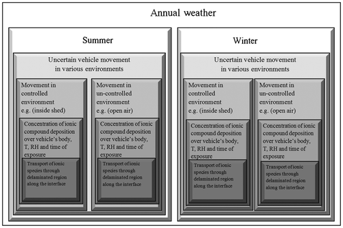
Metal-coating delamination due to under-coating metal corrosion is a complex process. It needs to be investigated from multidimensions, as for a vehicle in operation, large numbers of uncertain parameters take part in the delamination process. The developed model follows the methodology given in Figure .
Each box in Figure represents a distinct parameter which encapsulates further parameters, represented in the form of boxes. Annual weather is the outermost parameter, while transport of ionic species through defect along the interface (delaminated region) is the innermost parameter. Each inner parameter value depends on the outer parameter value. For example, transport of ionic species through defect along the interface depends on the concentration of ionic compound deposition on vehicle’s body (Se(t)), temperature (T), relative humidity (RH) and time of exposure (t). Similarly, the parameters: Se(t), T, RH and t depend on vehicle use in either controlled or uncontrolled environment. Likewise, the movement (operation or use) of vehicle in any environment (controlled or uncontrolled) can be uncertain. All these parameters, which finally decide the delamination rate, at the top, depend on annual weather i.e. summer or winter. Experimental study conducted in Tank Museum [Citation19–23] showed that during winter, the concentration levels of ionic compound deposited on vehicle’s body were recorded to be high but investigations show that diffusion rate is low and, similarly, the opposite case was noted for summer. Separate mathematical equations have been designed for each parameter, but are interdependent to give a shape of holistic design.
Based on the above methodology, a holistic model has been designed addressing all the issues which are absent in the previous models as discussed in Section 1.
4. Modelling annual weather variability and uncertain vehicle movement
The developed model takes into account the uncertain position of vehicle in variable environments (controlled and uncontrolled) incorporating annual weather variability (summer and winter). The parameters (uncertain position of vehicle and annual weather variability) play a vital role in metal-coating delamination, as vehicle movement is uncertain. Stochastic approach was used to model uncertain position and was related with the changing weather. Weather decides the concentration of ionic compound deposition over metal coat (vehicles body). However, diffusion of these metal ions through delaminated/defected zone of coating depends upon temperature (T), relative humidity (RH) and time of exposure t. The model was precisely built taking into account all such observations. A detailed simulation study was performed and results were deeply analysed.
4.1. Model for annual weather variability
It is notable that the propagation rate of metal ions (formed due to dissociation of ionic compound) inside the defected coating changes as a function of environmental conditions (weather) which in turn is a function of vehicle position (controlled or uncontrolled). Experimental results [Citation26–28] showed that hot weather constitutes lower ionic compound concentration (below average) at the surface of vehicle’s body compared to the cold weather expressed as,(1)
where is the maximum ionic compound concentration corresponding to the winter,
is the minimum ionic compound concentration corresponding to summer and
is the average ionic compound concentration corresponding to both the seasons. Equation (1) is schematically represented in Figure (a). The schematic is built on the original experimental data collected by Willison [Citation27] as shown in Figure (b)
Figure 2. (a) Schematic showing annual variation in ionic compound concentration for various seasons; (b) Experimental data collected for annual variation in various ionic compound concentrations (μg/m3) for a whole year.[Citation24]
![Figure 2. (a) Schematic showing annual variation in ionic compound concentration for various seasons; (b) Experimental data collected for annual variation in various ionic compound concentrations (μg/m3) for a whole year.[Citation24]](/cms/asset/2f814b24-6442-45fa-8ab2-75a876854b05/tast_a_990200_f0002_b.gif)
Schematic in Figure (a) depicts the concentration of ionic compounds (Na, Ca, Cs and Li) after 12 months of exposure for two different seasons (summer and winter). From the experimental investigation for annual environmental variation of various ionic compounds concentration by Willison [Citation27], it was reported that in the month of June (middle of spring), the ionic compounds’ concentration is minimum and in the month of January (middle of winter), the ionic compounds’ concentration is maximum
as shown in Figure (b). However, the ionic compounds diffusivity at the metal-coating interface is more prominent during spring to summer compared to the other seasons because of high temperature and humidity (metal ion diffusion through defect in coating will be modelled in Section 5).
4.2. Model for uncertain vehicle movement
This part of modelling is specifically developed considering the uncertain use of large vehicle in controlled and uncontrolled environments. The variable parameters used during the development of model are completely derived from the data collected using analysis of samples taken from vehicles (stationary and operating).
In this section, we will model the uncertain use of vehicles in controlled and uncontrolled environments. In controlled environment (e.g. inside the shed), parameters i.e. T, RH and are controlled, while in uncontrolled environment (e.g. in an open air), the parameters are not under control, meaning, making it an uncontrolled environment.
Daily use of vehicles is inherently uncertain and, thus, the impact of uncertain use on parameters (T, RH and ) needs to be addressed. This section uses stochastic modelling to quantify the uncertainties in the environment (controlled and uncontrolled) in which vehicle is used. The probability of vehicle used in controlled environment is pc for the total number of N times use in various environments and is expressed by probability mass function (PMF).
(2)
where will give the probability of using vehicle in controlled environment c out of total N uses in various environments (controlled and uncontrolled); c is the number of times the vehicle is used in controlled environment; N-c is the number of times the vehicle is used in uncontrolled environment (uc); x is the random variable defining the probability of getting exactly c times the vehicle use in controlled environment out of total N uses.
(3)
In Equation (2), depicts the binomial coefficient value
as given in Equation (3). The probability for the vehicle used in controlled environment can occur anywhere among total N times use and there are
ways of distributing c uses among total N uses of vehicle in controlled and uncontrolled environments.
The function calculates the probability of vehicle use in controlled environment with precision, if sufficient actual data regarding initial probability of use in controlled environment p is already known through constant observation (using videotaping or data logging). At least, the observation data for one day use of vehicle is required for the condition if the frequency of use of vehicle in one day is the same for all other days of a month. Similarly, at least a month’s observation data is required for the condition if the frequency of use of vehicle in one month is the same for all other months of a year. Similarly, at least one-year data is required if the frequency of the use of vehicle in one year is the same for all the coming years of its operation.
To understand the algorithm in Figure , consider an example: This year in the month of Jan., the recorded observation for initial probability p of vehicle used in controlled environment was 0.4. The crew reported that the use of vehicle is the same for every other year. For the coming year in Jan., it is now possible to forecast the use of vehicle using recorded value of p even if total use of vehicle N changes. Assume N = 6, iterating c (i = 1–6) and finding maximum value out of all values of function using
as shown in Table . The iteration value ‘i = c = 2’ against
gives the maximum number of times the vehicle is used in controlled environment (c = 2) out total N = 6. c is represented as the base, while uc is represented as the peak in Figure shown in Table .
Figure 3. Algorithm for calculating number of times the vehicle is used in controlled environment ‘c’ for a given probability ‘p’ among N applications.
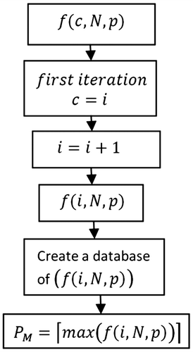
Table 2. Example to illustrate the number of times vehicle is used in controlled environment, c out of N time use.
4.3. Influence of uncertain vehicle movement and weather variability over ionic compound concentration on vehicles body (Combined model)
From Figure , it is evident that the shape of ionic compound concentration profile depends upon the weather (summer and winter). However, when considering the uncertain position of exposure (movement) of vehicle and the frequency with which the vehicle encounters the particular environment in Figure , ionic compound concentration on vehicle’s body becomes a function of its position (controlled and uncontrolled) and weather (summer and winter). Figure (combined model) shows the ionic compound deposition on vehicle body against vehicle position under various weather conditions (summer and winter). The vehicle can be operated both in controlled (c) and uncontrolled (uc) environment in any part of the season (summer and winter) as shown in Figure .
Figure 4. Annual variation in ionic compound deposition over vehicle coating depending upon vehicle position and seasonal conditions.
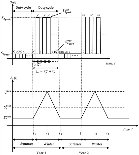
With reference to Figure , during the winter season, ionic compound concentration deposited on vehicle’s body depends upon the vehicle position, as during winter season, concentration of ionic compound in environment is high. For position in the controlled environment, minimum ionic compound concentration will be used. However, upon its position in uncontrolled environment, maximum ionic compound concentration
will be used. Where
and
are the average values for distinct peak and base values for ionic compound concentration, respectively, given as,
(4)
(5)
where represents the high concentration (peak) of ionic compound accumulated on the vehicle’s body during one-time operation in uncontrolled environment (uc) and
is the average concentration value of total n time operation in uncontrolled environment as shown in Equation (4). Likewise,
represents the low concentration (base) of ionic compound accumulated on the vehicle’s body during one-time operation in controlled environment (c) and
is the average concentration value of total n time use in controlled environment as shown in Equation (5).
4.3.1. Uncertain movement of vehicle in winter
The concentration of ionic compound accumulated on vehicle’s body during winter season also depends on total time for which vehicle is used in controlled and uncontrolled environments. The time of use of vehicle is represented by the pulse width of peak and base. Thus, the concept of duty cycle is introduced, incorporating total ionic compound concentration , which is given as,
(6)
where is the sum of all the concentration values
and
for n peaks and bases, respectively, and represents the total concentration of ionic compound accumulated during winter season as,
(7)
The purpose of introducing the duty cycle concept is due to the fact that time of use of vehicle (width of pulse) in any type of environment (controlled and uncontrolled) can vary. So, duty cycle calculates the percentage of the total time for which the vehicle is used in controlled or uncontrolled environment, and is given as,(8)
where and
show the total time interval for which the vehicle is used in uncontrolled and controlled environments respectively, while from Figure ,
and
show the time interval for only one pulse for uncontrolled and controlled environments, respectively, thus,
(9)
(10)
In case of Equation (6), duty cycle calculates the percentage of the total time vehicle used in uncontrolled environment which is multiplied by . This gives the concentration of ionic compound accumulated on vehicles body when operated in uncontrolled environment during winter season.
Similarly, when vehicle is operated in controlled environment, Equation (11) will be considered(11)
(12)
Thus, during the winter season, the total ionic compound concentration accumulated on the vehicle’s body will be the sum of and
,
(13)
4.3.2. Uncertain movement of vehicle in summer
During the use of vehicle in summer, the ionic compound concentration on vehicle’s body remains to the minimum level irrespective of whether it is applied to the controlled or un-controlled environment. The reason for minimum level is that during winter season, concentration of ionic compound in environment is low.
Same set of Equations (6)–(13) will be modified for summer,
(14)
where(15)
And for the controlled environment,
(16)
where
(17)
Thus, during the summer season, the total ionic compound concentration on vehicle surface will be,
(18)
4.3.3. Uncertain movement of vehicle during whole year (winter and summer)
For the annual accumulation of ionic compound concentration (μg/m3) on vehicle, the following equation (sum of Equations (13) and (18)) is used,
(19)
5. Modelling transport of metal ions through defect in coating on vehicle’s body
Uncertain vehicle movement and annual weather variability decide the concentration of ionic compound deposition over metal-coating on vehicle’s body. However, diffusion of these metal ions through delaminated/defected zone in coating depends upon temperature (T), relative humidity (RH) and time of exposure (t). The analytical model for metal ion transport through defected metal-coating, tied to the parameter i.e. concentration of ionic specie , allows the understanding of ionic diffusion mechanism at the interface which is dependent on T, RH and t. Where
has been derived in Equation (19). This section focuses on the design of model in order to illustrate metal ion diffusion in delaminated porous medium under time-dependent variation of T, RH, t and
.
Metal loss rate due to metal-coating delamination is directly related to the local current density (corrosion current density)
, when the surface is exposed to environmental effects (T, RH, t and
). The higher the current density, the higher the metal loss rate which can be written as,
(20)
The model in this section accounts for transport of water-soluble ionic specie in delaminated region. The ionic species deposited on vehicle’s body has been modelled in the previous sections. The analysis in Section 2 shows that the penetrating specie (alkaline compound), diffusing oxygen through pores, varying environment (seasonal changes) and uncertain vehicle movement are the factors that contribute towards the metal-coating delamination. Figure shows the mass transport of metal ions through defected coating. These metal ions diffuse through delaminated porous medium and head towards the front and intact regions of metal-coating interface. All the metal ion types discussed in Section 2 are the basic constituents of the ionic compound (having concentration ) which are present on the coating surface of the vehicle. The ionic compound dissociates/separates or splits into smaller particles, ions or radicals as a result of electrochemical reaction at the metal-coating interface.
Figure 5. Schematic representation of metal-coating delamination drawn from image taken from sample of operating vehicle using SEM (right of Figure 5). The metal is exposed to atmosphere through delaminated zone because of coating defect which provides an inlet to the external environmental pollutants. Downward figure shows the schematic for the decline of porosity through various stages.
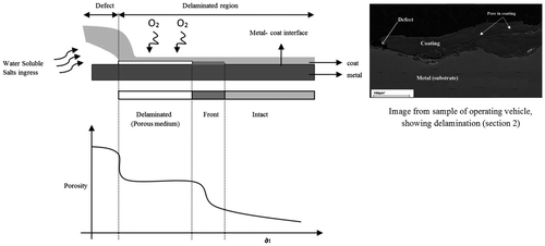
It is assumed that the porosity of delaminated, front and intact regions follow the non-linear sigmoid curve as shown in Figure .
The analytical model in Section 5.1 is analysed under the simplifying assumption: Only diffusion determines the transport of metal ions towards metal-coating interface. The effects of migration and convection are not considered.
Ionic transport rate through the defected surface at the front end of metal-coating interface decides the rate of metal loss, so these two parameters can be related using Equation (21)
(21)
where denotes the transport rate of metal ions through delaminated metal-coating interface, respectively. The corrosion rate cr(t) will be the function of four parameters: temperature (T), relative humidity (RH), time of exposure (t) and ionic compound concentration (
) which can be written as,
(22)
where K is the constant of proportionality and is called metal-coating degradation parameter. The higher the transport of external alkaline species through the defected coating, the higher will be the rate of delamination due to adhesion-loss and under-coating corrosion which will eventually result in structural failure under high stress.
5.1. Analytical model
The metal ion penetration process is a combination of diffusion, migration and convection. To account for these mechanisms, Equation (23) is used which is a combination of the diffusion migration and convection (advection) equations.[Citation26](23)
where is the effective average metal ions diffusion coefficient,
is the concentration of each ionic compound (1…n) which dissociates along the interface (free metal ions),
represents the solution potential and Jm is the electrolyte flux. RS and SS account for rate of homogeneous reaction and rate of production per unit volume by electrochemical reactions, respectively. The effect of homogeneous reaction was neglected. RS decides the pH for various regions based on oxygen reduction reaction. The electrochemical reaction decides the metal-coating adhesion strength. The effective average ionic diffusion coefficient is dependent upon the temperature (T), pore relative humidity (RH) and time of exposure (t) and is equated by finding
using
measured for metal ions at standard conditions.
in Equation (23) can be written as,
(24)
Equation (24) depicts the effective average metal ion diffusion coefficient value for all water-soluble ions that result due to the dissociation of ionic compounds which penetrate through defected region and enter the delaminated zone. The diffusion coefficient of ionic species for the porous medium is two orders of magnitude smaller than in aqueous medium.[Citation13] The function accounts for the diffusion rate of cations inside the delaminated zone. As cations along the metal–polymer interface seem to determine the rate of the delamination reaction, the effect of anions is negligible as OH– ions formed as a result of oxygen reduction account for the majority of anions population eliminating the effect of other anions in electrolyte solution. From Equation (24), F1(T), F2(RH) and F3(t) are correction expressions for temperature, humidity and ageing, respectively. The standard diffusion values DS,STA for various metal ions along the interface during investigation of large vehicles are [Citation29,30].
5.1.1. F1(T)
The fraction of the metal ions that have the activation energy equal to or greater than Ga is given by the exponential term using Arrhenius equation.[Citation31]
(25)
where K is the rate constant of a chemical reaction at the interface at the absolute temperature T in Kelvin’s, A is the pre-exponential factor, Ga is the activation energy of ionic species diffusion process and R is the Universal gas constant. This equation can be represented in situations when temperature varies from TSTA to T, incorporating variation in the rate constant as,
(26)
where TSTA is the standard temperature value that accounts for standard diffusion coefficient DS,STA and DS,STA has been measured for large vehicles.[Citation29,30]
5.1.2. F2(RH)
The relative humidity variation function is
(27)
where RH is the actual pore relative humidity, RHS is the relative humidity at which DS drops between maximum and minimum values, and m is the parameter that characterizes the spread of drop in RHS.[Citation2]
5.1.3. F3(t)
Ageing function considering time of exposure is
(28)
where tSTA is the time of exposure at which DSTA is measured (normally for a period of one month), t is the actual time of exposure and n is the age reduction factor. The interfacial diffusion along the metal-coating interface is likely to be the rate-determining step in the process of delamination. The mean diffusion length, x, for a diffusion time (exposure time) t, is given by [Citation32], .
5.2. Analytical model solution and implementation
5.2.1. Solving PDE
In analytical modelling, implicit Runge–Kutta method [Citation33] provides the distinct way of obtaining an approximate solution for PDE (Partial differential equations) z to the solution at time state, for a set as,
(29)
where z is a vector having n parameters and ‘f(z)’ denotes specific function for these parameters.
To solve the PDE for metal ions transport along the interface using Equation (23), common fourth-order Runge–Kutta method was deployed, also commonly referred to as RK-4. This method is quite simple; some notations have been developed to model a PDE in Equation (23). Considering two sets of variables which vary with time, there are two differential equations for each set of variables as,
(30)
(31)
To avoid the numerical complexity for the function (function representing type of ionic species:
and
in Equations (30) and (31)), it is assumed in this research, the diffusion of only two types of metal ions (
and
. The two sets of Equations (30) and (31) can be summarized in vector form as,
(32)
where and some ‘loose vector of function concept’ is allowed where,
(33)
Diffusion of ionic specie having concentration changes as a function of T, TH and t along the interface. RK-4 method has been deployed to address the timely variation in physical (or diffusion) parameters (T, RH and t) using time states. These time states are labelled as
. The time states represent the change in T, RH and t with the passage of time which affects the transport rate of species along the interface. These states are separated by time interval of length h.
is the value of temperature T at time tn. Similarly,
and
are the values of relative humidity RH and ageing function t at time tn.
(34)
(35)
Equation (35) shows the state Xn+1 for all three variables at time tn+1. Suppose the state of simulation at time tn is Xn. The state after a short time jump h is computed and results are stored in the following state Xn+1. RK-4 method has been deployed as a platform to solve PDE’s in order to run iterative simulation algorithm (in next section) to quantify delamination rate (due to ionic transport). RK-4 solves this situation by applying the weighted average of four incremental stages, where each incremental stage is the product of the size of the interval, h (in this case, h/2).
(36)
Thus, the next state will be the sum of
(current state n) and all four incremental stages h/2 given as,
(37)
where , which represents the set of variables for temperature (T), relative humidity (RH) and time of exposure (t), respectively, which are applied to get the full set of variables in Xn+1. The RK-4 methodology provides the perfect solution to simulate the exposed material boundaries. The boundary conditions for the concentration at the front of metal-coating defect were set at the bulk concentration as
. The solution potential at this boundary was set to Φ = 0. The boundary condition for the solution potential Φ at the fully intact region remained at the electro neutrality condition.
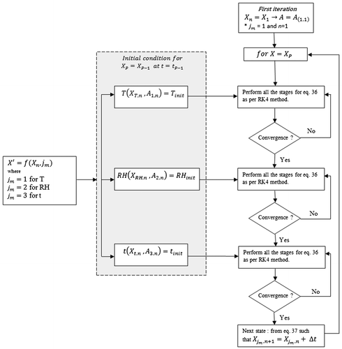
5.2.2. Iterative algorithm to simulate the mass transport of metal ions through defected coating (Implementation)
Evolvement of various metal ions within the delaminated porous metal-coating region, which results due to the parameters (T, RH and t) has been discussed and derived as PDE (Equation (23)) in Section 5.2.1. This Section (5.2.2) implements the methodology for PDE solution using novel iterative algorithm. The physical (or diffusion) parameters (T, RH and t) of PDE (Equation (23)) are needed to be solved simultaneously for specific value of ionic specie concentration
in order to simulate the effect of various metal ion diffusion along the interface. This spatial distribution is integrated in time using finite difference fourth-order implicit RK-4 method as discussed in the previous Section (5.2.1).
Figure depicts the profile of metal ion concentration along one dimension i.e. ‘x-axis’ along metal-coating interface. In this research, the newly developed algorithm encapsulates and makes use of RK-4. The algorithm determines the parameters for the given time t for every stage with ‘h/2’ as the incremental time gap for each parameter which follows the following steps.
The function in Equation (32),
is a (2 × 3) matrix function with
representing two distinct rows each for one function (
) (Equation (33)) and
representing temperature (T), relative humidity (RH) and time of exposure (t) with m = 1, 2, 3, each number representing T, RH and t, respectively.
(38)
From Figure (within highlighted grey box),
,
and
represent three different profiles for temperature (T), relative humidity (RH) and time of exposure (t), respectively, with the initial condition
, where
represents the maximum number of time states (total iterations) programmed before simulation run. Simulation ends when number of (time state) iterations n become equal to total programmed iteration at the start p i.e. n = P.
Within Equation (38), each element of a matrix will be treated with RK-4 method separately. For example, considering element:
, in a temperature profile under initial conditions i.e.
, the next step is applying RK-4 algorithm and incrementing time state as n = n + 1. Where
represents a four-stage incremental process within RK-4 method. Similarly, two other functions for RH and t within the grey box in Figure represents initial condition and are treated with RK-4 method using their respective four-stage incremental processes
and
, respectively. Each element (T, RH and t) is time treated until condition n = p is met and results are stored in separate rows as given in Equation (39)
(39)
where
is a (3 × P) matrix function; P in Equation (39) represents the maximum number of time states/iterations (representing maximum number of columns in Equation (39)) programmed before simulation run.
represents the function (
for calculation of initial conditions.
The first iteration for the simulation program starts with the condition
where jm and n in
are both set equal to 1, as the simulation program will initialize by considering the first iteration, n = 1 and temperature (T) profile with representation,
. After performing the four-stage increment and approaching convergence, the process will move to the next profile (i.e. RH) and again perform the four-stage increment until a given convergence criterion is reached.
(40)
where
represents the nth iteration with four-step incremental process for
variable (T, RH and t). The term r representing one of four sub-steps (
,
,
,
) as per Equation (36).
represents the convergence parameter value which is initially set before the simulation run.
6. Reliability modelling for metal-coating interface
Material properties, environmental parameters (weather, concentration of salts in air) and physical parameters (T, RH and t) may vary uncertainly with the time, so stochastic approach is needed to identify corrosion initiation and failure due to the ionic transport during metal-coating delimitation. The lifetime assessment [Citation34] was performed for under-coating corroding metal (substrate) using probabilistic model.
6.1. Corrosion initiation
The ionic compound concentration inside the defect on coating reaches the activation concentration point at time
which is the instance at which the corrosion reaction at the under coating metal surface begins. The time of corrosion initiation depends upon time-dependent ionic compound concentration along a delaminated porous interface (defect). Time-varying PDE (
) for the ionic compound concentration is a probability density function (PDF) [Citation34,35] over the time range of
–
(This has been solved and implemented in Section 5.2 using iterative algorithm incorporated with RK-4 method). where te is the end time at which ionic transport concentration along the interface depletes. The cumulative density function (CDF)
is,
(41)
where . The term
in Equation (33) represents the PDF in Equation (23) for the type of metal ion (S1, S2 … Sn) along the interface. The PDF (Equation (23)) will be a function of ionic (metal ions) transport through delaminated porous region. The function
in Equation (33) can again be written back in terms of ionic transport representation as in Equation (23) which gives the form,
(42)
where is the concentration of ionic specie inside the delaminated porous region (defect) at time t and distance x, while
is the surface coating thickness over the metal surface. The ionic concentration at the point of activation of corrosion
is always greater than
.
6.2. Instantaneous failure probability
The instantaneous failure probability P(t) is the ratio of probability of failure due to the ionic specie transport at the interface (which is represented using function in Equation (41)) inside the delaminated porous region (defect) to the probability of operating without failure N(t)
when
, so
(43)
(44)
where is the CDF (cumulative density function) and is found using Equation (41).
7. Simulation results and discussion
7.1. Simulation study for uncertain vehicle position
The simulation model was developed for estimating the uncertain use of vehicle in controlled and uncontrolled environments. The model considered the use of vehicle in various environments on daily basis represented by N in Table . The initial probability p was set to 0.4 and probability of vehicle use in controlled environment was calculated using function for a day, and then an iteration method was applied as given in Figure . The function PM =
estimates the maximum value among all the probability values calculated for that particular day and the value of c against max probability PM is stored as shown in third column of Table . Table shows the results of use of vehicle for nine days. c calculated for each day can randomly occur among N times daily use.
Table 3. Showing application of vehichle to the controlled environment c estimated using iteration method in Figure . Total number of environmental conditions applied to vehichle on daily basis N.
The table stores the values for N, PM and c for each day up till nine days. The simulation study was performed for nine days (as shown in Table ) in which total of 54 one-side trips were considered in order to estimate the total value of cT after nine days. Random number was generated between 1 and 9, for each day up till nine days. However, N can be set to the actual value of number of times of daily vehicle use for the case when the developed model is subjected to real-world application. Figure shows the plot for the values of Table .
Figure 7. Plot indicating the number of times the vehicle is used in the controlled environment (indicated as 1) and uncontrolled environment (indicated as 0).
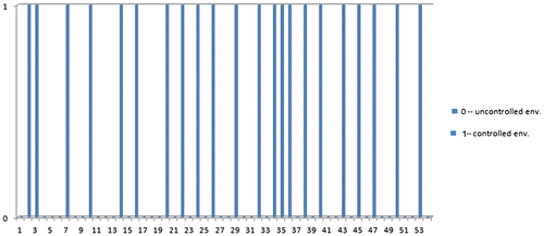
In the plot from Figure , ‘1’ represents c (controlled environment) and 0 represent ‘uc’ (uncontrolled environment) e.g. considering day 1 from Table . N = 6 and c = 2, there will be two pulses and the rest four will be zero pulse (non-pulse).
7.2. Analytical study for influence of vehicle position and weather variability over ionic compound concentration on vehicles body (combined model)
Figure illustrates the analytical study performed for first 20 values (0 and 1) taken from Figure . Each pulse ‘1’ and non-pulse ‘0’ represents application of vehicle to controlled and un-controlled environments, respectively. Each pulse and non-pulse prevails for certain time in hrs. It is assumed that the vehicle is being used during the winter season.
Figure 8. Plot showing pulses ‘1’ and non-pulses ‘0’ for un-controlled and controlled environments, respectively, and illustrating the time-dependent variation of ionic compound concentration over metal-coating.
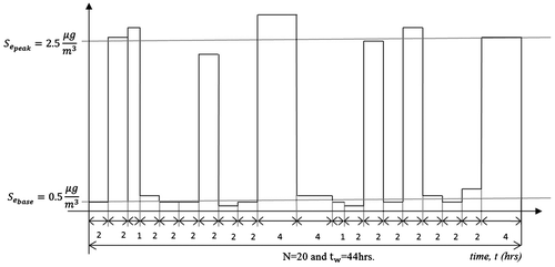
The value of ionic compound concentration varies with the time which means that during each application to a certain environment, the concentration of ionic compound accumulation on coating surface can vary. So average value is calculated as,
(45)
(46)
With reference to Figure and Equations (45) and (46), out of N = 20, vehicle is used seven times (seven peaks) in uncontrolled environment and 13 times (13 bases) in controlled environment so, uc = 7 and c = 13, Thus, the overall concentration of ionic compound accumulated, during winter season is,
(47)
(48)
The concentration of ionic compound depending on the time of use of vehicle in any type of environment (controlled and uncontrolled) is,
(49)
The time for which vehicle is used in uncontrolled and controlled environments is and
, respectively, where
. Thus, total concentration accumulated during use of vehicle in uncontrolled environment is,
(50)
Now, for controlled environment,(51)
Similar study can be performed for the summer season using a set of Equations (45)–(51). The study models the accumulation of ionic compound over metal-coating which is time dependent i.e. the width of each pulse and non-pulse (width of pulse represents the time of use of vehicle during controlled or uncontrolled environment) plays a vital role in deciding the overall accumulation of ionic compound in both the environments.
7.3. Simulation results of iterative algorithm for mass transport of metal ions through defected coating (implementation of PDE)
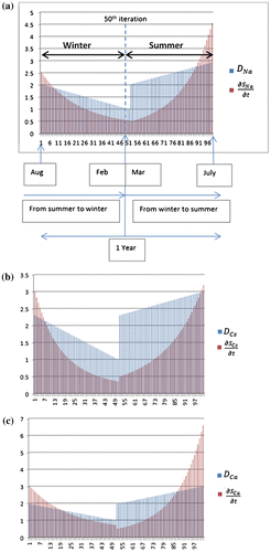
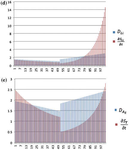
The comprehensive simulation study was performed to implement the PDE (Equation (23)) incorporating RK-4, using novel simulation algorithm in Figure (Section 5.2.2). The simulation model was designed to perform 100 iterations by initially setting p = 100 (P is discussed in point (ii) of Section 5.2.2). The first 50 iterations were designed specifically for the winter season, considering all the parameter values according to winter season, while the rest of the iterations (next 50) were designed considering the parameter values for the summer season. Here, each iteration shows the transfer from one time state (tn) to the next time state (tn + 1). Likewise, the variation in time states accounts for variation in respective parameter (T, RH and t) values of and
. The transfer between various states is accompanied by four sub-stages as per RK-4 algorithm. Each time step for various sub-stages is set to h/2 (but it is possible to vary time step according the requirement for the length of each time state n).
The simulation study was performed for each type of metal ions (cations) like Na+, Ca+2, Cs+ and Li+ separately as shown in Figure (a)–(d). The initial average ionic concentration (high) of each metal ion at the start of winter was set as: Na (2.5 ), Cs (3
), Ca (3) and Li (1.7
), while average concentration (low) at the start of summer was set as: Na (0.5
), Cs (0.5
), Ca (0.5
) and Li (0.5
). These metal ions are produced due to dissociation/separation of ionic compound into smaller particles inside delaminated region and their concentration varies along the interface with the passage of season (winter and summer) due to change in T, RH and t. The diffusion rate for various hydrated cations inside the delaminated region was set in the order as Li+ < Na+ < Ca+2 < Cs+(according to Table ).
Figure 9. (a)–(e) Simulation results for diffusion and concentration gradient values for winter and summer seasons represented as iterations with winter from iterations 0 to 50 and summer from 51 to 100.
Table 4. Diffusion coefficient values of metal ions in water vapours at room temperature (25 °C/298 K) and 30% RH (in units of 10−5 cm2/sec).
With reference to Figure (a), as initially the ionic compound concentration (shown by red lines) is higher at the start of winter season (August) so, metal ions concentration gradient for sodium (Na)
will also be higher but will decrease continuously from August to February as shown by iterations (1–50). Winter is at its peak in the month of February, thus, ionic compound concentration
will be least. Further, for diffusion rate (DNa) (shown by blue lines), at the end of winter seasons (February), the temperature (T) and relative humidity (RH) are low which will result in declining values of diffusion rate (DNa) from summer to winter.
After the 50th iteration, parameters reset according to the start of summer season (March), with initial ionic compound concentration set to lower value for the month of March. The transport rate
during the summer season will keep on increasing from March to July with the iterations (51–100). Summer is at its peak in the month of July, thus, ionic compound concentration
will be the highest. Further, for diffusion (DNa), as temperature (T) and relative humidity (RH) values are highest in July as shown in the figure. Figure (a) shows that the plot for diffusion rate values of Na (sodium) along the interface is the highest in July compared to that in March.
The simulation results for other ionic species (Cs, Ca and Li) are shown in Figure (b)–(d). The same procedure as applied to Figure (a) also applies to other species as well which are shown in Figure (b)–(d). Figure (e) is the cumulative average sum of concentration gradient (transport) and diffusion
of Na, Cs, Ca and Li shown in Figure (b)–(d).
7.4. Simulation results for local current density (corrosion current) vs. ionic compound concentration
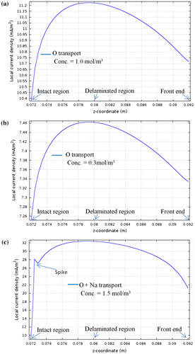
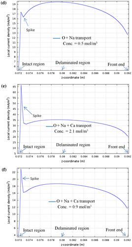
The simulation study (in this section) was performed in order to analyse the effect of ionic compound concentration on local current density, i(t) (mA/m2) (along z-coordinate in Figure) which in turn relates corrosion rate cr(t) in Equation (22). From our recently completed research,[Citation19–23] it was estimated that concentration of metal ions plays a major role in metal degradation. It can be seen from Figure (a) and (b) that as the concentration of O propagation towards exposed metal increases from 0.3 mol/m3 to 1 mol/m3 the local current density also rises from 7.45 to 11.1 mA/m2. Similarly, the overall ionic compound concentration rises due to sodium and calcium ion ingress through defected coating compared to the case when just O has propagated results in the rise of local current density as shown in Figure (c) and (f). In this simulation study, as per Equation (22), the local current density i(t) is dependent on uncertain vehicle movement, varying weather, Temperature and RH. ‘z-co-ordinate’ indicates the distance from intact region (0.072 m) to defected region (0.092 m) over metal-coating interface in all the figures. It can also be seen that the current density is minimum at metal-coating intact region (0.072 m) and continuous to increase along the delaminated region (0.080 m) and almost remains constant (in Figure (c)–(e) till the front region (0.092). However, this constant line behaviour was not observed for O, yet it could be seen for cases with higher concentration of species like in case of Figure (c)–(e).
Figure 10. (a)–(f) Plots showing the dependence of local current density on ionic compound concentration. X-axis indicates the profile of concentration along the metal surface. 0.072 m is the intact region and from there, onwards, the front and delaminated regions.
The spikes seen in Figure (c)–(f) is due to the Galvani potential at the point of intact between metal-coating. At the metal-coating intact point, electron flow between the two will take place because of the voltage difference and continue until the Fermi level of the electrons come in equilibrium. This results in the formation of electrical double layer at the interface. The line graph in Figure relates to Equations (20)–(22), where it is evident that the metal loss is directly proportional to the concentration gradient of metal ions. However, the concentration gradient through defected coating varies with weather, frequency of use of vehicle in controlled and uncontrolled environments.
8. Conclusions
The paper presents a cutting edge model for metal-coating delamination incorporating variable environmental parameters (weather and ionic compounds in air) and uncertain movement of vehicle in controlled and uncontrolled environments. Conventional research was focused on metal-coating bond breakage and pH effect due to oxygen reduction on delamination process. The presented model was developed considering all the uncertain parameters (weather, variable concentration of ionic compound, type of object e.g. vehicle, use of vehicle in certain environment and frequency of use of vehicle in various environments). The developed model takes into account the uncertain use of vehicle in variable environment (controlled and uncontrolled). All these parameters play a vital role in metal-coating delamination, as vehicle movement is uncertain.
Stochastic approach was used to model uncertain position and was related with changing weather. Weather decides the concentration of ionic compound deposition over metal-coating (vehicle’s body). However, diffusion of these metal ions through delaminated zone to the front end of metal depends upon temperature (T), relative humidity (RH) and time of exposure (t). During winter, concentration levels of ionic compound were recorded to be high but investigations show that diffusion rate is low and similarly the opposite case was noted for the summer. The model was precisely built taking in to account all such observations. A detailed simulation study was performed and results were deeply analysed.
Acknowledgement
This research is jointly funded by the Defence Science & Technology Laboratory (DSTL), Ministry of Defence (MoD) and Bournemouth University UK. The authors acknowledge their support and contributions.
References
- Burns RM, Bradley WW. Protective coatings for metals. 1967. Available from: http://www.amazon.com/Protective-Coatings-Metals-Bradley-Burns/dp/0278920861
- Huang M-W, Allely C, Ogle K, Orazem ME. A mathematical model for cathodic delamination of coated metal including a kinetic pH–porosity relationship. J. Electrochem. Soc. 2008;155:C279–C92.10.1149/1.2884857
- Ogle K, Morel S, Meddahi N. An electrochemical study of the delamination of polymer coatings on galvanized steel. Corros. Sci. 2005;47:2034–2052.10.1016/j.corsci.2004.08.017
- Ogle K, Tomandl A, Meddahi N, Wolpers M. The alkaline stability of phosphate coatings I: ICP atomic emission spectroelectrochemistry. Corros. Sci. 2004;46:979–995.10.1016/S0010-938X(03)00182-3
- Tomandl A, Wolpers M, Ogle K. The alkaline stability of phosphate coatings II: in situ Raman spectroscopy. Corros. Sci. 2004;46:997–1011.10.1016/S0010-938X(03)00183-5
- Stratmann M, Feser R, Leng A. Corrosion protection by organic films. Electrochim. Acta 1994;39:1207–1214.10.1016/0013-4686(94)E0038-2
- Grundmeier G, Reinartz C, Rohwerder M, Stratmann M. Corrosion properties of chemically modified metal surfaces. Electrochim. Acta 1998;43:165–174.10.1016/S0013-4686(97)00221-1
- Leng A, Streckel H, Hofmann K, Stratmann M. The delamination of polymeric coatings from steel Part 3: effect of the oxygen partial pressure on the delamination reaction and current distribution at the metal/polymer interface. Corros. Sci. 1998;41:599–620.10.1016/S0010-938X(98)00168-1
- Leng A, Streckel H, Stratmann M. The delamination of polymeric coatings from steel. Part 2: first stage of delamination, effect of type and concentration of cations on delamination, chemical analysis of the interface. Corros. Sci. 1998;41:579–597.10.1016/S0010-938X(98)00167-X
- Fürbeth W, Stratmann M. The delamination of polymeric coatings from electrogalvanised steel – a mechanistic approach. Corros. Sci. 2001;43:207–227.10.1016/S0010-938X(00)00047-0
- Fürbeth W, Stratmann M. The delamination of polymeric coatings from electrogalvanized steel – a mechanistic approach. Corros. Sci. 2001;43:229–241.10.1016/S0010-938X(00)00048-2
- Grundmeier G, Schmidt W, Stratmann M. Corrosion protection by organic coatings: electrochemical mechanism and novel methods of investigation. Electrochim. Acta 2000;45:2515–2533.10.1016/S0013-4686(00)00348-0
- Allahar KN, Orazem ME, Ogle K. Mathematical model for cathodic delamination using a porosity–pH relationship. Corros. Sci. 2007;49:3638–3658.10.1016/j.corsci.2007.03.024
- Prawoto Y. Unified model for blister growth in coating degradation using weight function and diffusion concepts. Mater. Corros. 2013;64:794–800.
- Prawoto Y, Dillon B. Failure analysis and life assessment of coating: the use of mixed mode stress intensity factors in coating and other surface engineering life assessment. J. Fail. Anal. Prev. 2012;12:190–197.10.1007/s11668-011-9525-1
- Prawoto Y, Kamsah N, Mat Yajid M, Ahmad Z. Energy density mechanics applied to coating blistering problems. Theor. Appl. Fract. Mech. 2011;56:89–94.10.1016/j.tafmec.2011.10.004
- Prawoto Y. Solid mechanics for materials engineers – principles and applications of mesomechanics. Available from: http://www.amazon.com/MECHANICS-MATERIALS-Principle
- Prawoto Y, Mat Yajid A, Ahmad Z. Coating life assessment: the use of adhesion strength in parametric development in coating degradation evaluation. Adv. Mater. Res. 2012;488–489:427–431.10.4028/www.scientific.net/AMR.488-489
- Saeed A, Khan Z, Clark M, Nel M, Smith R. Non-destructive material characterisation and material loss evaluation in large historic military vehicles. Insight–Non-Destr. Test. Condition Monit. 2011;53:382–386.10.1784/insi.2011.53.7.382
- Saeed A, Khan ZA. Corrosion mapping of historic military vehicles using the TD Focus-Scan. ndtnews. 2010. Available from: http://www.ndtnews.org/content.asp?PageID=1134
- Saeed A, Khan ZA, Hadfield M, Smith R. The effects of fretting corrosion on the durability of drivetrain in large in-use historic vehicles. In: STLE 66th Annual Meeting & Exhibition; 2011 May 15–19; Atlanta (GA): STLE; 2011; p. 73.
- Saeed A, Khan ZA, Hadfield M. Corrosion resistance evaluation of coatings within large vehicles through prohesion testing. In: ASME/STLE 2012 International Joint Tribology Conference – IJTC2012; 2012 October 7–10; Denver (CO).
- Khan ZA, Saeed A, Garland NP. An experimental study of Tribo-corrosion in historic military vehicles. In: 4th UK-China Tribology Symposium Lubricated and Chemical aspects of Wear; 2012 March 29–30; Southampton (UK): Southampton University; 2011.
- Nazir MH, Khan ZA. Surface corrosion analysis and modelling of the Wolverine – M10 military tank destroyer. Forthcoming 2014.
- Weather Underground. 2011. Available from: http://wwwwundergroundcom/weatherstation/WXDailyHistoryasp?ID=IDORSETB5
- Bastidas-Arteaga E, Chateauneuf A, Sánchez-Silva M, Bressolette P, Schoefs F. A comprehensive probabilistic model of chloride ingress in unsaturated concrete. Eng. Struct. 2011;33:720–730.10.1016/j.engstruct.2010.11.008
- Willison M, Clarke A, Zeki E. Seasonal variation in atmospheric aerosol concentration and composition at urban and rural sites in northern England. Atmos. Environ. 1967;1985:1081–1089.
- Martin-Perez B, Lounis Z, Naus D. Numerical modelling of service life of reinforced concrete structures. In: Proceedings of 2nd International RILEM Workshop on Life Prediction and Aging Management of Concrete Structures; 2003 May 5–6; Paris: RILEM; 2003 p. 71–79.
- Samson E, Marchand J, Snyder K. Calculation of ionic diffusion coefficients on the basis of migration test results. Mater. Struct. 2003;36:156–165.10.1007/BF02479554
- Baştuğ T, Kuyucak S. Temperature dependence of the transport coefficients of ions from molecular dynamics simulations. Chem. Phys. Lett. 2005;408:84–88.
- Laidler KJ. The development of the Arrhenius equation. J. Chem. Educ. 1984;61:494–498.10.1021/ed061p494
- Sørensen PA, Kiil S, Dam-Johansen K, Weinell C. Influence of substrate topography on cathodic delamination of anticorrosive coatings. Prog. Org. Coat. 2009;64:142–149.10.1016/j.porgcoat.2008.08.027
- Butcher JC. Implicit Runge-Kutta processes. Math. Comput. 1964;18:50–64.
- Hartzell AL, da Silva MG, Shea HR. Lifetime prediction. MEMS Reliability. Stanford (CA): Springer; 2011. p. 9–42.
- Parzen E. On estimation of a probability density function and mode. Ann. Math. Stat. 1962;33:1065–1076.10.1214/aoms/1177704472

