Abstract
Wind turbine blades are made of integrated composite parts bonded together using structural adhesives. The blades are among the most severely multi-axial fatigue loaded structures and the bonded joints play an important role in their structural integrity. For better understanding of the mechanical performance of the bonded joints, thorough knowledge is required on the multi-axial behaviour of the bulk adhesive. In this study, tubular specimens consisting of glass/epoxy bonding paste were subjected to uniaxial (tension, compression and torsion) and biaxial (tension–torsion and compression–torsion) static tests. Different biaxial ratios were used and the stress–strain responses were recorded using strain-gauges. The imposed biaxial stress ratios influenced the stress–strain behaviour of the material system, especially the compression and the shear stress–strain. A material model was developed based on the experimental observations taking into account the non-linear behaviour and the effects of the biaxial ratios and it was implemented together with a progressive damage scenario into a finite-element model. The experimental failure patterns were compared with the numerical simulations and a good match was found.
1. Introduction
The size of the wind turbines has increased over the last years and to achieve the wind energy targets, designs of even larger Wind turbine blades (WTBs) are in progress. To meet this challenge, a thorough knowledge of materials’ behaviour and understanding of their structural response is required in order to develop reliable tools for designing such large structures.[Citation1]
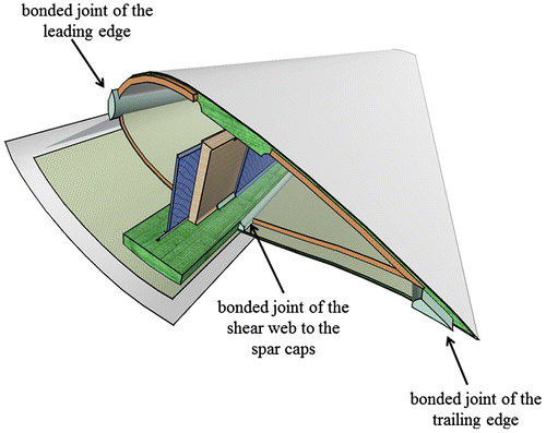
The blades are made of integrated composite parts bonded together using structural adhesives. The adhesives are used to bond the trailing and the leading edge and the shear web(s) to the spar caps. Figure illustrates a cross section of a blade highlighting the bonded joints. The blades are among the most severely multi-axial fatigue loaded structures and the bonded joints play a key-role in their structural integrity. Important characteristics of the bond-lines found in this application are large adhesive thicknesses and volumes, and multi-axial (fatigue) load conditions. For example, the thickness of the bond lines in 70 m blade can reach 30 mm. The geometrical configuration of the bond-lines varies along the WTB and it depends mainly on the design of the blade and the manufacturing tolerances.
Numerous studies have been carried out on the multi-axial performance of various types of bond-lines in various applications, e.g. [aerospace and automotive industry]. However, a limited number of studies can be found in the literature about the mechanical performance of adhesive bonded joints with thick bond-lines, about materials and load conditions (fatigue) typical for the wind turbine rotor blade industry. The studies can be divided into two categories; studies on coupon level and studies on component level.
1.1. Coupon level
Zarouchas and van Hemelrijck performed tensile and compressive static tests on thick adhesive dog bone specimens, commonly used in WTBs, using acoustic emission and digital image correlation techniques in order to assess the damage process during the loading procedure.[Citation2] It was found that the adhesive had three damage mechanisms. A relationship between these mechanisms and the acoustic activity was established. The first mechanism was development of micro-cracks in the adhesive. The second mechanism, which was dominant in terms of acoustic energy released, was development of multiple matrix macro-cracks. Finally, the third mechanism involved fibre breakage and fibre pull-out.
Samborsky et al. performed an experimental campaign of static and fatigue tests on typical scaled blade joints.[Citation3] Variations on the geometrical configuration of the joint, the influence of manufacturing defects and the effect of reinforcements were investigated. Two different geometries were studied; a 45°-wedge block and a 90°-wedge block. The static strength of the two different geometries was similar, however, the second geometry displayed larger scatter. The fatigue life was relatively low for both geometries in comparison to the reinforced specimens. Finally, the manufacturing defects influenced mostly the failure pattern and not the fatigue life. In most cases, crack initiation and initial growth were cohesive in the adhesive, shifting to interlaminar in the adherend as the cracks extended.
Sears et al. used three different test methods – notched lap shear, crack lap shear and mode I DCB tests – to performed fatigue tests on thick adhesives.[Citation4] The notched lap shear test results for static loading explored a variety of parameters. Significant effects of overlap length, adhesive thickness and applied load direction were observed. Fatigue data were obtained for three loading conditions (tension, reversed loading and compression) with two blade adhesives, one relatively brittle (ADH-1) and the other relatively tough (ADH-6). Fatigue results were similar for the two adhesives despite their toughness difference, which was evident in the crack propagation phase of the lifetime. The fracture mechanics-based test methods with artificial starter cracks used the strain energy release rate as a metric for static fracture and fatigue crack growth. The mixed mode cracked lap shear test was run under reversed loading to obtain fatigue crack growth data; the data were separated by the GI/GII ratio, which varied with crack length for this geometry. Crack growth rates were higher for higher GI/GII ratios.
Hua et al. investigated numerically the performance of adhesive joints of carbon/epoxy WTBs.[Citation5] It was reported that taking into account the plasticity of the adhesive material, the out-of-plane components of normal (peel stresses) and shear (interlaminar) stresses were reduced 8.2 and 13.3%, respectively. By adding a fillet at the edge of the joints, the peel stresses were reduced. Inclusion of voids in the adhesive led to strength reduction of the joint with prior crack initiation.
Recently, Masmanidis and Philippidis developed a continuum damage model, implemented in a finite-element coding, for simulating damage propagation in joints with secondary bonding and co-bonding.[Citation6] They introduced a bilinear softening model for the adhesive and it was combined with a failure criterion suitable for brittle polymers. They also implemented a progressive damage model for the composite adherents. In the case of the co-bonding joint, the authors replaced the composite plies at the joined faces by a two-layer effective material consisting of modified composite and a distinct polymer layer. That approach was based on an earlier concept developed by Puppo and Evensen [Citation7]. The authors observed that the numerical simulations provided satisfactory results for predicting the ultimate loads and the joint strength did not increase for overlap lengths greater than 150 mm.
1.2. Subcomponent level
In the second category, subcomponent level, composite I-beams, representing the shear web – to – spar caps connections were tested in static and fatigue investigating the mechanical performance of the bond line under realistic stress fields.
A comprehensive study on the mechanical behaviour of such a composite I-beam structure was performed in the framework of the work package 3, ‘Rotor Structures and Materials’ of the UpWind project.[Citation8] Two different geometrical configurations were examined; the first one had a symmetric cross section, while the second had an asymmetric cross section. The I-beams were subjected to static and fatigue loading in different test configurations, monitored by several non destructive testing techniques and were analysed numerically using finite-element modelling. A summary of this experimental and numerical campaign can be found in the following report [Citation9]. The partners provided a list of recommendations regarding the design, modelling and testing of, similar to the UpWind I-beams, composite structures.[Citation10]
Zarouchas et al. [Citation11] performed 4-point bending tests to investigate the mechanical behaviour of the 10-mm thick bond line of the ‘UpWind’ I-beams. In parallel, the authors developed an algorithm implemented in Finite-Element Modelling (FEM) to simulate the damage evolution. Besides that, the algorithm provided useful data about local effects induced by the experimental set-up. As a result, a list of recommendations was provided on how to perform the tests. Zarouchas performed structural assessment of the I-beams during cantilever tests using Acoustic Emission and Digital Image Correlation Techniques.[Citation12] The author developed an algorithm to identify the structural failure mode by coupling wavelet analysis with pattern recognition algorithms. It was observed that the geometrical configuration of the joint affects the structural performance resulting in dissimilar failure patterns because the multi-axial stress fields developed in the bond line differed in each geometrical configuration.
Partners of the UpWind project manufactured and tested subcomponents similar to the UpWind I-beam structure. I-beams were built from two composite C-beams bonded to flanges and were tested in three- and four-point bending tests in Knowledge Centre Wind turbine Materials and Constructions. Details can be found in [Citation13]. In Fraunhofer IWES, an I-beam structure was designed, manufactured and tested under static and fatigue loading in an asymmetric three-point bending configuration.[Citation14] The I-beam was used to investigate the influence of different design variables and manufacturing techniques. It was reported that the axial stress component in length direction of the blade, longitudinal, was the dominant. However, the authors described the existence of additional stress components; axial stress in the transverse direction about to 10–25% of the longitudinal axial stress and shear stress components up to 10% of the longitudinal axial stress. They highlighted the importance of taking into account the multi-axial stress field in the structural design process of the joints. Moreover, they observed that single voids causing surface stress concentrations did not affect the structural fatigue life. Contrarily, reinforcements such as the cover laminate on the bond line had a significant influence on the joint life, resulting in an increase of a factor of 50 at low cycles and of 30 at high cycles. Similarly, Sharp et al. developed an integrated 3D woven Pi-joint representing the connection of the shear web to spar caps as a novel design of the adhesively bonded joint.[Citation15] They manufactured and tested I-beams and they observed that the Pi-joint eliminates catastrophic failure in the bond-line. The strength of the I-beams was higher and the dominant failure mechanisms changed in comparison to I-beams made with the current bonding technology. Contrary to [Citation14], they observed that voids in the adhesive would lead to reduced joint strength with earlier crack initiation.
The literature review reveals that the thick bond lines are subjected to multi-axial stress field and, contrary to the adhesively bonded joints with thin bond-lines which mainly serve to transfer shear stress, it is crucial to taking this stress field into account in the design process. Thus, for better understanding of the damage process and the failure patterns observed in the bonded joints of the WTBs, more knowledge is required on the multi-axial behaviour of the bulk adhesive. This paper presents a study of the mechanical behaviour of the adhesive. It provides experimental results for the characterization of its elastic properties for the development of a material model and simulation of the tests using a progressive damage methodology in FEM. Section 2 presents the material system and the manufacturing process. In Section 3, the experimental results of uniaxial and biaxial tests are presented giving emphasis on the influence of the biaxial ratio to the stress–strain responses. Section 4 discusses the material model and the development of the progressive damage scenario implemented in the commercial finite-element software package Marc MSC.[Citation16] It should be mentioned that previous results of the experimental campaign were documented in [Citation17].
2. Material system and manufacturing process
The adhesive EPIKOTETM MGS Paste 135/G-series was used. The adhesive is a solvent-free epoxy-based bonding paste (adhesive with short glass fibre filler) with a wide range of applications. It can be processed using different hardeners, depending on the application. The EPIKURETM Curing Agent MGS BPH 135G, as a medium-speed hardener, was used in the present study. The mixing ratio (by weight) was 100:45.
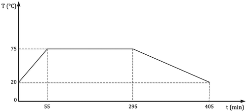
The mixing process was performed manually, at room temperature, 20 °C. Figure illustrates the time schedule for the curing process which is recommended by the supplier. The specimens were checked through visual inspection using a flashlight and specimens with voids were excluded from the experimental campaign.
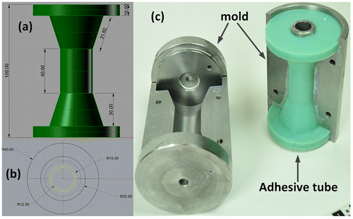
A novel tubular configuration was designed, mainly driven by the ease of manufacturing and biaxial testing procedure. Figure presents the tubular specimen where the thickness of the gauge section is yellow highlighted and it is 2.5 mm. An in-house manufactured mould was used to produce the tubes. A hollow cylinder steel bar was placed in the centre of the mould and once the tube was fully cured, it was manually removed. The outer surface of the steel bar was cleaned by release agent enabling to remove it without damaging the tube.
3. Uniaxial and biaxial tests
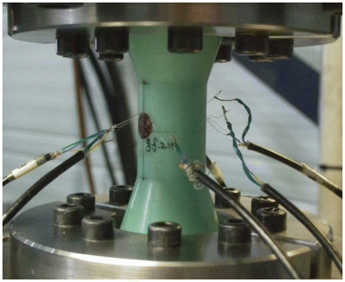
All the tests were performed using a SCHENCK 250 kN / 4 kNm test frame. Figure illustrates the experimental set-up. The uniaxial tests were performed under displacement control using a rate of 1 mm/min, while the biaxial tests were performed under load control so as to enable constant biaxial stress ratio. Within this study, the biaxial stress ratio is defined as the ratio of the normal stresses to the shear stresses in the gauge section:(1)
where σ indicates normal stress, imposed by the axial load, τ indicates shear stress in the outer surface of the gauge section, imposed by the torsion load, and the subscripts indicate tension or compression (positive values for tension, negative for compression). For example, for a tension–torsion test where the normal stress is five times higher than the shear stress, the ratio is defined as 5/1. The strains were recorded by strain-gauges. Two 3-element rosette strain-gauges were bonded opposite each other in the gauge section, with the sensor elements oriented at 0°, 90° and 45° with respect to the longitudinal axis of the specimen, see Figure .
Tables present a summary of the elastic properties and ultimate strength and strain for the uniaxial tests. Thirty tubes were subjected to uniaxial and biaxial tests; 6 tubes under uniaxial tension, 6 under uniaxial compression, 6 tubes under torsion and 12 tubes under biaxial load with several loading ratios. The initial elastic moduli were calculated in the range between 0.05 and 0.25% strain for the tension, –0.05 and –0.25% strain for the compression and 0.1 and 0.3% strain for the torsion tests. Furthermore, Table presents the failure loads and stresses per biaxial stress ratio. A unique identification number was assigned to each tubular specimen and it is mentioned as specimen identification.
Table 1. The tensile elastic properties of the adhesive tube.[Citation18]
Table 2. The compressive elastic properties of the adhesive tube.[Citation18]
Table 3. The shear elastic properties of the adhesive tube.[Citation18]
Table 4. The biaxial failure loads and stress.
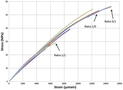
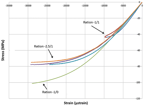
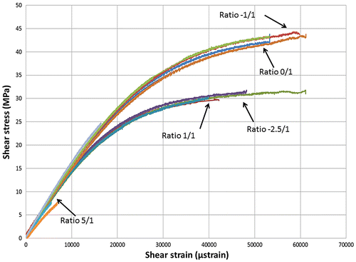
Figures depict the axial and biaxial tensile, compressive and shear stress–strain curves and each stress ratio is highlighted. The influence of the biaxial ratio to the stress–strain curve is higher for the compression and shear response in comparison to the tensile response. More specifically, the strains for the –2.5/1 ratio are in the same range with the uniaxial compression test, while the failure compression stress of the –2.5/1 is almost 20% lower than the –1/0. For the case of the –1/1 ratio, the compression acts positively on the shear strength which is increased 14% in comparison with the uniaxial shear strength. Finally, the couple 1/1, –2.5/1 presents similar behaviour.
4. Numerical analysis
4.1. Material model and constitutive law
As presented in Section 3, the material behaviour of the adhesive is non-linear and the shape of the experimental curve changes with the biaxial stress ratio. To take into account, the non-linearity and the influence of the biaxial stress ratio, incremental stress–strain steps were implemented using the non-linear constitutive law introduced by Richard and Blacklock [Citation19].(2)
(3)
(4)
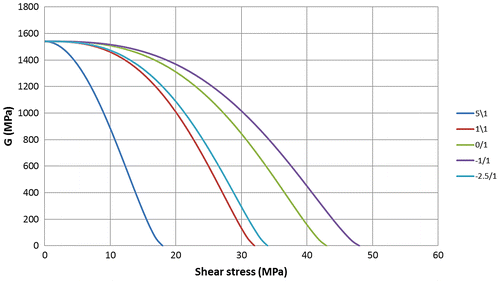
Et0, Ec0, G0, σt0, σc0, τ0, nt, nc and ns are model parameters which are defined by fitting the experimental curves. More specifically, Et0, Ec0, G0 are the initial elastic moduli, the σt0, σc0, τ0, are the asymptotic approximations and the nt, nc, ns are constant numbers of the power functions in Equations (2)–(4). The values were found different for different biaxial stress ratios. Table presents the parameters’ values.
Table 5. The model parameters for different biaxial stress ratios.
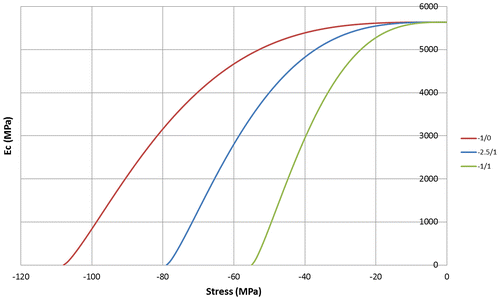
Figures and present the degradation of the compression and shear modulus in function of the stress level for the different biaxial ratios, respectively. The curves were designed by Table using Equations (3 and 4).
4.2. Finite-element modelling
FEM was used to simulate and compare with the experimental observations of the uniaxial and biaxial tests. A 3-D model was developed using 8-node linear solid elements with three degrees of freedom per node: translation in the nodal x, y and z direction. The element has plasticity, stress stiffening, large deflection and large strain capabilities. A damage scenario was implemented, based on the progressive damage modelling technique developed by [Citation12]. The iterative scenario had four basic steps within a single iteration loop:
| (1) | stress analysis of the coupon | ||||
| (2) | failure analysis in an element basis | ||||
| (3) | degradation of the material properties of the failed elements | ||||
| (4) | application of a global failure criterion. | ||||
The latter step controls when the simulation stops because the final failure is satisfied which physically means that the coupon cannot withstand any additional loading. The solver of MARC MENTAT was used to perform the stress analysis.
Table 6. Degraded elastic properties of the adhesive.
Table 7. Failure experimental and numerical stresses.
The failure criterion, proposed by Stassi D’Allia was employed and the bulk adhesive was assumed to behave as a brittle isotropic material because there was no yield point and failure process was sudden. In general, the parabolic failure criterion states that failure occurs when the distortional strain energy density reaches a limiting value, which in this case was equal to 1.[Citation20](5)
where
σfτ, σfc and τf represent the adhesive tensile, compressive and shear strength.
Material properties degradation was performed on an element basis meaning that if the failure criterion was satisfied, the elastic properties of the failed element were degraded. The degradation rules are usually based on phenomenological observations that include several assumptions. Within this study, the degradation rules, that were used for the simulation of the failure in the bond line of composite I-beams, were implemented [Citation12]; the elastic and the shear moduli were adjusted to 0.001 GPa (a value very close to zero) in order to avoid numerical instabilities.Table summarises the material properties degradation.
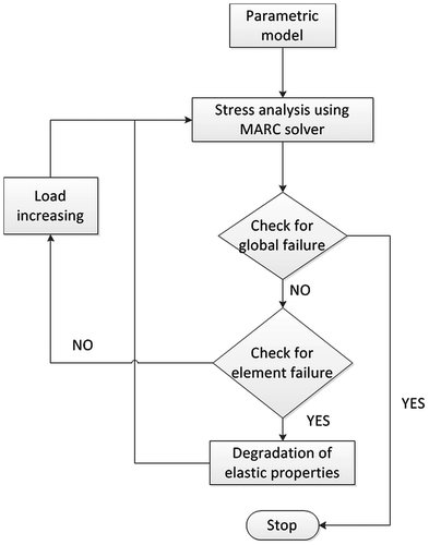
A programe, using the programming language PYTHON,[Citation21] was developed to implement the damage scenario and simulate the tests. The programme is depicted in the following flowchart, Figure . The programme involves the following steps:
| (1) | Development of the 3-D model, by giving the initial elastic properties and implementing the constitutive law as it was described in Section 4.1, the boundary and the loading conditions. Parametric modelling was included, facilitating modifications in the geometry. | ||||
| (2) | Stress analysis using the MARC solver to calculate the stress components in each element. Depending on the stress values in each element, the corresponding model parameters of Table were employed. | ||||
| (3) | Check for global failure. The load reaction is calculated for each iteration loop and if it is smaller in N step than in N-1 step, the simulation stops indicating that the tube failed. It should not be the case that the global criterion is satisfied during the first loop. | ||||
| (4) | Check for element failure. If failure occurs, the degradation rules are implemented and the loop returns to the stress analysis without increasing the loading. If failure does not occur, the loop returns to the stress analysis increasing the loading with a pre-defined load step value. | ||||
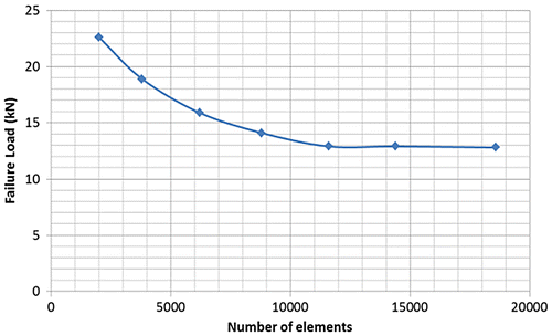
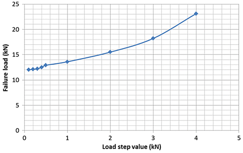
An important input for the simulation is the mesh density and the number of necessary load steps until tube’s failure occurs. A convergence study of the mesh density and the load step value was performed. Both studies were based on the output value of the failure load of the tube. Figure (a) shows the influence of the number of elements on the failure load value for the uniaxial tension tests and by keeping constant the load step value at 0.5 kN. When the element number exceeds 14,400, the model converges to a failure load of 12.9 kN. The converged solution, concerning the mesh density, was afterwards employed to investigate the influence of the load step value. Figure (b) presents how the failure load is reduced while the load step value was decreasing. A further decrease in the load step is not recommended because the relative difference of the failure load for 0.3 and 0.2 kN is only 0.8%. The converged model concerning both the mesh density (14,400 elements) and the load step value (0.3 kN) was further employed for solving the different biaxial loading cases.
Figure 11. Convergence to a certain failure load while (a) increasing the number of elements and (b) decreasing the load step value.
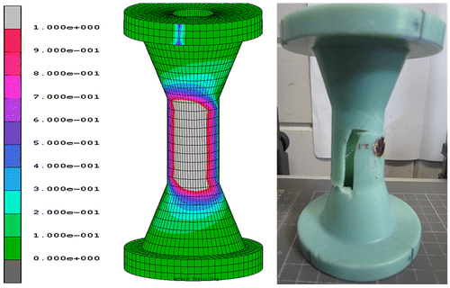
Table summarises the experimental and numerical failure stresses for all the axial to shear stresses ratios. Figures and compare the total failure locations as captured from the experiments and the one predicted from the simulations for two different stress ratios (1/0 and 1/1). The failed elements based on the developed progressive damage scenario are presented in light grey scale. The contour represents the damage scale D, Equation 5. The simulated failure patterns match well with the experimental results.
Figure 12. Comparison between the experimental observations and numerical results for the 1/0 loading ratio (uniaxial tension).
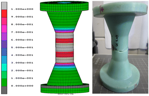
Figure 13. Comparison between the experimental observations and numerical results for the 5/1 loading ratio (biaxial tension–torsion).
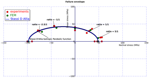
Finally, Figure presents a comparison between the experimental (red circles) and numerical (green stars) failure stresses and the analytical biaxial failure envelope developed using the failure criterion of Stassi D’Allia (blue line).
5. Conclusions
This study focused on the mechanical characterization, experimentally and numerically, of a structural adhesive commonly used in WTBs. An experimental campaign was performed to measure the elastic properties of the material under uniaxial and biaxial loading. Accordingly, numerical simulations of the uniaxial and biaxial tests were performed, implementing the experimental observations in a finite-element model and using a progressive damage scenario. The main conclusions are:
| (1) | The structural adhesive exhibited non-linear behaviour under tension, compression and torsion loading. A power function was used to fit the experimental results and the model parameters were found to be different for each loading condition. | ||||
| (2) | The tension stress–strain responses under different biaxial ratio loadings were not altered. Contrarily, the compression and the shear stress–strain responses did change resulting in different compression and shear moduli for each biaxial loading case. This is crucial for the optimal structural design of the bond lines in blades, meaning that the alteration of the moduli should be taken into account. | ||||
| (3) | The experimental observations were successfully implemented in a finite-element model. The material model that described the adhesive could accommodate different constitutive equations and the respective elastic properties were employed based on the stress state of each element. | ||||
References
- Mishnaevsky L, Jr., Brøndsted P, Nijssen RPL, et al. Materials of large wind turbine blades: recent results in testing and modelling. Wind Energy. 2012;15:83–97.10.1002/we.v15.1
- Zarouchas DS, van Hemelrijck D. Mechanical characterization and damage assessment of thick adhesives for wind turbine blades using acoustic emission and digital image correlation techniques. J. Adhes. Sci. Technol. 2014;28:1500–1516.10.1080/01694243.2012.698122
- Samborsky DD, Sears AT, Mandell JF. Static and fatigue testing of thick adhesive joints for wind turbine blades. Paper presented at ASME Wind Energy Symposium. 2009 Aug 30; San Diego, CA, USA.
- Sears AT, Samborsky DD, Agastra P, et al. Fatigue results and analysis for thick adhesive notched lap shear test. Paper presented at AIAA SDM, Wind Energy Session. 2010 Apr 12–15; Orlando, FL, USA.
- Hua Y, Kasavajhala ARM, Gu L. Elastic–plastic analysis and strength evaluation of adhesive joints in wind turbine blades. Compos. Part B. 2014;44:650–656.
- Masmanidis IT, Philippidis TP. Progressive damage modelling of adhesively bonded lap joints. Int. J. Adhes. Adhes. 2015;59:53–61.10.1016/j.ijadhadh.2015.02.001.
- Puppo AH, Evensen HA. Interlaminar shear in laminated composites under generalized plane stress. J. Compos. Mater. 1970;4:204–220.10.1177/002199837000400206
- http://www.ewea.org/fileadmin/ewea_documents/documents/upwind/21895_UpWind_Report_low_web.pdf02.05.2015
- Stammes E, Sayer F. Comparison and evaluation of beams tested within WP3, UpWind document, WMC-2011-14, March 2011.
- Stammes E, Westphal T, Nijssen RPL. Guidelines for design stress analysis and testing of a structural blade detail, UpWind document D3.1.4, March 2011.
- Zarouchas DS, Makris AA, Sayer F, et al. Investigations on the mechanical behavior of a wind rotor blade subcomponent. Compos. Part B: Eng. 2012;43:647–654.10.1016/j.compositesb.2011.10.009
- Zarouchas DS. Experimental and numerical investigation of wind turbine blade subcomponents [PhD dissertation]. Brussels: Free University of Brussels; 2012.
- Nijssen RPL, Westphal T, Stammes E, et al. Rotor structures and materials strength and fatigue experiments and phenomenological modelling. Paper presented at European Wind Energy Conference. 2008 30 Mar–3 April. Brussels: Belgium.
- Sayer F, Antoniou A, van Wingerde A. Investigation of structural bondlines in wind turbine blades by sub-component tests. Int. J. Adhes. Adhes. 2012;37:129–135.10.1016/j.ijadhadh.2012.01.021
- Sharp K, Bogdanovich A, Boyle R, et al. Wind blade joints based on non-crimp 3D orthogonal woven Pi shape performs. Composites Part A. 2013;49:9–17.10.1016/j.compositesa.2013.01.012
- Marc and Mentat Release guide 2010. MSC. Software GmbH: Munich (Germany).
- Canales AG, Stammes E, Nijssen RPL. Shear properties of bonding paste comparison of different test methods and the effect if bondline thickness on shear strength, technical report WMC-2009-48, 2010.
- Zarouchas DS, Nijssen RPL, van Delft DRV. Failure analysis of structural adhesives in wind turbine blades under multiaxial loading. Paper presented at DURACOSYS Conference. 2012 Sep 17–19; Brussels, Belgium.
- Richard RM, Blacklock JR. Finite element analysis of inelastic structures. AIAA. 1969;7:432–438.
- Allia SFD. Teoria Della Plasticita e Sue Applicazioni [Theory of plasticity and its application]. Denaro G, editor. Italy: Palermo. 1958. http://www.worldcat.org/title/teoria-della-plasticita-e-sue-applicazioni/oclc/9924563
- http://www.python.org/,02-05-2015.

