
Abstract
Bi-adhesive (or mixed-adhesive) joint is an alternative stress-reduction technique for adhesively bonded lap joints. In this work, an experimental study was performed to assess the effect of bi-adhesive bondline on the failure load of mono-adhesive and bi-adhesive single-lap joints. The first step in the experimental study related to mono-adhesive joint, the overlap length was checked using the Global yielding criteria. For the selected overlap length, failure loads of AV138, Araldite 2015 and DP-8005 mono-adhesive joints were determined. It was seen that the highest failure load occurred in the Araldite 2015 mono-adhesive joint. Secondly, the bi-adhesive joints were considered as two different adhesive combinations (AV138 + 2015, AV138 + DP-8005). An interesting result was obtained that the considered bi-adhesive joints with two different adhesive combinations (AV138 + 2015, AV138 + DP-8005) give joint strengths higher than the joint strengths of the adhesives used individually, even if ductile adhesive has a joint strength higher than that of the stiff adhesive. In the last step of this study, experimental investigation was then focused on the determination of optimum bond-length ratio for the bi-adhesive joint. Optimum bond-length ratio for bi-adhesive joint was then investigated using three ratios (0.3, 0.5, 0.7). It is concluded that the adhesive type and the bond-length ratio play an important role in the bi-adhesive bondline. Comparisons of the experimentally determined failure loads and shear strengths with available closed-form solutions were also carried out. Experimental failure loads were in good agreement with those obtained from the Volkersen method and Global yielding criteria.
1. Introduction
Lap joints bonded with structural adhesives have been used extensively in the space, aviation, automotive, and naval industries due to their high strength-to-weight ratio in comparison with the traditional methods such as, fastening and riveting. However, high stress regions at the overlap ends of bonded lap joints reduce their failure load and safety. Eliminating or reducing stress concentrations and maximizing the failure load are vital to ensure the safety of bonded lap joints. The cause of lowering the failure loads of adhesively bonded single-lap joints is the high peel and shear stress concentrations at the ends of the overlap. Therefore, techniques reducing peel and shear stress concentrations are very important to increase the failure load of lap joints.
Today, different techniques have been developed to reduce stress concentrations and hence increase the failure load of lap joints. These techniques are tapering the adherend, forming an adhesive fillet, changing the lap joint geometry, etc. However, these techniques can have some disadvantages. For example, tapering the adherend damages fiber structure of the fiber-reinforced composites and forming an adhesive fillet is quite difficult when using low viscosity adhesives.[Citation1] An alternative technique is to use bi-adhesive bondline. This is accomplished by a combination of stiff and flexible adhesives along the bondline. The stiff adhesive is located in the middle and flexible adhesive at the ends. High stress concentrations at the ends can be reduced using this technique.
Even though adhesively bonded single-lap joints have been widely investigated, only a limited number of papers have been found for bi-adhesive bondline in the open literature and most of these are related to the numerical analysis. Ozer and Oz [Citation1] developed a three-dimensional model of the bi-adhesive double-lap joint based on solid and contact elements. The effect of bondline configuration on the stress distributions was discussed. da Silva and Lopes [Citation2] described variable flexibility and strength along the overlap length as an ideal adhesive joint. They concluded that if the ductile adhesive has a joint strength lower than that of the brittle adhesive, a mixed adhesive joint with both adhesives gives a joint strength higher than the joint strength of the adhesives used individually. Pires et al. [Citation3] investigated a hybrid adhesive joint with aluminum adherends using both experimental and numerical (finite element) techniques. They proved that joint strength can be optimized by choosing appropriate joint geometry and material. Fitton and Broughton [Citation4] used 2D finite element results to compare hybrid and mono-adhesive bondlines. They showed that significant strength improvement can be obtained if the joint failure stresses are considerably less than the shear strength of the adhesive. Temiz [Citation5] studied the effect of a hybrid-adhesive bondline on the strength of double strap joints subjected to external bending moments. He concluded that stress concentration at the overlap ends decreases by applying the flexible adhesive towards the edges of the overlap in bonded joints. Using the flexible adhesive in bi-adhesive joints, the strains do not increase significantly when compared with increase in predicted failure load. Then, he concluded that the adjacent stiffer adhesive has the constraining effect on the strain in the flexible adhesive.
Pires et al. [Citation6] discussed the failure mechanism of bi-adhesive joints. Their results showed an increase in shear strength of the bi-adhesive joints compared with those in which mono-adhesive joints were used over the full length of the bondline. The increase of the lap-shear strength was predicted through finite element model. da Silva and Adams [Citation7] studied titanium/titanium and titanium/composite double-lap joints formed using a hybrid-adhesive bondline. They showed that the suitable combination of two adhesives gives a better performance over a wide temperature range (−55 to 200 °C) than a high temperature adhesive alone for a joint with dissimilar adherends. Bouiadjra et al. [Citation8] proposed a method of repair that consists in dividing the adhesive layer into two bands with different properties. The first band was used on the crack region to ensure the stress transfer and the second band was used beyond the crack region to avoid the adhesive failure. The energy release rate at the crack tip was computed for this repair configuration using the finite element method. They showed that the energy release rate at the crack tips is highly reduced by the difference in properties between the two adhesive bands. Kong et al. [Citation9] performed three-dimensional finite element analyses of hybrid adhesive joints under cleavage and tensile loading. They showed that maximum stresses along the bondline can be decreased using appropriate bond-length ratios. Moreover, they emphasized that it is necessary to take into account the change in loading modes when optimizing the hybrid-adhesive joint.
Marques and da Silva [Citation10] analyzed aluminum double-lap (or patches) specimens with internal taper and dual adhesives by the finite element method and tested them experimentally. They proved that a taper angle of 45° reduces stresses at the end of the patch and, tapered patches are more adequate for stiff adhesives. They stated that joints with dual adhesives have a strength comparable with that of joints with a stiff adhesive alone and are at the same time more flexible and ductile. das Neves et al. [Citation11] developed an analytical model for hybrid-adhesive single and double-lap joints subjected to low and high temperatures. They compared the solutions of the analytical model with a finite element analysis and observed only small differences close to the overlap ends where the maximum adhesive shear and peel stresses occurred.
In their second study, das Neves et al. [Citation12] performed parametric studies and proposed an analytical model to assess the effect the temperature on the maximum adhesive shear and peel stresses. Other parameters such as the overlaps of the low and high temperature adhesives and the effect of the high temperature adhesive modulus on the maximum adhesive shear and peel stresses were also investigated. Kumar and Pandey [Citation13] performed the two-dimensional and three-dimensional non-linear (geometric and material) finite element analyses of adhesively bonded single-lap joints having modulus-graded bondline. The adhesives were modeled as an elasto-plastic multi-linear material, while the substrates were regarded as both linear elastic and bilinear elasto-plastic material. They observed that the static strength was higher for joints with bi-adhesive bondlines compared to those with mono-adhesive bondlines. Kumar [Citation14] proposed a simple analytical framework to study stress intensity and its distribution in a functionally modulus graded bondline (FMGB) adhesive joint based on a variational method. A parametric evaluation was conducted by varying the material and geometric properties of the joint in order to study their effect on stress distribution in the bondline. He concluded that the peel and shear strengths can be optimized by spatially controlling the modulus of the adhesive. Stapleton et al. [Citation15] studied functionally graded adhesives to reduce the peel stress concentrations located near the adherend discontinuities. Grading was achieved by strategically placing glass beads within the adhesive layer at different densities along the joint. They concluded that grading did not result in an increase in strength when the failure without grading occurred in the adherend.
Bavi et al. [Citation16] optimized the geometry of the overlap in mixed adhesive single- and double-lap joints using a modified version of Bees and Genetic Algorithms. They applied size optimization procedures in the mixed bonded joints theoretically. Akpınar et al. [Citation17] investigated the effect of a hybrid-adhesive bondline on the normal and shear stress distributions of T-joints via a non-linear three-dimensional finite element analysis. They indicated that higher degree of shear stress was transferred into the inner regions of the hybrid adhesive. Carbas et al. [Citation18] developed a simple analytical model to study the performance of the functionally graded joints. Developed differential equation was solved by a power series. They validated their analytical model by finite element analysis. Afkar and Camari [Citation19] studied the effect of ceramic volume fraction of the functionally graded materials (FGMs) on the stress concentration. They showed that using bi-adhesive joint together with high-ceramic volume fraction FGMs can significantly reduce the shear and peel stress in the lap joint. Oz and Ozer [Citation20] studied the effect of bi-adhesive bondline on the von Mises stress distributions. Both analytical and numerical analyses were performed using three different bi-adhesive bondline configurations. Their results showed a measurable decrease in the peak von Mises stress of the bi-adhesive joint compared with those in which mono-adhesive joints were used over the full length of the bondline. Ozer and Oz [Citation21] derived some expressions related to stress components for the single-lap joint with bi-adhesive bondlines. They reported that choosing improper bond-length ratio, using insufficient amount of flexible adhesive in the bi-adhesive bondline caused a secondary peak in the peel stress distribution because of the change in peel stresses from compressive to tensile. Carbas et al. [Citation22] developed an adhesive functionally modified in order to have mechanical properties that vary gradually along the overlap. The localized heating was done with induction heating. Their study demonstrated the high performance of functionally graded joints obtained by induction heating when compared with adhesive joints cured isothermally at low or high temperature. Kumar and Khan [Citation23] presented simple closed-form elasticity solutions for the shear stresses in the adhesive layer of variable stiffness bonded anchors subjected to monotonic axial tension for both bonded and debonded embedded-end conditions. Specific closed-form expressions for interfacial stresses were given for constant and linear distribution of shear modulus.
To our knowledge, despite the research efforts on bi-adhesive joints, in the open literature, the effects of varying bond-length ratios have not been studied experimentally. The aim of this study is to experimentally investigate the effects of bond-length ratios and possible gains in joint failure load through the use of bi-adhesive bondline with ductile adhesive rather than flexible adhesive. High strength steel was used as adherend. The joints bonded with stiff, ductile, and flexible adhesives. As a first step in the experimental study, the selected overlap length was checked using the Global yielding criteria and failure loads of AV138, Araldite 2015 and DP-8005 mono-adhesive joints was determined. Then, the bi-adhesive joints were considered as two different adhesive combinations (AV138 + 2015, AV138 + DP-8005). In order to determine the effect of the adhesive types on the failure load, initially, bond-length ratio of 0.5 was considered for the bi-adhesive joints (AV138 + 2015) and (AV138 + DP-8005). The following experiment was focused on the determination of the effect of the bond-length ratio for the bi-adhesive joint (AV138 + 2015) using two ratios (0.3, 0.7). Comparisons of the experimentally determined failure loads and shear strengths with available closed-form solutions were also made.
2. Experimental
2.1. Materials
In the experiments, three adhesives with different characteristics were selected for both mono and bi-adhesive joints. These adhesives were classified as stiff (Araldite AV138), ductile (Araldite 2015), and flexible (DP-8005) adhesives based on their characteristics. Mechanical properties of these adhesives are given in Table .
Table 1. Mechanical properties of adhesives.[Citation2, 24]
DIN C75 high-strength steel, supplied in the form of a bulk plate of 2 mm thickness, was used as adherend material. The chemical composition of DIN C75 steel was analyzed through spectral analysis and ranges of the elements in Wt.% are listed in Table .
Table 2. Chemical composition of DIN C75 steel (Wt.%).
DIN C75 steel has a high level of strength and hardness. Rockwell hardness of the steel was determined using the Affri system hardness measurer as HRC 45.37. Table shows the mechanical properties of the steel adherend.
Table 3. Adherend mechanical properties.[Citation2]
2.2. Joint geometry
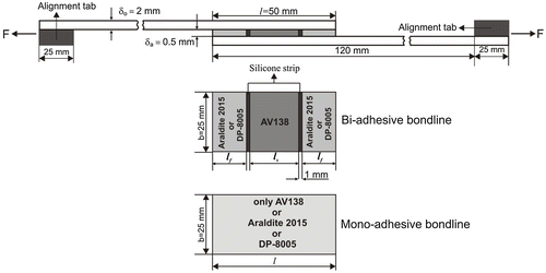
Geometry and dimensions of the mono and bi-adhesive joints are shown in Figure . The thicknesses of the adherends and adhesives are 2 and 0.5 mm, respectively. The total overlap length l, 2lf + ls, is 50 mm, where lf denotes both the length of the flexible and ductile adhesives and ls is the length of the stiff adhesive. The bond-length ratios of the bi-adhesive joint with Araldite 2015 (AV138 + 2015) varied as , while the bond-length ratio of the bi-adhesive joint with DP-8005 (AV138 + DP-8005) ξ = lf/ls = 0.5. Stiff adhesive was located in the middle of the bi-adhesive bondline length. Flexible or ductile adhesive was located at the ends of the bondline (see Figure ). In mono-adhesive joints, Araldite AV138, Araldite 2015 and DP-8005 adhesives were used as a single over the full length of the bondline.
Figure 1. Dimensions and geometries of mono and bi-adhesive joints.
Firstly, the selected overlap length of 50 mm is required to check whether the length causes adherend yielding or not. It is known that improperly selected overlap length reduces the joint strength by the adherend yielding. Global yielding criteria proposed by Adams [Citation27] can be used for defining the proper overlap length depending on the adhesive used. The failure load of the single-lap joint corresponding to the global yielding is:
(1)
where is the adhesive failure load and
is the shear yield strength of the adhesive. Here, b denotes the adherend width. Tensile stress that affected to adherend can be expressed as follows:
(2)
Here, δo denotes the adherend thickness. Adherend bending stress induced by the bending moment is given as follows:
(3)
Bending moment may be written in terms of bending moment factor (k) as [Citation27]
(4)
The total stress acting on adherends involves summation of tensile and bending stresses. Hence, using Equation (4) and summing Equations (2) and (3), we obtain the expression below that can be used to evaluate the maximum load carried by lap joint:
(5)
where σys is the yield strength of adherend. At low loads and short overlap lengths, bending moment factor can be taken equal to one.[Citation27] Rearranging Equation (5) by considering unit bending moment factor leads to equation given below:
(6)
For specimens having an overlap length/adherend thickness ratio of about 20, the variable k can be assumed as zero.[Citation27] In this case, rearranging Equation (5) by zero bending moment factor leads to the equation below:
(7)
Using the Global yielding criteria, adhesive failure loads with respect to the bondline length were calculated from Equation (1) and adherend failure loads from Equations (6) and (7), and results were plotted in Figure. . In Figure. , the horizontal line shows the failure load of DIN C75 adherend. Therefore, dashed lines related to adhesives should not exceed this horizontal line, for preventing the failure with adherend yielding. From the expression above, it is seen that the adherend will not yield if .
Figure 2. Predicted overlap length corresponding to adherend and adhesive yielding.
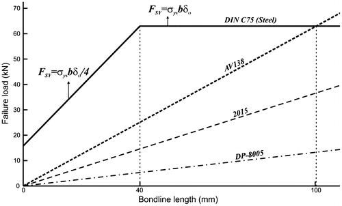
In addition, AV138 stiff adhesive among the adhesives used in this study have the highest shear yield strength. This means that the overlap length must be lower than approximately 100 mm (). As a result, one can say that the adherend will not yield for the chosen overlap length of 50 mm. Therefore, in this study, failures of the joints are controlled by the adhesive strength.
2.3. Joint manufacture
Each adherend was machined to 25 mm wide and 145 mm long, parallel to the bulk plate rolling direction. CNC laser cutting machine was used in order to guarantee geometrical dimensions of adherends.
Sandblasting surface treatment technique was applied to modify the topography of the adherend surface to increase wettability and remove oxide layer. Silica carbide sand of size 425–600 μm was used in modifying the topography of the adherend surface with the help of vacuum blasting machine. Silica carbide is extremely hard and sharp grain that is used in blasting of hard material surfaces.[Citation31] Blasting was continued until a matte view on the bonded surface was achieved.
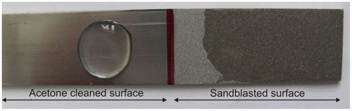
Distilled water drop test [Citation25] was performed in order to determine the influence of surface pretreatment on bonded surface wettability. As seen in Figure , distilled water was dropped on the acetone cleaned and sandblasted surfaces of steel adherend. As expected, it was seen that the wettability of bonded surface was improved substantially by modifying the surface with sandblasting technique.
Figure 3. Acetone cleaned and sandblasted-adherend surfaces.
In order to remove surface contaminant, sandblasted-adherend surfaces were cleaned again using an ultrasonic bath in liquid pure acetone for 8 min. When sandblasted adherends are left in atmosphere medium, oxide layer may occur again on the sandblasted surface. Attention was paid to complete bonding procedure in one hour to avoid this oxide layer.[Citation26] Roughness measurements of sandblasted surface were performed using the Marsurf PS1 Surface Roughness Instrument and roughness (Ra) was found to be 3.63 μm as an average value of three measurements.
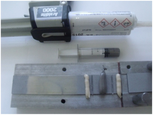
The whole mono and bi-adhesive lap joints were manufactured in a specially designed mold which has the fixed and movable parts to adjust the adhesive thickness (see Figure ). In preparing the bi-adhesive joints, silicone strip of 0.5 mm thickness and 1 mm wide was used to prevent mixing of adhesives with each other (see Figures and ). Silicone strip was fixed with cyanoacrylate adhesive on the adherend surface.
Figure 4. Mono and bi-adhesive joint manufacturing mold.
Adhesives were cured in a temperature controlled oven (Nüve FN 400). The cure temperature and time for mono and bi-adhesive joints are listed in Table .
Table 4. Cure temperature and time of the mono and bi-adhesive joints.[Citation2]
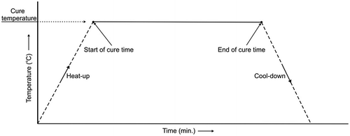
Thermometer with a thermocouple was used to monitor the change in the temperature throughout the adhesive curing. Temperature values were also recorded with respect to time. Figure shows adhesive curing cycles. Heat-up, cure time, and cool-down are the main stages of the curing period. In curing period, heat-up rate affects the final strength of the lap joint. In the case of lower heat-up rate, wettability of adherend-bonded surfaces with adhesive may be reduced because adhesive may cure before adhesive flow has occurred. If higher heat-up rate is used, large number of micro-voids are formed in the adhesive layer.[Citation27] In this study, the maximum heat-up rate of the oven was limited to the temperatures of 3–6 °C per minute. Cure time was started just after the adhesive reached the cure temperature (see Table and Figure ).
Figure 5. Curing periods for the adhesives.
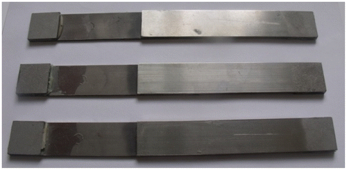
Single-lap joints were removed from the oven and cooled-down to room temperature at the end of the curing period of adhesive. Excessive adhesive around the bondline was removed by razor blade. Figure shows the prepared single-lap joints for tensile tests. At least three samples were prepared for testing mono and bi-adhesive joints.
Figure 6. Single lap joint specimens.
2.4. Tensile tests of mono and bi-adhesive single-lap joints
Before performing the tensile tests, the total thickness of the middle and ends of the overlap was measured by digital caliper to control the bondline thickness. The adhesive thickness was calculated by subtracting two adherend thicknesses from the measured total thickness. Tensile load was applied to mono and bi-adhesive joints with SHIMADZU AG-IS (50kN) test machine at 1 mm/min tensile speed. As seen in Figure , joints were mounted to the jaws of the test machine in a way to clamp the alignment tabs.
Figure 7. Tensile testing setup.
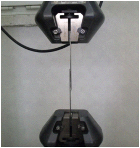
When mounting the joints to the jaws, attention was paid not to cause axial eccentricity that may lead to differences in failure load values. Tensile load was applied to the mono and bi-adhesive joints until rupture failure occurred. Loads and corresponding displacements were recorded throughout the tensile tests. Failure surfaces of bonded regions and deformation types of adherends and adhesives were examined. The tensile test results for mono and bi-adhesive joints are discussed in the next section.
3. Discussion of the experimental and analytical results
When the adherends were inspected after tensile test, it was seen that adherends show no plastic deformations due to bending effect and tensile load (see Figure ). Therefore, inspections confirm that predicted adherend yielding limit is not exceeded for the considered overlap length in this study (see Figure ).
Figure 8. Cohesive failure of bi-adhesive bondline.
Fracture surfaces of mono and bi-adhesive joints are shown in Figure . Figure (a)–(c) shows the failure surfaces of the mono-adhesive joints and Figure (d)–(g) shows the failure surfaces of the bi-adhesive joints. It was seen that there were adhesives on both bonded surfaces. This means that cohesive failure occurred inside mono and bi-adhesive bondlines. Therefore, cohesive failure shows that the surface preparation technique applied to adherend surfaces was sufficient and curing periods were proper.
Figure 9. Fracture surfaces of mono and bi-adhesive bondlines.
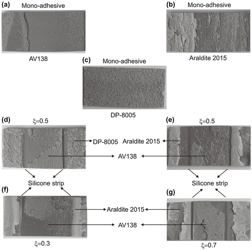
For mono-brittle adhesive, the failure is dominated by stress concentrations and the failure occurs in regions of maximum stress or strain concentration. A darker area can be observed on the fractured surfaces of the joints, which corresponds to catastrophic failure (very rapid damage growth). By observing the fractured surface of the 2015 adhesive, it can be noted that the stress-whitened areas spread inwards the overlap.[Citation31]
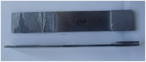
As seen in Figure (a), at the failure surface of the mono-AV138 adhesive bondline, crack started near the interface and then changed its propagation direction from the upper interface to the lower interface. It is known that this type of crack propagation was seen mainly in the brittle adhesives.[Citation2] Figure shows the schematic view of the joint with mono-AV138 adhesive crack propagation under tensile load.
Figure 10. Crack propagation of the joint with mono AV138 adhesive (see Figure 9(a)).
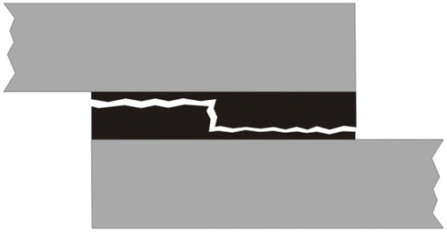
Figure (b) shows the failure surface of the mono-Araldite 2015 adhesive. Behavior of crack formation and propagation in ductile but relatively stiff and high-strength Araldite 2015 adhesive is similar to AV138 adhesive. However, when joint prepared with mono-acrylite adhesive DP-8005 was examined, unlike the other two epoxy adhesives, as seen in Figure (c), the formation and propagation of crack occurred along the mid-plane of the adhesive bondline. Failure behavior observed in DP-8005 is in accordance with general behavior reported in literature for high-ductility flexible adhesives.[Citation32]
Figure (d)–(g) shows the failure surfaces of bi-adhesive joints. As seen in Figure (d) and (e), the bi-adhesive joints (AV138 + DP-8005, AV138 + 2015) exhibit similar fracture surfaces with those in mono-adhesive joints. Failure behavior of AV138 adhesive shows different characteristics in the mono and bi-adhesive bondlines. Unlike the fracture behavior in the mono-AV138 adhesive bondline (see Figure (a)), it was seen that crack propagation direction didn’t change in the bi-adhesive bondline, in which AV138 is always in the middle of the bi-adhesive bondlines (Figure (d)–(g)). It is also reported by da Silva and Lopes that the failure pattern of the bi-adhesive joints is more complex to classify, but generally, the failure took place in the adhesive close to an interface.[Citation2]
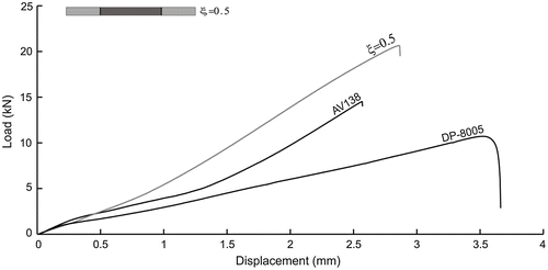
Figure shows the load-displacement curves for the mono-adhesive joints. It is seen that the highest failure load occurred in the Araldite 2015 mono-adhesive joint. The failure load of the Araldite 2015 mono-adhesive joint is about 1.4 times higher than that of the AV138 mono-adhesive joint. This can be explained by the fact that AV138 stiff adhesive have low plastic deformation capacity under tensile load and is sensitive to peel stress and structural faults.
Figure 11. Load–displacement curves of mono-adhesive joints.
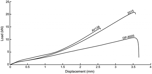
However, the load–displacement behavior of DP-8005 is different from the behaviors of the Araldite 2015 and AV138 adhesives. As seen in Figure , although failure load of the mono DP-8005 adhesive joint is lower than those of the mono AV138 and Araldite 2015 adhesive joints, the mono DP-8005 adhesive joint has a higher ductility and flexibility than the other two mono adhesives. As was pointed out by Banea and da Silva,[Citation33] failure behavior and failure load value for the mono DP-8005 adhesive joint are significant because of indicating that joint strength depends not only on ductility of the adhesive but also on level of shear strength of the adhesive.
Load–displacement curves of the bi-adhesive joints (AV138 + 2015) and mono-adhesive joints (AV138 and Araldite 2015) were given in the same figure (Figure ). It is clear from Figure that the failure loads of the bi-adhesive joints are higher than those of mono-adhesive joints. Bi-adhesive joint (AV138 + 2015) with the bond-length ratio of 0.5 gives the highest failure load among the other bi-adhesive joints with the bond-length ratios of 0.3 and 0.7.
Figure 12. Load–displacement curves of mono and bi-adhesive joints (AV138 + 2015).
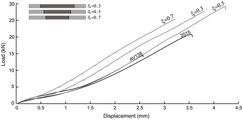
The bi-adhesive joint with the bond-length ratio of 0.5 gives 101.03% improvement in the joint failure load with respect to the mono AV138 joint and 40.51% improvement with respect to the mono Araldite 2015 joint. The value of failure load decreased with increasing the ductile adhesive length (see the ratio of 0.7). This showed that choosing proper bond-length ratio and adhesive combination (i.e. using sufficient amount of ductile adhesive in the bi-adhesive bondline such as ξ = 0.5 in our study) increased the failure load value in the bi-adhesive joint. This also showed that in a bi-adhesive joint, the strength of the bonded joint depends on the strength of the stiff adhesive. Therefore, selecting the appropriate bond-length ratio is crucial for bi-adhesive joints.
Figure shows the load–displacement curves of the bi-adhesive joint (AV138 + DP-8005) with the ratio of 0.5 and its mono counterparts. It can be seen that the combination of stiff and flexible adhesives gives higher failure load than its individual ones.
Figure 13. Load–displacement curves of mono and bi-adhesive joints (AV138 + DP-8005).
From the data of Figure , it is calculated that the bi-adhesive joint (AV138 + DP-8005) gives 42.32% improvement in the joint failure load with respect to the mono AV138 joint and 92.99% improvement with respect to the mono DP-8005 joint. Then, the experimental results showed a measurable increase in the failure load of the bi-adhesive joints compared with those in which mono adhesives were used over the full length of the bondline.
Lastly, experimental failure loads of the mono and bi-adhesive joints were compared with those obtained through analytical solutions. Global Yielding (G.Y) criterion [Citation27] was used to predict the failure load of mono-adhesive joint with ductile and flexible adhesives. The G.Y criterion assumes that lap joint reaches its maximum strength when the whole of the adhesive layer reaches its shear yield strength. However, this criterion is not appropriate for the mono-stiff adhesives. As an alternative method, Volkersen method can be used to determine the failure load of mono-stiff adhesive joints.[Citation34] According to Volkersen method, failure takes place when the shear strength of adhesive is exceeded at the ends of the overlap.
However, bi-adhesive bondline consists of a combination of stiff and flexible adhesives. Then, in the case of bi-adhesive joint, failure load can be predicted using Volkersen method associated with the G.Y criterion. Therefore, it is assumed that joint failure takes place when both adhesives reach their maximum strength. Failure load of mono-stiff adhesive in the bi-adhesive bondline can then be evaluated from the expression below [Citation2]:
(8)
(9)
Failure load of mono ductile or flexible adhesive in the bi-adhesive bondline can be predicted using the equation below (see also Equation (1)):(10)
where and
are the shear strength and the shear yield strength of the adhesives, respectively. Then, form Equations (8) and (10), failure load of bi-adhesive joint can be evaluated using the closed form expression below [Citation2]:
(11)
For detailed comparison, experimental and predicted failure loads of mono and bi-adhesive joints were tabulated in Table .
Table 5. Experimental and predicted failure loads.
As stated above, the G.Y criterion was used to predict the failure load of mono ductile and flexible adhesive joints, the Volkersen method was used to predict the failure load of mono-stiff adhesive joint. However, the failure load of the bi-adhesive joint was predicted with the use of the G.Y criterion and Volkersen method. Therefore, as expected, the Volkersen method predicts the failure load of mono-stiff AV138 joint more accurately than G.Y criterion (see Table ). For the mono ductile 2015 adhesive joint, failure load prediction of the G.Y criteria is more appropriate than that that of Volkersen method. However, it is interesting that the experimental failure load of mono flexible DP-8005 joint agrees well with those predicted from the both G.Y criterion and Volkersen model. From our previous studies [Citation20], it was seen that stress distributions of flexible adhesive is more uniform compared to the ductile and stiff adhesives, therefore, G.Y criterion and Volkersen model give close results for mono flexible joint in this study.
In addition, Fitton and Broughton reported that the average shear stress of the bi-adhesive bondline attained the shear strength of the stiff adhesive, which suggests that the joints had reached full shear capacity [35, p.266]. Fitton proposed that the shear strength capacity of a bi-adhesive joint can be predicted by
(12)
where s and f denote the quantities in the stiff and flexible adhesives, respectively. τmax is the shear strength capacity of the bi-adhesive joint. As and Af are the areas of the stiff and flexible adhesives in the bi-adhesive overlap region, respectively.[Citation20] Predicted shear strength capacities of the bi-adhesive joint were calculated using Equation (12) and tabulated in the right column of Table . (The shear strengths of the mono-adhesives were taken from Table ). The experimental average shear stress (τav) in the bi-adhesive lap joint was obtained by simply dividing the maximum experimental tensile load to full-overlap area. In Table , bi-adhesive configurations were presented as an order of .
Table 6. Experimental and predicted shear strengths.
It is seen from Table that comparisons between experimental and predicted shear strengths of the mono joints with 2015 and DP-8005 adhesives showed reasonable agreement. The bi-adhesive joint (AV138 + 2015) with ratio of 0.5 had the highest experimental average shear strength and failure load among all the other mono and bi-adhesive joints, and also reached the predicted shear strength. (In Table , this bond-length ratio was marked with a rectangular box.) The presence of the ductile adhesive at the ends reduces peel stress concentration, so stiff adhesive contribute its high shear strength capacity. Therefore, it may be said that the ratio of 0.5 can be the optimum possible ratio for the bi-adhesive joints.
From Table and , it was found that experimental failure load and experimental average shear strength of mono AV138 joint is much lower than that of mono ductile Araldite 2015 joint, although bulk properties of the stiff adhesive is much higher than that of the Araldite 2015 adhesive (see Table ). This can be explained by the deformation capacities of both adhesives. The adhesive Araldite 2015 has higher strain capacity to the failure than that of AV138. In the case of ductile adhesive, contribution of the middle part of the bi-adhesive bondline to load carrying increases due to the high strain capacity of the ductile adhesive. In addition, ductile adhesive is less sensitive to the peel stress when compared with stiff adhesive.
Also, it can be seen from Table and that, when experimental average shear strength and failure load values were compared, there was an insignificant difference between the mono Araldite 2015 adhesive joint and the bi-adhesive joint (AV138 + DP-8005). This result suggests that the selection of adhesives plays an important role in the bi-adhesive bondline. In the present study, it is more convenient to use low-cost mono ductile adhesive instead of bi-adhesive joint (AV138 + DP-8005), because of the cost of the DP-8005.
In addition, Bar graph was also used to illustrate a visual comparison between the experimental average shear strength and shear strength capacity (see Table ). In the Figure , horizontal dotted, dashed and dashed-double dotted lines represent the adhesive shear strength values (see Table ) and the vertical bars are the experimentally measured average shear strength values of mono and bi-adhesive joints (see Table ).
Figure 14. Experimental average shear stress and predicted shear strength of mono and bi-adhesive joints.
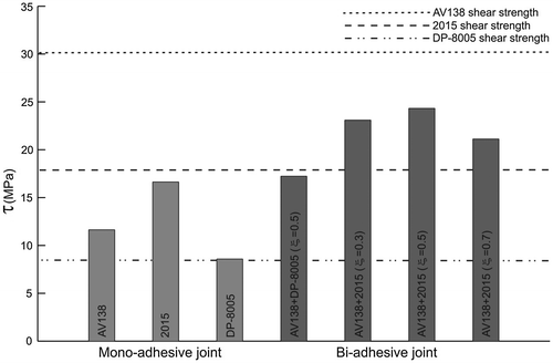
From Figure , it was concluded that experimental average shear strength of the mono-adhesive joints with Araldite 2015 and DP-8005 attained their maximum shear strength capacity. This suggests that the joints reached full shear capacity with increasing adhesive ductility. However, in the case of mono-adhesive joint with AV138, experimental average shear strength is well below its shear strength capacity. It is known that peel stress component is more dominant over the mono-stiff adhesive. Stiff adhesive AV138 is sensitive to peel stress and structural faults that form in its structure. Therefore, this explains why there is an apparent difference between experimental average shear strength and shear strength capacity.
Moreover, it is well known that the peel stress at the overlap ends of single-lap joint is definitely higher than that at the middle part of the joint due to bending moment effect. Peel stress effect is responsible for the instant failure and the joint strength decrease in mono-stiff adhesive joints. Then, in bi-adhesive bondline, peel stress effect on the stiff adhesive is minimized and thus shear stress effect is maximized. This means that when bi-adhesive bondline is used, the stiff adhesive can reach its high shear strength level, which increases joint strength.
As a result, returning again after these considerations to Figure , it can be easily seen from Figure that there is an insignificant difference between the experimental average shear strength values of the mono Araldite 2015 adhesive joint and the bi-adhesive joint (AV138 + DP-8005). This indicates that a mono ductile adhesive can be used alone instead of bi-adhesive formed with stiff and flexible adhesive (DP-8005). However, acrylate adhesive DP-8005 is quite expensive and sensitive to storage conditions when compared with the epoxy adhesives. It must be stored under 4 °C and expires in 6 months. For this type of adhesive, improper storage conditions extremely decrease the bond quality, which affect the joint strength. Therefore, it is more convenient to use low-cost epoxy adhesives instead of bi-adhesive joints (in this study, Av138 + DP-8005) with high-cost flexible adhesives.
4. Conclusions
The effect of the bi-adhesive bondline on the failure loads and shear strengths were studied experimentally. Various parameters were studied such as the bond-length ratio and adhesive types. The experimental failure loads and shear strengths of both mono and bi-adhesive joints were compared to those predicted by the analytical solutions. The main conclusions are as follows:
| (1) | Experimental failure load and average shear strength of mono AV138 adhesive joint is much lower than those of the mono ductile 2015 adhesive joint, although bulk properties of the stiff adhesive is much higher than that of the 2015 adhesive. This can be explained by the fact that ductile adhesives allow plasticization at the ends of the overlap region. In addition, ductile adhesive is less sensitive to the peel stress when compared with stiff adhesive. | ||||
| (2) | Considered bi-adhesive joints with two different adhesive combinations (AV138 + 2015, AV138 + DP-8005) give joint strengths higher than the joint strengths of the adhesives used individually, even if ductile adhesive has a joint strength higher than that of the stiff adhesive. This is the opposite of the findings reported by da Silva and Lopes.[Citation2] They stated that if the ductile adhesive has a joint strength lower than that of the brittle adhesive, a bi-adhesive joint with both adhesives gives a joint strength higher than the joint strength of the adhesives used individually. | ||||
| (3) | Bi-adhesive joints (AV138 + 2015) had the highest failure load and average shear strength among the other mono and bi-adhesive joints. The presence of the ductile adhesive at the ends reduces peel stress concentration, so stiff adhesive in the middle contribute its high shear strength capacity to the bi-adhesive joint. Bi-adhesive joint (AV138 + 2015) with the bond-length ratio of 0.5 reached the predicted shear strength and also got close to the shear strength of AV138. | ||||
| (4) | Bi-adhesive joint (AV138 + 2015) gives 101.03% improvement in joint failure load with respect to the mono AV138 joint and 40.51% improvement with respect to the mono 2015 joint. The value of failure load decreased with the increasing ductile adhesive length as for the ratio of 0.7. Bi-adhesive joint (AV138 + DP-8005) gives 42.32% improvement in joint failure load with respect to the mono AV138 joint and 92.99% improvement with respect to the mono DP8005 joint. These results suggest that the selection of adhesives plays an important role in the bi-adhesive bondline. | ||||
| (5) | When it comes to analytical results, for the mono-stiff adhesive joint, the Volkersen model predicted the failure load of AV138 more accurately than G.Y criteria. However, failure load prediction for the mono ductile adhesive 2015, G.Y criteria is more appropriate than Volkersen method. The experimental failure load of DP-8005 agrees well with those calculated from both G.Y criteria and Volkersen model. | ||||
This study showed that the bi-adhesive joint with ductile adhesive can attain the full shear strength of the stiff adhesive in the middle. It is known that ductile adhesive is an intermediate adhesive and its shear strength is between strengths of flexible and stiff adhesives. Using this type of adhesive at the ends allows the stiff adhesive to reach its full shear strength capacity. In contrast, using flexible adhesive with low-strength at the ends doesn’t allow the stiff adhesive to reach its full shear strength capacity. It can be therefore said as the last word that the state of being advantageous method of the bi-adhesive order over the classical mono-adhesive order is mainly related to adhesive properties at the ends.
Disclosure statement
No potential conflict of interest was reported by the authors.
References
- Özer H, Öz Ö. Three dimensional finite element analysis of bi-adhesively bonded double lap joint. Int J Adhes Adhes. 2012;37:50–55.
- da Silva LFM, Lopes MJCQ. Joint strength optimization by the mixed-adhesive technique. Int J Adhes Adhes. 2009;29:509–514.10.1016/j.ijadhadh.2008.09.009
- Pires I, Quintino L, Durodola JF, et al. Performance of bi-adhesive bonded aluminium lap joints. Int J Adhes Adhes. 2003;23:215–223.10.1016/S0143-7496(03)00024-1
- Fitton MD, Broughton JG. Variable modulus adhesives: an approach to optimised joint performance. Int J Adhes Adhes. 2005;25:329–336.10.1016/j.ijadhadh.2004.08.002
- Temiz Ş. Application of bi-adhesive in double-strap joints subjected to bending moment. J Adhes Sci Technol. 2006;20:1547–1560.10.1163/156856106778884262
- Pires I, Quintino L, Miranda RM. Numerical simulation of mono- and bi-adhesive aluminium lap joints. J Adhes Sci Technol. 2006;20:19–36.10.1163/156856106775212387
- da Silva LFM, Adams RD. Adhesive joints at high and low temperatures using similar and dissimilar adherends and dual adhesives. Int J Adhes Adhes. 2007;27:216–226.10.1016/j.ijadhadh.2006.04.002
- Bouiadjra BB, Fekirini H, Belhouari M, et al. Fracture energy for repaired cracks with bonded composite patch having two adhesive bands in aircraft structures. Comput Mater Sci. 2007;40:20–26.10.1016/j.commatsci.2006.10.016
- Kong F-R, You M, Zheng X-L. Three-dimensional finite element analysis of the stress distribution in bi-adhesive bonded joints. J Adhes. 2008;84:105–124.10.1080/00218460801952791
- Marques EAS, da Silva LFM. Joint strength optimization of adhesively bonded patches. J Adhes. 2008;84:915–934.10.1080/00218460802505275
- das Neves PJC, da Silva LFM, Adams RD. Analysis of mixed adhesive bonded joints part I: theoretical formulation. J Adhes Sci Technol. 2009;23:1–34.10.1163/156856108X336026
- das Neves PJC, da Silva LFM, Adams RD. Analysis of mixed adhesive bonded joints part II: parametric study. J Adhes Sci Technol. 2009;23: 35–61.10.1163/156856108X336035
- Kumar S, Pandey PC. Behaviour of bi-adhesive joints. J Adhes Sci Technol. 2010;24:1251–1281.10.1163/016942409X12561252291982
- Kumar S. Analysis of tubular adhesive joints with a functionally modulus graded bondline subjected to axial loads. Int J Adhes Adhes. 2009;29:785–795.10.1016/j.ijadhadh.2009.06.006
- Stapleton SE, Waas AM, Arnold SM. Functionally graded adhesives for composite joints. Int J Adhes Adhes. 2012;35:36–49.10.1016/j.ijadhadh.2011.11.010
- Bavi O, Bavi N, Shishesaz M. Geometrical optimization of the overlap in mixed adhesive lap joints. J Adhes. 2013;89:948–972.10.1080/00218464.2013.782813
- Akpinar S, Aydin MD, Özel A. A study on 3-D stress distributions in the bi-adhesively bonded T-joints. Appl Math Model. 2013;37:10220–10230.10.1016/j.apm.2013.06.008
- Carbas RJC, da Silva LFM, Madureira ML, et al. Modelling of functionally graded adhesive joints. J Adhes. 2014;90:698–716.10.1080/00218464.2013.834255
- Afkar A, Camari MN. Finite element analysis of mono- and bi-adhesively bonded functionally graded adherend. J Fail Anal Prev. 2014;14:253–258.10.1007/s11668-014-9790-x
- Öz Ö., Özer H. On the von Mises elastic stress evaluations in the bi-adhesive single lap joint: a numerical and analytical study. J Adhes Sci Technol. 2014;28:2133–2153.10.1080/01694243.2014.948110
- Özer H, Öz Ö. A comparative evaluation of numerical and analytical solutions to the bi-adhesive single-lap joint. Math Probl Eng 2014;Article ID 852872:1–16.
- Carbas RJC, da Silva LFM, Critchlow GW. Adhesively bonded functionally graded joints by induction heating. Int J Adhes Adhes. 2014;48:110–118.10.1016/j.ijadhadh.2013.09.045
- Kumar S, Khan MA. A shear-lag model for functionally graded adhesive anchors. Int J Adhes Adhes. 2016;68:317–325.10.1016/j.ijadhadh.2016.04.010
- da Silva LFM, Rodrigues TNSS, Figueiredo MAV, et al. Effect of Adhesive type and thickness on the lap shear strength. J Adhes. 2006;82:1091–1115.10.1080/00218460600948511
- Pinto AMG, Campilho RDSG, Mendes IR, et al. Numerical and experimental analysis of balanced and unbalanced adhesive single-lap joints between aluminium adherends. Int J Adhes Adhes. 2014;90:89–103.10.1080/00218464.2013.773258
- Pinto AMG, Magalhães AG, Campilho RDSG, et al. Single-lap joints of similar and dissimilar adherends bonded with an acrylic adhesive. J Adhes. 2009;85:351–376.10.1080/00218460902880313
- Dillard DA, Pocius AV. Adhesion science and engineering-1:The mechanics of adhesion. New York, NY: Elsevier; 2002.
- Ebnesajjad S. Handbook of adhesives and surface preparation: technology, applications and manufacturing. Oxford: Elsevier; 2011.
- Bresson G, Jumel J, Shanahan MER, et al. Strength of adhesively bonded joints under mixed axial and shear loading. Int J Adhes Adhes. 2012;35:27–35.10.1016/j.ijadhadh.2011.12.006
- Gower MRL, Broughton WR. Fractographic analysis of adhesive joints report no 11. Teddington, Middlesex: Centre for Materials Measurement & Technology, National Physical Laboratory; 1999.
- Davis M, Tomblin J. Best practice in adhesive-bonded structures and repairs technical report no DOT/FAA/AR-TN06/57. Virginia: National Technical Information Service (NTIS) Springfield; 2007.
- Banea MD, da Silva LFM, Campilho RDSG. The effect of adhesive thickness on the mechanical behavior of a structural polyurethane adhesive. J Adhes. 2015;91:331–346.10.1080/00218464.2014.903802
- Arenas JM, Alía C, Narbón JJ, et al. Considerations for the industrial application of structural adhesive joints in the aluminium–composite material bonding. Compos Part B: Eng. 2013;44:417–423.10.1016/j.compositesb.2012.04.026
- Banea MD, da Silva LFM. The effect of temperature on the mechanical properties of adhesives for the automotive industry. Proc Inst Mech Eng, Part L: J Mater Des App. 2010;224:51.
- da Silva LFM, Ferreira NMAJ, Richter-Trummer V, et al. Effect of grooves on the strength of adhesively bonded joints. Int J Adhes Adhes. 2010;30:735–743.10.1016/j.ijadhadh.2010.07.005
- da Silva LFM, Pirondi A, Öchsner A. Hybrid adhesive joints. Berlin: Springer; 2011.10.1007/978-3-642-16623-5