Abstract
A promising joining technology for thermoset CFRP is adhesive bonding. However, the mechanical performance is influenced negatively by contaminants, like release agents, as well as an excess of matrix in the top layer. In order to generate most suitable surface qualities prior to the bonding process, carbon fibre reinforced plastics are treated with different – UV (355 nm) and IR (1064 nm) – lasers. The results are compared to commonly applied grinding surface preparation. The preliminary results on surface properties, e.g. energy and topography point towards high levels of free surface energy, as well as new originated surface structures. After the bonding process mechanical tests are subsequently carried out in Mode II, to characterize the final joint by its tensile shear strength. Finally, the individual fracture behaviour is examined in post mortem analysis. The results indicate that it is possible to increase the tensile shear strength of the joints to a maximum, which equals the interlaminar shear strength of the CFRP-laminate. Therefore, ultrashort pulsed IR-laser techniques show the best reproducibility and the highest tensile shear strength. In addition, IR-laser treatment is expected to have the highest potential for later applications.
Introduction
As CFRP’s have an excellent weight to strength ratio, they are essential in nearly all new technology areas especially lightweight construction, e.g. aerospace industry. However, efficient lightweight construction make new strategies for joining inevitable. Bonding of CFRP’s exert increasing influence on all applications due to advantages, like lighter structural weight, lower fabrication costs and greater design flexibility. Structural joining techniques like riveting and bolting are used even if they damage the material because of the required holes and delamination and stress concentrations on these holes [Citation1].
Due to the manufacturing process, surfaces of CFRP are always contaminated with release agents and show a thick polymer layer (2–10 μm) on the top [Citation2]. These features cause an insufficient bonding behaviour. Thus, pre-treatment is crucial to completely remove the contaminants as well as excess matrix material in a reproducible, fast and easy way to give a clean and pre-activated surface [Citation3].
Different methods – e.g. by peel-ply [Citation4–7], grinding [Citation8], grid blasting [Citation6,8], plasma treatment [Citation6–8] as well as combinations thereof – to achieve clean and activated CFRP surfaces can be found in literature and are applied in industry [Citation9,10]. Using a peel-ply, which is laminated on top of the CFRP, promises a clean, activated surface. However, a thick epoxide layer which is contaminated with release agents remains [Citation11]. Next to peeling, the most common processes are mechanical strategies like grinding or grid blasting. They are easily applicable, but simultaneously hold the risks of low reproducibility, rapid tool wear as well as additional surface contamination. As a result, an additional cleaning process is usually required [Citation2,12]. A contact-less - and therefore related method to laser processing - is the treatment with atmospheric-pressure plasma. Generally a suitable cleaning and activation is achieved by this method, however some drawbacks like rapid aging [Citation13] and incomplete removal of fluorine based release agents [Citation8] increase difficulties for appliers.Footnote1
The work presented here covers different laser strategies: Firstly, a pre-treatment strategy using UV short wavelength laser radiation, which is extinct within a few micrometres beneath the matrix surface [Citation14]. This leads to photo induced depolymerisation reactions in the top surface layer of the thermoset CFRP matrix (binding energy of C–N single bonds 3.17 eV [Citation15]). The UV-laser removes exclusively the epoxide material without damaging the fibre. With this technique it is possible to establish in a single step a reproducible, clean and activated surface [Citation12,16,17]. Thus, contaminated and excess epoxide material can be removed from the surface without influencing respectively damaging adjacent layers of the laminate. Consequently, the bonding behaviour can be optimised [Citation18]. However, short pulse, high energy UV-based machine types are expensive [Citation19].
Therefore, a new concept using IR-laser radiation with pulse durations of a few nanoseconds was applied in this study. Due to high energy input into the absorbing carbon fibres, and – as a consequence – establishing of a wide heat affected zone in the surrounding laminate, there are risks like fibre breakages and thermally induced depolymerisation of the matrix material [Citation20,21].
In this work a comparison of untreated as well as grinded specimens with two parameter sets of UV-laser treatment and three different IR-laser settings respectively was drawn. To evaluate the effects of different treatment procedures, free surface energies as well as the final topographies of the pre-treated CFRPs were analysed and correlated with the tensile shear strength that was measured in single lap joints experiments. Finally, by means of light as well as scanning electronic microscopy the fracture patterns were examined to show the impact of the individual treatment strategies onto the fracture mechanics.
Experimental
For this work unidirectional fibre-epoxide prepregs were used. The stacking sequence was [0/45/90/−45]2s. The prepregs were made of Hexcel HexPly® M21 and Toray fibre T800S. The final laminates were stacked and cured – 180 °C, 7 bar, 2 h – by hot pressing at Hadeg GmbH at atmospheric pressure to give 2 mm thick plates with a final size of 200 × 300 mm². The test specimens were cut to final size according to DIN EN 1465 on a Struers Discotom-5 diamond cutoff saw.
For adhesive bonding, a two-component cold curing epoxide system of HP-Textiles EP-60 K was used. The resin and hardener were mixed in a stoichiometric ratio of 2:1. After bonding, the adhesive was cured for 24 h at room temperature and subsequently tempered in an oven at 60 °C for 16 h, to achieve the maximum tensile shear strength of the epoxide (tensile shear strength maximum 19 MPa measured on steel) [Citation22]. This epoxide adhesive has a Young’s Modulus in a range of 2–5 kN/mm² according to the supplier [Citation22]. The surface free energy of the liquid epoxide is 33 mN/m [Citation23].
The mechanically pre-treated CFRP-specimens were grinded automatically with a 220 grain size SiC-paper for 5 s without cooling agents using a Struers Rotopol (load: 30 N) in order to reveal reproducible results. Afterwards, the specimens were cleaned with acetone and dried subsequently.
For the UV-laser (DPSS λ = 355 nm by tripling the common IR-radiation, photon energy 3.46 eV) treatment, two sets of individual parameters were tested (see Table ). This laser type uses a Gaussian beam profile with a focal diameter of 35 μm. Frequencies and pulse lengths of 20 kHz / 10 ns (UV1) and respectively 60 kHz / 14 ns (UV2) were applied. The laser track distance was kept constant at 25 μm.
Table 1. UV- and IR-laser settings.
Table 2. Experimental data.
The IR-laser machining procedures were performed by using a DPSS laser (λ = 1064 nm). Pulse durations of 200 ns (IR1) and 30 ns (IR2) were applied at frequencies of 27 and 100 kHz respectively. A further setting (IR3) was a combination of IR1 and IR2. The IR-laser uses a flat top beam profile with a focus diameter of 104 μm.
For both laser treatment strategies the laser direction was kept perpendicular to fibre direction in order to minimize exposure times and therefore, heat input into the carbon fibres. Detailed parameter sets of the laser settings are listed in Table [Citation24].
Surface properties
The roughness values were determined at a ZeGage™ 3D optical profiler from Zemetrics Inc. in a non-contact, scanning white light interferometry experiment. The measurement area was 500 × 500 μm². In addition, the surface free energies were determined in a sessile droplet test – at a Kruess Goniometer – using the Owens–Kaelbe–Wendt–Rabel method [Citation25–27].
Shear tests and post-mortem analysis
The single lap tensile shear strength was determined according to DIN EN 1465:1995-01 [Citation28], using a Schenk RSA 100 universal test machine with a 100 kN load cell (displacement controlled at a cross head speed of 1.5 mm/min). The joining area measured 25 mm in length with an overlap of 12.5 mm. The roving orientation of the top layer is oriented in force direction (0°). In Figure , the specimen dimension is shown. For each trial five samples were tested.
Figure 1. Specimen (grey) geometry including glass fibre cap stripes (visible black) as well as bonding overlap (hatched right) (DIN EN ISO 1465, 2009) [Citation28].
![Figure 1. Specimen (grey) geometry including glass fibre cap stripes (visible black) as well as bonding overlap (hatched right) (DIN EN ISO 1465, 2009) [Citation28].](/cms/asset/43c9bfe5-5e3a-43cf-9d25-b2e3831aebb8/tast_a_1310695_f0001_b.gif)
Interlaminar shear strength of the composite was tested according DIN 65148:1986-11. Samples were made out of the same laminate but using unidirectional fibre stacks with orientation in force direction. The specimen dimension is shown in Figure . Six samples were tested and standard deviations are mentioned as individual error.
Figure 2. Specimen geometry for interlaminar shear strength test (DIN 65148, 1984) [Citation30].
![Figure 2. Specimen geometry for interlaminar shear strength test (DIN 65148, 1984) [Citation30].](/cms/asset/5a7060bd-56cd-48ca-a038-def7d4866d87/tast_a_1310695_f0002_b.gif)
For microscopic analysis the samples were fixed with Epofix embedding resin prepared with a polishing machine type Rotopol both from Struers Company. Microscopic investigations were performed using a Zeiss AxioPlan optical microscope and a scanning electronic microscope type Zeiss SEM LEO Gemini 1525 with a secondary emission detector and an acceleration voltage of 10 kV.
Results and discussion
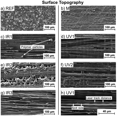
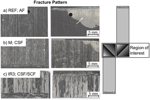
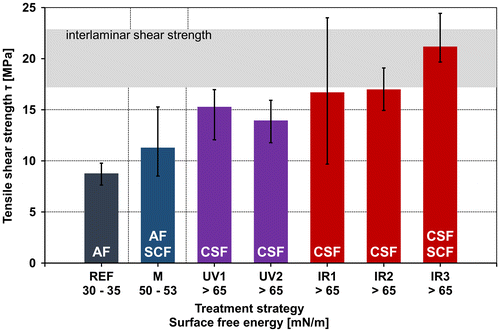
The untreated CFRP surface (REF) is characterized by its randomly shaped surface topology (see Figure (a), surface roughness Rz = 5.6 ± 0.8 μm, measured using white light interferometry) and its surface free energy (γ = 30.9 ± 3.2 mN/m). After joining, the single lap joint tests show a tensile shear strength of 8.8 MPa, which is approximately 45% of the interlaminar shear strength (ILSCFRp = 20.0 MPa) of the CFRP-laminate. The fractographic examination showed adhesive failure as main failure mode. The adhesive layer peeled off partly from both untreated substrates. This appears in bright colour in the respective images (see upper right corner marked with an arrow in Figure (a)).
Figure 3. SEM images of typical regions on differently treated CFRP surfaces, (a) untreated REF, (b) grinded M, (c) IR1 or (d) UV1 irradiation with increased intensity, (e) IR2 or (f) UV2 irradiation with less intensity as well as (g) IR3 irradiation with combined intensity for total matrix removal. 500x, SE-detector. Additionally, SEM image (h) showing a totally exposed fibre with characteristic narrowing in the size of the laser spot, appearing repetitively at the laser track distance, 1kx, SE-detector.

Figure 4. Typical fracture patterns as well as the mode of failure after different treating strategies, (a) REF, (b) M and (c) IR3 irradiation. 50×, bright field. ROI-Scheme of the facture patterns shown in a–c.

Mechanical grinding results in randomly shaped surfaces with typically lower roughness values in comparison with the untreated ones (Rz = 4.8 ± 0.9 μm, Figure (b), M). Fibres are exposed and damaged during the process, whereas other locally limited areas are still covered by the residues of the original top epoxide layer. This modified surface leads on the one hand to a different failure behaviour during mechanical testing and on the other hand to a higher dispersion of the final tensile shear strengths. Despite the automated machine controlled grinding procedure, no reproducible results in regard to mechanical properties were achieved. However, the tensile shear strengths increase by approximately 30% (11.3 MPa) in comparison to the untreated test specimens (see Figure ). Due to the heterogeneous surface quality, a mixture of two failure modes – adhesive (AF) and substrate near cohesive failures (SCF) – were detected in post mortem analyses (see Figure (b)) which is typical for this treatment process [Citation29]. Nevertheless, both the activation of the CFRP-laminate surface (γ = 51.6 ± 1.8 mN/m) and the clean surface are supposed to be responsible for the higher shear strength.
By using UV-laser radiation, large areas of the top epoxide layer are removed successfully (see Figures d/f, ‘UV’). Those specimens exhibit higher tensile shear strengths (UV1: 14 MPa) compared to mechanically grinded samples. A higher average power input (UV1), leads to more effective removal of the top epoxide layer. In addition, some surface near fibres show a decrease of the fibre thickness that occurs periodically corresponding to the laser track distance and shows a maximal width equal to the laser spot size (Figure (h)). This should be optimised in further investigations. Therefore, bonding directly to fibres is possible without an interfering epoxide. This results in a further increase of the tensile shear strength (UV2: 15.3 MPa). Post-mortem fracture analyses show trends towards substrate cohesive failure (CFRP delamination) as predominant mode of failure for both UV-laser pre-treatment strategies. This indicates that the substrate is damaged during both procedures and is becoming the weakest link. The determined CFRP interlaminar shear strength of 20.0 MPa could not be achieved in any SLJ test using UV-Laser treated CFRP laminates.
For the IR-laser based surface preparation, three different settings were used as described before (see also Table ). The intention by using high power laser radiation (IR1) was to remove efficiently large areas of epoxide material. The high-energy pulse passes the IR-transparent matrix and is absorbed at the IR-opaque carbon fibres. As a result a heat zone is formed that affects the surrounding matrix by thermal decomposition of the polymer as well as evaporation of the degradation products. However, SEM analysis showed remaining epoxide, loose polymer particles on top of exposed carbon fibres as well as fibre breakages (see Figure (c), ‘IR1’). The SLJ specimens prepared with setting IR1 exhibit a tensile shear strength of 16.7 MPa. The sum of the different surface interfering effects – particles, breakage, residual epoxide – leads to the highest dispersion calculated in this work. The loose particles as well as the residual epoxide matrix could hypothetically act as separating agents, which weakens the connection adhesive/substrate in an unpredictable manner and thus, causes a wide distribution of shear strength in this test series. However, there is in general less residual epoxide matrix (Figure (c)) in comparison to both UV treatment strategies (Figure (d) and (f)) and therefore, this increase leads to a better interaction between adhesive and load-bearing, free fibres.
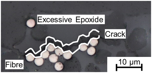
The specimens treated with a low average power (settings IR2, see Figure (e)) show a mixture of exposed fibres and quite large areas of remaining epoxide that was not removed due to the low energy input. Even if neither loose degraded particles nor damaged fibres could be detected, the tensile shear strength increases only slightly up to 17.0 MPa. Note, that the dispersion range decreases by a factor of approximately three compared to the IR1-treatment results. It seems to be a reasonable assumption, that the fibre-matrix-bonding is significantly reduced in those regions where thermally pre-damaged, remaining epoxide on the surface is observed – which negatively influences the shear strength of the whole bonding. Figure supports this assumption by exemplary showing a crack in between the excessive epoxide and the underlying C-fibres. However, in comparison to IR1, the occurrence of the residual epoxide is much more reproducible following the pattern of the laser scanning – which results in a comparable low scatter of the strength values.
Figure 5. Typical cross-section, optical image of a surface-near, intralayer crack – marked with white colour – showing damage in the matrix-fibre interface after IR2 pre-treatment of CFRP. 1kx, bright field.

Combining laser settings IR1 and three times IR2 to IR3 results in a smooth and homogeneous surface (see Figure (g)). The remaining particles on the surface after the IR1 treatment can be removed during the IR2 process. The single lap joints of test series IR3 show a low dispersion and the best bonding qualities with a shear strength of 21.2 MPa exceeding even slightly ILS of 20.0 MPa (DIN 65148, 1984) [Citation29]. The ILS gives a hint about the theoretical limit that can be expected in single lap joint experiments even though the intralaminar properties observed in the SLJ-experiments are not exactly comparable to the interlaminar behavior observed in the ILS experiments.
This reflects the importance of a homogeneous and clean surface in absence on any remaining particles or residual epoxide matrix. Having a defect free connection between fibre and adhesive the induced load can be transferred completely into the composite materials. As for the UV-laser treated samples, post-mortem fracture analyses of the IR-laser treated specimens reveal that the samples fail predominantly by substrate failure. The fracture surfaces show fibres which were pulled out of the substrate and remain in the adhesive layer (see Figure (c)).
In general, the surface energy strongly increases from non-treated to mechanical grinded, up to laser treated samples (see Figure ). Due to a spontaneous wetting of the laser treated surfaces by the test liquids, it was not possible to measure free surface energies exceeding 65 mN/m. As soon as the surface energy exceeds 33 mN/m, the surfaces are freely wetted by the adhesive applied for this study. This condition is reached after the grinding process. Thus, the effects of topography (e.g. smoothness and homogeneity) seem to be more important.
Conclusions
Laser based treatments of CFRP-laminates and combinations of different laser settings seem to be highly promising techniques to optimise the mechanical performance of a single lap joint. It was shown that a treatment previous to the bonding process increases the single lap joint tensile shear strength significantly (140% increase with a maximum value of 21.2 MPa compared to untreated samples). UV-radiation application enables a laser material ablation without damaging the fibres. This results in an increase of the tensile shear strength combined with comparably low dispersion. In contrast, short pulse IR-laser surface processing leads to material removal as well as to partially damaged fibres, but no heat degradation of the laminate. This is because of the short-pulsed laser source that allows a successful IR-laser treatment for the CFRP material. In particular, the combined application of different IR-laser settings produces homogeneous surfaces without a contamination by depolymerised material. In conclusion, IR-laser processing shows the best results in tensile shear strength, that demonstrates successfully the potential of the contact-less, cost efficient IR-laser treatment for industrial application.
Mechanical grinding as an alternative and widely used pre-treatment process improves the shear strength as well - but only about 30%. However, it is afflicted with a high dispersion in shear strength, compared to untreated surfaces.
In further investigations the described pre-treatment settings will be optimised. This will be the basis for CFRP treatment in combination of adhesive bonding with other lightweight materials. Further suitable settings for lightweight material pre-treatment using UV- and IR-radiation are under investigation.
Disclosure statement
No potential conflict of interest was reported by the authors.
Funding
This work was supported by the Ministry of Science, Research and the Arts Baden-Wuerttemberg (Germany).
Acknowledgement
Markus Schweizer is grateful for the opportunity to prepare his master thesis at the Institute for Material Research, Aalen. We are grateful to Joachim Albrecht for assistance with white light interferometry measurements.
Notes
1. Low-pressure plasma techniques show the same potential for a successful surface cleaning and activation, however are not suitable for wide and cross-industrial applications due to high and costly demands in facilities infrastructure.
References
- Liu DF, Tang YJ, Cong WL. A review of mechanical drilling for composite laminates. Compos Struct. 2012;94:1265–1279. [Internet] Available from: http://www.sciencedirect.com/science/article/pii/S0263822311004387.
- Banea MD, da Silva LFM. Adhesively bonded joints in composite materials: an overview. Proc Inst Mech Eng L: J Mater Des Appl. 2009;223:1–18.10.1243/14644207JMDA219
- Hart-Smith LJ. The design of repairable advanced composite structures. Douglas Paper 7550, SAE Aerospace Tech Conf, Long Beach CA; 14/17 Oct 1985 [cited 2015 Feb 20].
- Bénard Q, Fois M, Grisel M. Influence of fibre reinforcement and peel ply surface treatment towards adhesion of composite surfaces. Int J Adhes Adhes. 2005;25:404–409.10.1016/j.ijadhadh.2004.11.006
- Kanerva M, Saarela O. The peel ply surface treatment for adhesive bonding of composites: a review. Int J Adhes Adhes. 2013;43:60–69. Available from: http://www.sciencedirect.com/science/article/pii/S0143749613000158.10.1016/j.ijadhadh.2013.01.014
- Gude MR, Prolongo SG, Ureña A. Adhesive bonding of carbon fibre/epoxy laminates: correlation between surface and mechanical properties. Surf Coat Technol. 2012;207:602–607.10.1016/j.surfcoat.2012.07.085
- Wetzel M, Holtmannspötter J, Gudladt H-J, et al. Sensitivity of double cantilever beam test to surface contamination and surface pretreatment. Int J Adhes Adhes. 2013;46:114–121.10.1016/j.ijadhadh.2013.06.002
- Encinas N, Oakley BR, Belcher MA, et al. Surface modification of aircraft used composites for adhesive bonding. Int J Adhes Adhes. 2014;50:157–163. Available from: http://www.sciencedirect.com/science/article/pii/S0143749614000050.10.1016/j.ijadhadh.2014.01.004
- Chin JW, Wightman JP. Surface characterization and adhesive bonding of toughened bismaleimide composites. Compos A Appl Sci Manuf. 1996;27:419–428.10.1016/1359-835X(95)00064-9
- Hart-Smith LJ. A peel-type durability test coupon to assess interfaces in bonded, co-bonded, and co-cured composite structures. Int J Adhes Adhes. 1999;19:181–191.10.1016/S0143-7496(98)00033-5
- Holtmannspötter J, Czarnecki J, Wetzel M, et al. The use of peel ply as a method to create reproduceable but contaminated surfaces for structural adhesive bonding of carbon fiber reinforced plastics. J Adhes. 2013;89:96–110.10.1080/00218464.2012.731828
- Fischer F, Kreling S. Using excimer lasers to clean CFRP prior to adhesive bonding. Reinf Plast. 2013;57:43–46. [cited 2014 Apr 10].
- Köckritz T, Schiefer T, Jansen I, et al. Improving the bond strength at hybrid-yarn textile thermoplastic composites for high-technology applications by laser radiation. Int J Adhes Adhes. 2013;46:85–94.10.1016/j.ijadhadh.2013.06.004
- Fischer F, Kreling S, Jäschke P, et al. Laser surface pre-treatment of CFRP for adhesive bonding in consideration of the absorption behaviour. J Adhes. 2012;88:350–363.10.1080/00218464.2012.660042
- Haynes WM, Lide DR, Bruno TJ, editors. CRC handbook of chemistry and physics: a ready-reference book of chemical and physical data. 94th ed. Boca Raton, (FL): CRC Press; 2013.
- Bénard Q, Fois M, Grisel M, et al. Surface treatment of carbon/epoxy and glass/epoxy composites with an excimer laser beam. Int J Adhes Adhes. 2006;26:543–549. Available from: http://www.sciencedirect.com/science/article/pii/S0143749605001211.10.1016/j.ijadhadh.2005.07.008
- Fischer F, Kreling S, Dilger K. Surface structuring of CFRP by using modern excimer laser sources. Phys Procedia. 2012;39:154–160. Available from: http://www.sciencedirect.com/science/article/pii/S1875389212025527.10.1016/j.phpro.2012.10.025
- Völkermeyer F, Fischer F, Stute U, et al. LiM 2011 laser-based approach for bonded repair of carbon fiber reinforced plastics. Phys Procedia. 2011 [cited 2014 Dec 12];12:537–542.10.1016/j.phpro.2011.03.066
- Leibinger P. Die Lasertechnik von Morgen [Laser technology oftomorrow]. Interview by Laser Magazine. 2016
- Schmutzler H, Popp J, Büchter E, et al. Improvement of bonding strength of scarf-bonded carbon fibre/epoxy laminates by Nd:YAG laser surface activation. Compos A Appl Sci Manuf. 2014;67:123–130. Available from: http://www.sciencedirect.com/science/article/pii/S1359835X1400270X.10.1016/j.compositesa.2014.08.029
- Takahashi K, Tsukamoto M, Masuno S, et al. Heat conduction analysis of laser CFRP processing with IR and UV laser light. Compos A Appl Sci Manuf. 2016;84:114–122. Available from: http://www.sciencedirect.com/science/article/pii/S1359835X1500473X.10.1016/j.compositesa.2015.12.009
- HP Textiles. HP-E60 K: technical data sheet. 2011. p. 1–2.
- DIN Deutsches Institut für Normung e.V. DIN 55660:2011-3, Beschichtungsstoffe - Benetzbarkeit - Teil 3: Bestimmung der Oberflächenspannung von Flüssigkeiten mit der Methode des hängenden Tropfens [Paints and varnishes - Wettability - Part 3: Determination of the surface tension of liquids using the pendant drop method]. Berlin: Beuth Verlag. 2011.
- Trumpf. TruMark station 5000: originalbetriebsanleitung [Operating manual]. 2013 Aug 9.
- Owens DK, Wendt RC. Estimation of the surface free energy of polymers. J Appl Polym Sci. 1969;13:1741–1747. DOI:10.1002/app.1969.070130815.10.1002/app.1969.070130815
- Kaelble DH. Dispersion-polar surface tension properties of organic solids. J Adhes. 1970;2:66–81. DOI: 10.1080/0021846708544582.10.1080/0021846708544582
- Rabel W. Einige Aspekte der Benetzungstheorie und ihre Anwendung auf die Untersuchung und Veränderung der Oberflächeneigenschaften von Polymeren [Some aspects of the wetting theory and application on the investigation and change of polymer surface properties]. Farbe und Lack. 1971;77:997–1005.
- DIN Deutsches Institut für Normung e.V. DIN EN 1465, Klebstoffe – Bestimmung der Zugscherfestigkeit von Überlappungsklebungen [Adhesives - Determination of tensile lap-shear strength of bonded assemblies; German version EN 1465:2009]. Berlin: Beuth Verlag; 2009 [cited 2014 Feb 20].
- DIN Deutsches Institut für Normung e.V. DIN ISO 10365, Klebstoffe Bezeichnung der wichtigsten Bruchbilder [Adhesives - Designation of main failure pattern]. Berlin: Beuth Verlag; 1992 [cited 2014 Jun 27].
- DIN Deutsches Institut für Normung e.V. DIN 65148, Luft- und Raumfahrt; Prüfung von faserverstärkten Kunststoffen; Bestimmung der interlaminaren Scherfestigkeit im Zugversuch [Aerospace; testing of fibre-reinforced plastics; determination of interlaminar shear strength by tenside test]. Berlin: Beuth Verlag; 1986.

