
 ?Mathematical formulae have been encoded as MathML and are displayed in this HTML version using MathJax in order to improve their display. Uncheck the box to turn MathJax off. This feature requires Javascript. Click on a formula to zoom.
Abstract
This study develops a facile approach to fabricate adhesives consists of epoxy and cost-effective graphene platelets (GnPs). Morphology, mechanical properties, electrical and thermal conductivity, and adhesive toughness of epoxy/GnP nanocomposite were investigated. Significant improvements in mechanical properties of epoxy/GnP nanocomposites were achieved at low GnP loading of merely 0.5 vol%; for example, Young’s modulus, fracture toughness (K1C) and energy release rate (G1C) increased by 71%, 133% and 190%, respectively compared to neat epoxy. Percolation threshold of electrical conductivity is recorded at 0.58 vol% and thermal conductivity of 2.13 W m−1 K−1 at 6 vol% showing 4 folds enhancements. The lap shear strength of epoxy/GnP nanocomposite adhesive improved from 10.7 MPa for neat epoxy to 13.57 MPa at 0.375 vol% GnPs. The concluded results are superior to other composites or adhesives at similar fractions of fillers such as single-walled carbon nanotubes, multi-walled carbon nanotubes or graphene oxide. The study promises that GnPs are ideal candidate to achieve multifunctional epoxy adhesives.
1. Introduction
Adhesive bonding technology attracting more interest to replace mechanical joints in various engineering applications such as steel structures, and automotive and aerospace assemblies. Adhesive bonding advantages good insulation, superior damping, noise reduction and structural design flexibility which are challenging to achieve by other techniques [Citation1,Citation2]. Conductive adhesives promise rapid progress in electronic packaging in Advanced electronics where efficient heat dissipation and decent electric conductivity are essential.
Epoxy resins, as structural adhesives, are increasingly used in construction, mining, aerospace, and automotive industries owing to its high strength, low creep, very low cure shrinkage, excellent chemical and corrosion resistances, good processability, cost-effectiveness, and compatibility with wide range of substrates [Citation3,Citation4]. Despite of the aforementioned advantages of epoxy resin, it is brittle in nature and hence possesses poor crack resistance due to the tight three-dimensional crosslinked structures. Also, epoxy resins are inherently poor in electrical and thermal conductivity. Recently, there is an ongoing demand for advanced epoxy adhesives with improved mechanical and multifunctional properties to meet the requirements of particular applications such as modern electronics and particular parts in aerospace and automotive structures.
Adding fillers into the epoxy matrix is an effective method to improve its mechanical performance as well as functional properties. The most commonly used nanofillers are metal, silica [Citation5], rubber [Citation6], and carbon-based material [Citation4,Citation7,Citation8]. Metal nanoparticles have been widely used to reinforce epoxy adhesive due to their excellent electrical conductivity and stability [Citation9]. However, high filler loading is required to form a conductive network providing sufficient conductivity [Citation10]. Nanosilica attracted extensive research and development due to the high specific surface area and cost-effective fabrication; they have shown paramount reinforcing effect for adhesives on tensile properties. Meanwhile, the rubber nanoparticles were particularly used to toughen epoxy adhesive due to their soft nature. Nevertheless, silica and rubber particles are unable to achieve multi-functional preference of epoxy adhesives such as electrically and thermally conductive. Adding conductive fillers such as carbon allotropes (carbon nanotubes and graphene) into epoxy resins were studied widely by researchers due to their excellent mechanical properties, electrical and thermal conductivity, high aspect ratio and outstanding specific surface area.
Of carbon-based nanomaterials, graphene, one-dimensional, plate-like structure, is regarded as a promising reinforcing filler for the next generation of high-performance structural and multifunctional composites adhesives, due to its outstanding mechanical, electrical and thermal properties [Citation11]. However, producing flawless and high structural integrity monolayer of graphene layers is costly and challenging. Graphene platelets (GnPs) consisting of few layers of graphene, have received considerable interest as a promising alternative to develop high mechanically robust, electrical and thermal conductive and antistatic epoxy adhesives.
Soltannia et al. [Citation12] investigated the reinforcing effect of adding carbon nanotubes (CNT), graphene platelets (GnPs) and carbon nanofibers (CNF) into epoxy adhesive. They observed that epoxy/GnP adhesive joints showed high strength among the three carbon fillers. In another work, GnPs proved its effectiveness in enhancing joint strength by 49% at 0.5 wt% compared to 53% at 1 wt% of multi-walled carbon nanotubes (CNT) — joint strength at 0.5 wt% of CNT is not recorded in this study. Those studies and others support that graphene owns a promising potential to develop high strength adhesives. However, both studies lack of providing information about the physical properties of the fabricated epoxy composites such as electrical and thermal conductivity.
Our group developed a 3 nm GnPs in thickness by thermally expanding a commercial graphite intercalation compound and subsequently ultrasonicating the expanded product, which was used in this study. In comparison to graphene oxide and reduced graphene oxide, the yielded GnP features high structural integrity leading to high electrical conductivity of 1460 S·cm−1 [Citation13,Citation14]; range of thickness 3‒5 nm offering large surface area giving strong interface for stress, heat and electron transfer with epoxy matrix; epoxide groups existing on GnPs’ surface which can chemically react with the end-amine groups of organic molecules building strong interface for the nanocomposite adhesives; and most important cost-effectiveness (∼$20/kg).
In the current study, a facile approach was employed to fabricate epoxy/GnP nanocomposite adhesives achieving high mechanical performance, toughened and electrically and thermally conductive epoxy adhesive. Structure-property relations of epoxy/GnP nanocomposite are comprehensively investigated. The obtained nanocomposite adhesives of epoxy/GnP exhibited a significant enhancement in mechanical property, toughness, electrical and thermal conductivity at low content of GnPs, 0.5 vol%.
2. Experimental
2.1. Materials
The graphite intercalation compound (GIC, Asbury 1395) was kindly supplied by Asbury Carbons, Asbury, NJ, USA. Epoxy – diglycidyl ether of bisphenol A (WSR618, 184–200 g per equivalent, denoted E-51) – was ordered from Nantong Xingchen Synthetic Material. Jeffamine D400 (J400) hardener was supplied by Huntsman.
2.2. Fabrication of GnPs and epoxy nanocomposite adhesives
Preparation of GnPs is fully described elsewhere [Citation15]. Fabrication of epoxy/GnP nanocomposite adhesive is detailed as follow. GnPs were suspended in acetone in a covered metal container by stirring with a magnetic bar for 20 min, followed by ultrasonication for two hours below 25 °C, since low temperature promoted the exfoliation [Citation16]. Epoxy resin was added into the mixture by magnetic stirrer for 20 min to reach dissolution, followed by ultrasonication for 30 min. Using hot plate and magnetic stirring, acetone was evaporated at 70 °C. Vacuum-oven at 120 °C was used to remove any trapped bubbles and traces of acetone. The mixture was then cooled down to 30 °C, to add hardener– J400 via 2-min manually mixing with a wooden stick. This would produce epoxy/GnP nanocomposite adhesive.
2.3. Characterizations
2.3.1. Morphology
Scanning electron microscopy (SEM) was performed to examine the fracture surfaces (crack tip and propagation zone) of the CT specimens using (Philips XL30 Feg, SEM). First, the fractured surface was coated with a thin layer of platinum then observed under SEM at an accelerating voltage of 10 kV.
Structure of graphene platelets was examined by transmission electron microscopy (TEM) using Philips CM200, TEM at an accelerating voltage of 200 kV. The samples were prepared by suspending graphene sheets in tetrahydrofuran at 0.0004 wt% via 30 min sonication and then dropping the solution on 200-mesh copper grids, followed by drying. The bright-field high magnification TEM images were taken from a JEOL 2100 F microscopy operated at 120 kV.
2.3.2. Adhesive toughness and shear test
Toughness of neat epoxy and epoxy/GnP nanocomposite adhesives were measured by DCB testing. The adherends (150 × 10 × 10 mm) were fabricated according to ASTM: 3433-99 (2012) , ISO 25217:2009 and Ref [Citation17]. Copper shims of 0.3 mm in thickness were used to control the adhesive thickness and a non-sticky paper (40-μm thick) was employed to form initial precrack.
The epoxy/GnP nanocomposite adhesives were carefully degassed in a vacuum oven for 10 min to remove bubbles, followed by applying adhesives on the substrate’s surfaces. These two substrates were bonded by curing at 80 °C for 2 h, then 120 °C for 10 h. The lap-shear strength of epoxy adhesive and its nanocomposite adhesive were measured by tensile testing. The adherends (100 × 25 × 1.6 mm) of lap-shear test were fabricated according to ISO 4587:2003.
2.3.3. Compact tension and tensile testing
Rubber molds for compact tension (CT) and dumbbell samples were made from silicone rubber. After blending with hardener and degassing, the epoxy/GnP nanocomposites were poured into the molds, cured in a fan oven at 80 °C for 2 h then 120 °C for 10 h. Both sides of samples were polished by fine sand paper to suppress visible marks. Then the samples were thermally treated at 100 °C for 60 min to lessen any flaws resulted from polishing. Tensile testing was carried out at a cross-head speed of 0.5 mm/min at room temperature using an XIANGMIN machine. An extensometer (XM-DZSC001) was employed to capture accurate displacement data to measure Young’s modulus; all Young’s moduli were calculated at strain range 0.05–0.15%.
2.3.4. Glass transition temperature
Glass transition temperatures (Tg) were obtained using a dynamic mechanical analyzer (DMA) (DMA2980, TA Instruments, Inc, USA) at 1 Hz with a single cantilever clamp of a span 20 mm. DMA was recorded at temperature range 25‒100 °C; data was captured every 2 sec.
Table 1 Glass transition temperatures (Tg) of the nanocomposite adhesives at different GnP content.
2.3.5. Electrical and thermal conductivity
The electrical resistivity was measured using Agilent 4339B high resistivity meter equipped with a 16008B resistivity cell (two-point-probe) at room temperature. The measurement was conducted on the samples of 6.8 mm in thickness and 24 mm in diameter, in accordance to ASTM D257-99. The presented data is the average of at least three measurements.
Thermal conductivity (k) is defined as the time rate of steady state heat flow through a homogeneous material of unit area which is induced by a unit temperature gradient in a direction perpendicular to that unit area, W/mK.
(1)
(1)
where α, Cp and ρ are, respectively, thermal diffusivity, specific heat and density of samples, L–thickness of the specimen, ΔT–temperature change, q – heat flow rate.
Thermal resistance (R) is defined as the temperature difference, at steady state, between two defined surfaces of a material that creates a unit heat flow rate through a unit area, K·m2/W. As indicated in EquationEq. 2(2)
(2) , the value of the thermal resistance can be investigated by dividing the thickness over thermal conductivity of the specimen.
(2)
(2)
Thermal diffusivity was measured using laser-flash diffusivity instrument, LFA 447, NETZSCH. The laminated samples of size 12.7 mm diameter and ∼2 mm thickness was coated with a thin layer of fine graphite powder. The coated samples were left in a pan and lid of sapphire (Φ11 × 1.5 mm). The density was determined by automatic density analyser, ULTRAPYC 1200e, Quanta chrome Instruments.
3. Results and discussion
3.1. Morphology of graphene platelets (GnPs)
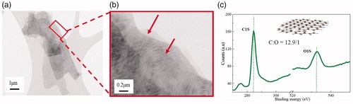
The TEM images of GnPs are shown in . Image (a) shows graphene as overlapped thin nanosheets with sizes of several micrometers; pieces of sheets are found sitting on lacey carbon support, and this clearly illustrates flake-like structure. A randomly selected area of the nanoplatelets without lacey-carbon support is magnified in . There were some overlapped structures located at the right side of the image (see red arrows); the most semi-transparent and featureless region likely possesses ultra-thin graphene sheets. The ordered lines (see white arrows) depicts that GnPs have intact crystalline structure giving high electrical conductivity. This highly crystal-lined structure is in accord with the XPS analysis (): The C/O ratio is nearly 12.9 for GnPs. Thus, our GnPs is a promising precursor for the fabrication of highly conductive nanocomposite adhesive. Furthermore, the wrinkled morphology of GnPs in is due to the flexibility of the 2 D nanosheets, which facilitates mechanical interlocking between the GnPs and epoxy matrix, leading to a significant improvement in mechanical performance.
Figure 1. (a), (b): TEM images of GnPs and (c): XPS of GnPs.
The exfoliation and dispersion of GnPs into epoxy resin are two crucial factors determining the mechanical and functional performances of the epoxy/GnP nanocomposite adhesives. presents TEM images of the 0.125 vol% epoxy/GnP nanocomposite adhesives. In , the light horizontal bands across the image could be a defect produced during the microtoming procedures. As marked by yellow arrows, cracks were initiated by microtoming within each cluster, indicating that clusters would act as defects posing a negative effect on the mechanical performance. When a part of a typical cluster was examined at higher magnification‒ it was found to consist of thin layers of graphene, a void and thick aggregates (red arrows).
Figure 2. TEM images of epoxy/GnP nanocomposite adhesives.
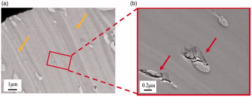
Generally, when phase transition happens during curing, (i) clusters of GnPs are formed although they may disperse uniformly prior to curing; (ii) the density and size of clusters would increase when nanoplatelets disperses as clusters at the end of curing, because clustering reduces the configurational entropy; this phenomenon is more or less similar to the phase separation in liquid-rubber- toughened epoxy adhesive [Citation5].
3.2. Mechanical properties
3.2.1. Young’s moduli and tensile strength
Young’s modulus and tensile strength of neat epoxy adhesive and its nanocomposite adhesives are shown in . It is obvious that the addition of GnPs into epoxy adhesive cause a significant influence on the mechanical behavior of the nanocomposite adhesive. With the increase of GnPs content, the Young’s moduli of the nanocomposite adhesives apparently exhibit a prominent enhancing trend (see ). For example, at 0.5 vol% GnP, the Young’s modulus reached a maximum value of 2.64 ± 0.2 GPa, demonstrating 82.07% improvement compared to the neat one proving successful reinforcement of nanocomposite adhesives by GnPs.
Figure 3. (a) Young’s modulus and (b) Tensile strength of the nanocomposite adhesives at various GnP contents.
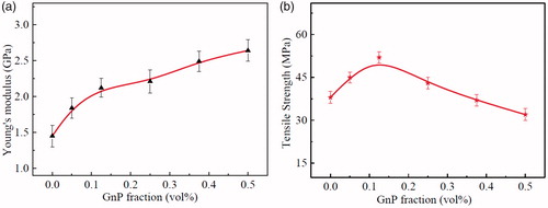
On the other hand, tensile strength of epoxy/GnP nanocomposite adhesives showed limited increase representing maximum value 52 ± 2.1 MPa at 0.125 vol% with an increment of 36.84%, then a slight decrease is observed. Uniform dispersion of GnPs in the host matrix is a key factor to obtain a strong interfacial interaction with the epoxy chains. Also, the wrinkled surface of GnPs results in strong mechanical interlocking between GnP and epoxy promoting the load transfer between them. These two factors take place at low volume fractions augmenting the mechanical performance of the epoxy. Further increase in GnPs content would produce overlapped sheets and clusters where stress concentration sites in nanocomposite [Citation18] are formed evidencing low tensile strength.
The introduction of rigid, two-dimensional nanolayers into a stiff matrix can produce toughening and stiffening effects, but it inevitably causes reduction in tensile strength. This is due to the weak van der Waal forces exist between individual sheets of the GnPs agglomerates [Citation19] leading to slipping between the shells will occur and thus lessening the strength of the nanocomposite adhesives. Also, most of the GnPs in epoxy matrix show significant curvature; upon loading, the nanoplatelets need to extend and rotate first along the tensile direction to maximize their improvements on the tensile strength. Accordingly, the relative reinforcement effect is limited for the nanocomposite adhesives with the wrinkled GnPs.
3.2.2. Lap shear strength
Single lap shear tests were carried out to characterize the mechanical behavior of the nanocomposite adhesives. Results obtained for lap shear strength are shown in , the lap shear strengths of the epoxy/GnP nanocomposite adhesives are higher than that of the neat epoxy adhesive. It steadily increases with the GnPs content until reaching a maximum value of 13.57 ± 0.61 MPa at 0.375 vol%, indicating ∼26% improvement compared to neat epoxy adhesive of 10.78 ± 0.5 MPa, and then start gradually to decline. At 0.5 vol% GnPs, the lap shear strength of the nanocomposite adhesives decreased, but was still above those of the neat epoxy adhesive. The high-volume fraction of GnPs causes a dilution phenomenon, i.e. the more GnPs vol%, the less epoxy resin vol%; this leads to a decrease in cross-linking density between epoxy molecules, lowering the rigidity of the nanocomposite. Moreover, high level of concentrations of GnPs tend to agglomerate in the host matrix providing a stress concentration locations where they act as defects in the epoxy matrix and thus reducing the nanocomposite mechanical resistance [Citation20,Citation21].
Figure 4. Lap shear strength of nanocomposite adhesives with different GnP content.
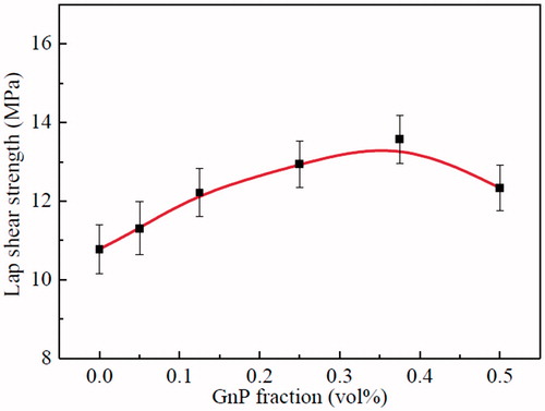
In summary, a suitable content of GnPs significantly improved the lap shear strength of the epoxy/GnP nanocomposite adhesives. It was assigned to the strong interfacial adhesion between GnPs and the epoxy resin leading to an efficient load transfer from the epoxy matrix to the nanofiller [Citation22,Citation23]. Additionally, the rigid, plate-like structure of GnPs embedded in epoxy matrix forms three-dimensional cross-linked network structure, enhancing the load transfer efficiency of nanocomposite adhesives. When a nanocomposite endures load, the rigid segments of GnPs produce lots of cracks, absorb the energy and improve lap shear strength of the epoxy/GnP nanocomposite adhesives. However, when the nanofiller content exceeds a critical level, it agglomerates in the nanocomposite adhesives causing stress concentration spots thus leading to a defect area in the epoxy matrix and causing a decline in its lap shear strength.
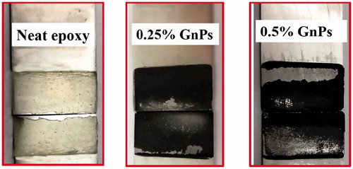
Failure type of epoxy/GnP nanocomposite adhesive joints were further investigated using digital imaging and surface analysis. presents digital images of adhesive joints after fracture of neat epoxy, 0.25 vol% and 0.5 vol% epoxy/GnP nanocomposites. The failure type for neat epoxy adhesive joints is 100% cohesive (within the adhesive) ‒. When graphene platelet is added to epoxy adhesives, type of failure changes with GnP fraction; at low GnP loading, the type of failure was cohesive indicating high interface between matrix and GnP; the middle image () presents that the fracture surface of 0.25 vol% showing adhesives on both substrates contains epoxy layer adhering to them. As the volume fraction of GnP increased, the type of failure progressed from cohesive to adhesive (at the interface between the adhesive and substrate) type. For the 0.5 vol.% GnP reinforced composite adhesive joints, a mixture of adhesive and cohesive failure was observed. The regions corresponding to cohesive failure was rough while the adhesively failed surfaces were smooth. In the smooth surface, the epoxy surface was flat and shiny and the corresponding region on the other substrate did not show any epoxy coating. Cohesively failed regions were observed in both substrates at the same location.
Figure 5. Mode of failure of neat epoxy and GnPs reinforced epoxy adhesive joints.
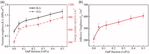
3.3. Toughness
Fracture toughness determines the energy required to propagate a sharp crack. It is considered as the most important property for structural materials such as epoxy adhesive. The results presented in proves that GnPs have a significant impact on the fracture toughness and fracture energy of the epoxy adhesive. Crack-opening tests on compact tension (CT) samples were performed to measure mode-I critical stress intensity factor (KIc, fracture toughness) and critical strain energy release rate (GIc, fracture energy) of the neat epoxy adhesive and its nanocomposite adhesives at various volume fractions of GnPs (see ). The values of KIc and G1c of the neat epoxy adhesive, 0.72 ± 0.1 MPa m1/2 and 309.8 ± 26 J.m−2, respectively, agrees with the published results [Citation5,Citation16]. For epoxy/GnP nanocomposite adhesives, a sharp increase of KIc and G1c was observed at 0.05 vol% of GnPs content, then a gradual enhancement was detected with the increase of GnPs. KIc and G1c reach their maximum values of 1.68 ± 0.13 MPa m1/2 and 896.24 ± 40 J.m−2 at 0.5 vol%, representing 133% and 190% improvements, respectively. represents the critical strain energy release rate G1c on double cantilever beam testing of the neat epoxy adhesive and nanocomposite adhesives following similar behavior illustrated in illustrating a maximum value of 406.24 ± 21 J.m−2 at 0.5 vol% of GnPs content as 93.65% improvement.
Figure 6. Toughness of the nanocomposite adhesives: (a) compact tension (CT); and (b) double cantilever beam testing (DCB).
The failure of the adhesive is a complicated process and involves the loss of structural integrity at microscopic and macroscopic levels under deformation. Due to inherent brittleness nature of the epoxy adhesives, catastrophic fractures may happen because of the lack of energy-absorbing during the crack propagation. Incorporating second phase into the crosslinked structure of epoxy proved to be an effective method to toughen epoxy resins. The existence of a second phase dissipates a significant amount of energy leading to high toughen epoxy. From , GnPs illustrate significant impact on the fracture toughness and fracture energy of the epoxy adhesive. The observed improvements in epoxy nanocomposite’s toughness would be due to: (i) GnPs forms stress concentrations sites to absorb fracture energy, (ii) GnPs serve as obstacles, stopping cracks propagation and thus consuming energy and (iii) the formation of crack tip blunting due to fracture of the GnPs and/or debonding of the epoxy matrix–GnPs interface consume more energy.
3.4. Morphology of CT-fracture surface and toughening mechanism
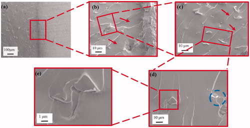
The fracture surface analysis of the compact tension (CT) specimen provides critical information to identify fracture mechanism of the nanocomposite adhesives. In and Citation8, respectively, the CT fracture surface of the 0.125 and 0.375 vol% epoxy/GnP nanocomposite adhesives were characterized by scanning electron microscope (SEM). Since the neat epoxy adhesive fracture surface is well known for being relatively smooth and mirror-like [Citation24–26], its SEM images are not presented in this study. By contrast, the epoxy/GnP nanocomposite adhesives shows a relatively rough fracture surface in . The crack tip magnified in shows number of river-lines (indicated by red arrows), — produced during razor blade tapping and usually observed on insufficient toughened fracture-surfaces — are found in front of plastic deformation zone [Citation27]. In , a broad whitening band are presented indicated by red arrows which proves a significant plastic deformation under loading. Whitening bands and lines refer to a stressed matrix corresponding to reduction in density, which are more sensitive to electrons and thus appear white; this demonstrates the existence of stress concentration and uneven fracture energy consumptions. In some clustered structures (blue circle) are found, and confirms the structure of a typical cluster.
Figure 7. Fracture surface of the 0.125 vol% epoxy/GnP nanocomposite adhesives.
contains the CT fracture surface of 0.375 vol% epoxy/GnP nanocomposite adhesives. Compared to the 0.125 vol% epoxy/GnP nanocomposite adhesives, the 0.375 vol% epoxy/GnP nanocomposite adhesive shows rougher fracture surface (). This implies larger amount of energy consumed during crack propagation, resulting in higher fracture toughness ().
Figure 8. Fracture surface of the 0.375 vol% epoxy/GnP nanocomposite adhesives.
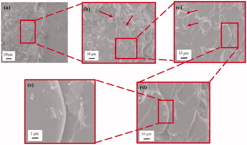
shows an overview of the fractography of the epoxy/GnP nanocomposite adhesives, notched region, crack tip, propagation region (deformation zone) and some geometric markings on the fracture surface. The “tail” morphology specifies the marking was created by crack pinning involving rigid GnPs particles. shows a magnified region in the instantly propagated crack zone at high magnification, made by razor tapping rather than loading. A few clusters were observed, as indicated by red arrows, consistent with the images in . From the high magnification image in , microcracks were also observed around the particles, indicating a debonding between GnPs and the epoxy matrix. The amount of crack pinning and microcracks increased with higher GnPs content where illustrated in and Citation8c. Because of the short interparticle distances, in the 0.375 vol% epoxy/GnP nanocomposite adhesives, the microcracks could be pinned before they were unified into the primary crack. The crack tip can also be pinned by the particulate obstacles, and thus the crack length increases. The crack deflection, pinning, and the coalescence of microcracks leads to a very rough surface. Tails are usually made at the back of particles before the unification of the pinned crack into the primary crack plane; this contributes to an increase in fracture line energy. Rigid fillers perform as stress concentrations spots; the confined stress field surrounding a GnP may form a microcrack zone and cause debonding between the GnPs and epoxy matrix. Therefore, a micro-void was formed around the particle in front of the crack tip opening, initiating a secondary crack propagation. This can be explained by a crack undergoing under a mixed mode; a tilt and twisting when encountering a rigid obstacle of the GnPs. Since GnPs are not chemically modified, the interface between GnPs and epoxy is relatively weak resulting in crack propagation along the interface line causing GnPs debonding.
From and the above-mentioned discussion, it is clear that at higher GnPs content, crack deflection and crack pinning increase accordingly, which result in an increase in fracture toughness.
3.5. Dynamic mechanical analysis
In this study, dynamic mechanical analysis (DMA) was employed to detect the influence of adding GnP on the storage modulus of the epoxy/GnP nanocomposite adhesives and determines their glass transition temperature (Tg). DMA also provides good knowledge about the interaction between the GnPs and the epoxy matrix. Although plethora studies reported an increase in Tg of epoxy upon incorporating sheet-like nanoclays [Citation28–30], this effect when GnPs on the epoxy/GnP nanocomposite adhesives remains infancy.
presents storage modulus and mechanical damping factor (tan δ) of epoxy/GnP nanocomposite adhesives as a function of temperature. In general, polymers have two distinct regions over a range of temperature: (i) glassy region at which temperature is below Tg and (ii) rubbery region where temperature is beyond Tg. Glass transition temperature (Tg) is the temperature at which higher molecular weight materials (polymers) transforms from glassy state to a viscous and rubbery state. It is directly related to the mechanical properties [Citation31] that the polymer (adhesive/plastic) exhibits at a certain temperature.
Figure 9. Dynamic mechanical analysis of epoxy/GnP nanocomposite adhesive (a) storage modulus and (b) Glass transition temperature at different GnP content.
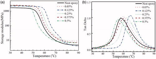
The storage modulus provides information about the elastic property (or energy stored) of a material. It is clearly noted that the inclusion of nanomaterials within the epoxy adhesive increases the storage modulus. The storage modulus values of epoxy adhesive reinforced with GnPs (0.05 and 0.125 vol% loading) are approx. 46% and 52% higher compared to neat epoxy adhesive in the glassy region (at 25 °C). This enhancement can be ascribed to the stiffness of GnPs which restrict the mobility of epoxy chains and thus eventually increase the modulus [Citation15].
From and , Tg of the epoxy nanocomposites keeps increasing until reaching its maximum value at 0.125 vol% then it drops. At 0.125 vol% of GnPs, Tg is increased by 10 °C recording an increase of 28% whilst at 0.5vol%, it dropped by 3 °C. The increment was caused by the good interaction between the epoxy matrix and GnPs blocking the epoxy chains mobility near the GnPs’ surface.
Upon adding more GnPs increases the Tg slightly decreases; due to two reasons (i) at high volume content, the inter-distance between GnPs fillers becomes narrow leading to filler agglomerations; and (ii) reduction of the epoxy matrix’s cross-linking density due to the interface interactions between the matrix and GnPs.
3.6. Electrical conductivity
Most of polymeric materials are inheritably poor in electrical conductivity (>10−9 S/cm). Electrical conductivity of ∼10−6 S/cm is sufficient for anti-static applications [Citation32]. Since epoxy adhesives are extensively used in aerospace and electronic industries, it is crucial to manipulate their electrical resistance/conductivity to meet the requirements of such applications. Conductive nanofillers, including metal-based particles and carbon-based materials are often used to improve the electrical conductivity of epoxy adhesives. The formation of electrically conductive epoxy/GnP nanocomposite adhesives not only depend on the electrical conductivity of GnPs, but also on the geometry, fractions and dispersion level of GnPs. The adopted GnPs in this study have outstanding electrical conductivity as well as number of surface functional groups such as epoxide groups which help GnPs to suspend in solvent.
illustrates the electrical conductivity of the nanocomposite adhesives as a function of GnP volume fraction. The nanocomposite adhesive shows a nonconductive nature at GnPs content ≤ 0.25 vol%. With more GnPs added, the inter-filler distance becomes smaller and at a certain volume fraction (percolation threshold) a filler-filler network is formed providing conductive paths for electron mobility, which breaks down the insulative nature of the epoxy adhesive. Further analysis is conducted by fitting the experimental data into the power law equation:
(3)
(3)
where σc is the nanocomposite conductivity, σf is the conductivity of the GnPs, φ is the GnPs vol%, φt is the percolation vol% and t is the critical exponent. The fitting line for the experimental results is shown in the insert in , resulting in t = 2.33 ± 0.21, which is slight lower than the experimental result (2.99 ± 0.2) in our previous report [Citation13].
Figure 10. Electrical conductivity of nanocomposite adhesive with different GnP content.
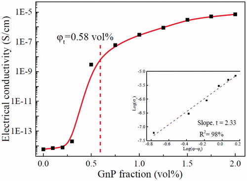
From , a percolation threshold was obtained at 0.58 vol% indicating the formation of global network of GnPs which facilitates conductive pathways for electron mobility recording a sudden rise in the electrical conductivity. Graphene platelets (GnPs) has high electrical conductivity (525 S/cm) which poses a remarkable effect on imparting conductivity into the nanocomposite adhesives. Adding to that, the high aspect ratio and descent dispersion quality of GnPs in epoxy matrix are crucial factors to determine low percolation threshold. At 2 vol%, the adhesive conductivity rises to 7 × 10⁻⁶ S/cm due to the 3 D network structure of GnPs demonstrating a novel nanocomposite adhesive possessing the potential for anti-static applications.
It is worth noting that the epoxy/GnP nanocomposite adhesives threshold is lower than those in previous studies [Citation33], the formation of an electrically conductive network at such a low threshold leads to the following conclusions: (i) these GnPs must uniformly disperse in the epoxy matrix and physically contact each other; (ii) GnPs must be sufficiently thin to counter the side effects of their poor through-plane conductivity; (iii) GnPs can replace single layer graphene in developing functional epoxy-based nanocomposite adhesives due to their high performance and cost-effectiveness.
3.7. Thermal conductivity
Thermal interface materials (TIMs) are important in the manufacture of electric and electronic devices, which requires mainly high thermal conductivity and suitable adhesion with metal substrates. Polymers with high thermal conductivity are of high interest in thermal management systems which can expand the plastics industry by partially replacing metals and ceramics in heat transfer devices and systems leading to energy and cost savings. Unfortunately, bulk polymers usually possess low thermal conductivity, ∼0.1‒0.3 Wm−1K−1, due to the presence of defects such as polymer chain ends, entanglements, random orientation, voids and impurities, etc. These defects act as phonon scattering sites for heat transfer. Introducing a high thermal conductive phase in a polymer matrix would enhance its thermal conductivity. GnPs consisting of few layers graphene, have intrinsically outstanding thermal conductivity [Citation34] and is widely used to improve the thermal properties of epoxy composites [Citation35]. The thermal conductivity of the nanocomposite adhesives is largely influenced by dispersion quality, loading amount and importantly the thermal resistance of the polymer-nanofiller interface [Citation36]. Since efficient heat propagation in GnPs is mainly due to diffusion of phonons, uniform dispersion and network of nanofillers in the polymer matrix contributes to the steady increase in thermal conductivity in the composite [Citation37].
records numerical values of thermal characteristics of neat epoxy and epoxy/GnP nanocomposite adhesives to determine the thermal conductivity using EquationEq. (1)(1)
(1) . As shown in , the thermal conductivity rises slowly with the GnPs at low vol% (less than 4 vol%); when the filling content is small, GnPs are not firmly connected each other leading to high Kapitza resistance (thermal boundary resistance) and hence overall low thermal conductivity. With increasing GnPs content, the interdistance between GnPs are very short forming a rigid and rich global 3-D network of GnPs leading to effective phonon transfer via lattice vibration. Thus, the rapid increase in thermal conductivity can be observed at ≥4 vol% of GnPs. In this study, the epoxy/GnP nanocomposite adhesives thermal conductive reached 2.13 W m−1 K−1 at 5.8 vol% recording more than 13 folds improvement compared to neat epoxy.
Figure 11. Thermal conductivity of nanocomposite adhesive with different GnP contents.
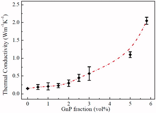
Table 2. Thermal properties of neat epoxy and its GnP-based nanocomposite adhesives.
From this study, GnPs is a promising filler to improve the epoxy adhesive thermal conductivity due to their intrinsic high thermal conductivity, and thin layer structure which can efficiently form 3-D thermal transport pathways in the epoxy matrix.
3.8. Comparison between carbon-based fillers
summarizes the mechanical properties, toughness, electrical and thermal conductivity of various carbon-based epoxy composites and composite adhesives reported in literature and the present research. In the current study, the epoxy/GnP nanocomposite adhesives have a relative high fracture toughness of 1.68 MPa.m0.5 and energy release rate of 896 J/m2 illustrating 77% and 201%, respectively, in contrast to ref [Citation49] where energy release rate was 96 J/m2 at 0.5 wt% of carbon nanofiber (CNF) ‒ fracture toughness was not reported. The lap shear strength of 12.34 MPa in the current study is far more than 7.5 MPa of the adhesives prepared at the same content of GnPs in ref [Citation52].
Table 3. A comparison of mechanical and functional performance of various carbon-based epoxy composites.
According to , few studies investigated adhesives featuring multifunctional performance including electrical and thermal conductivity. High electrical conductivity (e.g. ∼6 × 10⁻⁶ S/cm for 0.5 wt%, ∼2 × 10⁻⁴ S/cm for 1 wt%, and 3 × 10⁻³ S/cm for 2 wt%) were reported with relatively large amounts of SWCNT in epoxy, but with a decline in lap shear strength compared to the neat epoxy adhesive [Citation47]. Our study shows epoxy/GnP nanocomposite adhesives not only possess relatively high mechanical properties and toughness, but also feature obvious enhancement in lap shear strength, electrical and thermal conductivity at low content of GnPs.
Conclusions
Epoxy nanocomposite adhesives were fabricated with graphene platelets, GnPs (3–4 layers of graphene) as additives promoting their mechanical performance and electrical and thermal conductivity. An impressive improvement was obtained for nanocomposite adhesives by adding less than 0.5 vol% of GnPs; for example, at 0.125vol% of GnPs, 36.84% and 28% enhancements in tensile strength and glass transition temperature Tg, respectively; lap shear strength increased from 10.78 MPa for neat adhesive to 10.37 MPa for nanocomposite adhesive recording ∼26% improvement at 0.375 vol%; at 0.5 vol%, 133%, 190% and 71.7% improvements in K1C, G1C and Young’s modulus. Percolation threshold of the epoxy nanocomposite adhesive was determined at 0.58 vol% proving a continues a 3-D network of GnPs is formed; when 2 vol% GnPs were added into the epoxy adhesive, the electrical conductivity of was recorded as 10–5S/cm, nearly 1012 times compared to the neat epoxy adhesives. The thermal conductivity reaches 2.13 W m−1 K−1 at merely 6 vol% of GnPs. It is believed that the fabricated epoxy/GnP nanocomposite adhesives have potential applications in the modern advanced industry due to their high mechanical performance combined with electrical and thermal conductivity.
Disclosure statement
No potential conflict of interest was reported by the authors.
Additional information
Funding
Reference
- Christopher CJ, James MN, Patterson EA, et al. A quantitative evaluation of fatigue crack shielding forces using photoelasticity. Eng Fracture Mech. 2008;75:4190–4199.
- Mishra RS, Ma ZY. Friction stir welding and processing. Mater Sci Eng R. 2010;50:1–78.
- Zhou H, Liu HY, Zhou H, et al. On adhesive properties of nano-silica/epoxy bonded single-lap joints. Mater Des. 2016;95:212–218.
- Wernik JM, Meguid SA. On the mechanical characterization of carbon nanotube reinforced epoxy adhesives. Mater Des. 2014;59:19–32.
- Meng Q, Wang CH, Nasser S, et al. Nanosilica-toughened polymer adhesives. Mater Des. 2014;61:75–86.
- Meng Q, Araby S, Saber N, et al. Toughening polymer adhesives using nanosized elastomeric particles. J Mater Res. 2014;29:665–674.
- Meng Q, Kuan HC, Araby S, et al. Effect of interface modification on PMMA/graphene nanocomposites. J Mater Sci. 2014;49:5838–5849.
- Han S, Meng Q, Araby S, et al. Mechanical and electrical properties of graphene and carbon nanotube reinforced epoxy adhesives: experimental and numerical analysis. Compos Part A Appl Sci Manuf. 2019;120:116–126.
- Lu QS, Sun LH, Yang ZG, et al. Optimization on the thermal and tensile influencing factors of polyurethane-based polyester fabric composites. Compos Part A. 2010;41:997–1005.
- Kotthaus S, Gunther BH, Hang R, et al. Study of isotropically conductive bondings filled with aggregates of nano-sited Ag-particles. IEEE Trans Comp, Packag, Manufact Technol A. 1997;20:15–20.
- Novoselov KS, Geim AK, Morozov S, et al. Materials and methods: electric field effect in atomically thin carbon films. Science. 2004;306:666–669.
- Soltannia B, Taheri F. Influence of nano-reinforcement on the mechanical behavior of adhesively bonded single-lap joints subjected to static, quasi-static, and impact loading. J Adhes Sci Technol. 2015;29:424–442.
- Meng Q, Jin J, Wang R, et al. Processable 3-nm thick graphene platelets of high electrical conductivity and their epoxy composites. Nanotechnology. 2014;25:125707.
- Meng Q, Wu H, Zhao Z, et al. Free-standing, flexible, electrically conductive epoxy/graphene composite films. Compos Part A Appl Sci Manuf. 2017;92:42–50.
- Zaman I, Kuan H-C, Meng Q, et al. A facile approach to chemically modified graphene and its polymer nanocomposites. Adv Funct Mater. 2012;22:2735–2743.
- Zaman I, Phan TT, Kuan H-C, et al. Epoxy/graphene platelets nanocomposites with two levels of interface strength. Polymer. 2011;52:1603–1611.
- Meng Q, Zaman I, Hannam JR, et al. Improvement of adhesive toughness measurement. Polym Test. 2011;30:243–250.
- Deng H, Wu F, Chen L, et al. Enhanced interfacial interaction of epoxy nanocomposites with activated graphene nanosheets. J Appl Polym Sci. 2014;131:23.
- Chen Z, Lu H. Constructing sacrificial bonds and hidden lengths for ductile graphene/polyurethane elastomers with improved strength and toughness. J Mater Chem. 2012;22:12479.
- Lu S, Li S, Yu J, et al. Epoxy nanocomposites filled with thermotropic liquid crystalline epoxy grafted graphene oxide. Rsc Adv. 2013;3:8915–8923.
- Sriram V, Radhakrishnan G. Novel short-chain crosslinked cationomeric polyurethanes. Polym Bull. 2005;55:165–172.
- Li Y, Umer R, Samad YA, et al. The effect of the ultrasonication pre-treatment of graphene oxide (GO) on the mechanical properties of GO/polyvinyl alcohol composites. Carbon. 2013;55:321–327.
- Kong J, Tang Y, Zhang X, et al. Synergic effect of acrylate liquid rubber and bisphenol A on toughness of epoxy resins. Polym Bull. 2008;60:229–236.
- Le Q-H, Kuan H-C, Dai J-B, et al. Structure–property relations of 55 nm particle-toughened epoxy. Polymer. 2010;51:4867–4879.
- Ma J, Mo MS, Du XS, et al. Study of epoxy toughened by in situ formed rubber nanoparticles. J Appl Polym Sci. 2008;110:304–312.
- Kuan HC, Dai JB, Ma J. A reactive polymer for toughening epoxy resin. J Appl Polym Sci. 2010;115:3265–3272.
- Srivatsan TS. A review of: “Fractography: observing, measuring, and interpreting fracture surface topography, D. Hull. Mater Manuf Processes. 2009;24:1229–1230.
- Koerner H, Misra D, Tan A, et al. Montmorillonite-thermoset nanocomposites via cryo-compounding. Polymer. 2006;47:3426–3435.
- Guo B, Xing O, Cai C, et al. Exploitation of introducing of catalytic centers into layer galleries of layered silicates and related epoxy nanocomposites. I. Epoxy nanocomposites derived from montmorillonite modified with catalytic surfactant–bearing carboxyl groups. J Polym Sci B Polym Phys. 2004;42:1192–1198.
- And HL, Nutt S. Restricted relaxation in polymer nanocomposites near the glass transition. Macromolecules. 2003;36:4010–4016.
- Bashar MT, Sundararaj U, Mertiny P. Mode-I interlaminar fracture behaviour of nanoparticle modified epoxy/basalt fibre-reinforced laminates. Polym Test. 2013;32:402–412.
- Ma PC, Siddiqui NA, Marom G, et al. Dispersion and functionalization of carbon nanotubes for polymer-based nanocomposites: a review. Compos Part A. 2010;41:1345–1367.
- Zaman I, K HC, Dai J, et al. From carbon nanotubes and silicate layers to graphene platelets for polymer nanocomposites. Nanoscale. 2012;4:4578–4586.
- Song SH, Park KH, Kim BH, et al. Enhanced thermal conductivity of epoxy-graphene composites by using non-oxidized graphene flakes with non-covalent functionalization. Adv Mater. 2013;25:732–737.
- Prolongo SG, Moriche R, Jiménez-Suárez A, et al. Epoxy adhesives modified with graphene for thermal interface materials. J Adhes. 2014;90:835–847.
- Biercuk MJ, Llaguno MC, Radosavljevic M, et al. Carbon nanotube composites for thermal management. Appl Phys Lett. 2002;80:2767–2769.
- Yang SY, Ma CCM, Teng CC, et al. Effect of functionalized carbon nanotubes on the thermal conductivity of epoxy composites. Carbon. 2010;48:592–603.
- Sun L, Warren GL, O’Reilly JY, et al. Mechanical properties of surface-functionalized SWCNT/epoxy composites. Carbon. 2008;46:320–328.
- Wang Q, Dai J, Li W, et al. The effects of CNT alignment on electrical conductivity and mechanical properties of SWNT/epoxy nanocomposites. Compos Sci Technol. 2008;68:1644–1648.
- Balakrishnan A, Saha MC. Tensile fracture and thermal conductivity characterization of toughened epoxy/CNT nanocomposites. Mater Sci Eng A. 2011;528:906–913.
- Hernández-Pérez A, Avilés F, May-Pat A, et al. Effective properties of multiwalled carbon nanotube/epoxy composites using two different tubes. Compos Sci Technol. 2008;68:1422–1431.
- Hsiao MC, Ma CC, Chiang JC, et al. Thermally conductive and electrically insulating epoxy nanocomposites with thermally reduced graphene oxide-silica hybrid nanosheets. Nanoscale. 2013;5:5863–5871.
- Tang L-C, Wan Y-J, Yan D, et al. The effect of graphene dispersion on the mechanical properties of graphene/epoxy composites. Carbon. 2013;60:16–27.
- Bortz DR, Heras EG, Martin-Gullon I. Impressive Fatigue Life and Fracture Toughness Improvements in Graphene Oxide/Epoxy Composites. Macromolecules. 2012;45:238–245.
- Guadagno L, Sarno M, Vietri U, et al. Graphene-based structural adhesive to enhance adhesion performance. RSC Adv. 2015;5:27874–27886.
- Zeng C, Lu S, Xiao X, et al. Enhanced thermal and mechanical properties of epoxy composites by mixing noncovalently functionalized graphene sheets. Polym Bull. 2015;72:453–472.
- Jakubinek MB, Ashrafi B, Zhang Y, et al. Single-walled carbon nanotube–epoxy composites for structural and conductive aerospace adhesives. Compos Part B Eng. 2015;69:87–93.
- Sydlik SA, Lee J-H, Walish JJ, et al. Epoxy functionalized multi-walled carbon nanotubes for improved adhesives. Carbon. 2013;59:109–120.
- Gude MR, Prolongo SG, Gómez-del Río T, et al. Mode-I adhesive fracture energy of carbon fibre composite joints with nanoreinforced epoxy adhesives. Int J Adhesion and Adhes. 2011;31:695–703.
- Aradhana R, Mohanty S, Nayak SK. Comparison of mechanical, electrical and thermal properties in graphene oxide and reduced graphene oxide filled epoxy nanocomposite adhesives. Polymer. 2018;141:109–123.
- Salom C, Prolongo MG, Toribio A, et al. Mechanical properties and adhesive behavior of epoxy-graphene nanocomposites. Int J Adhes Adhes. 2018;84:119–125.
- Moriche R, Prolongo SG, Sánchez M, et al. Thermal conductivity and lap shear strength of GNP/epoxy nanocomposites adhesives. Int J Adhes Adhes. 2016;68:407–410.