Abstract
Purpose: Accurate monitoring of RF (radio frequency) power and phase is a key part of quality assurance (QA) for phased-array hyperthermia systems. In order to assess the steering capability of the BSD 2000 3D facility, an independent measurement system has been implemented, using a vector voltmeter (VVM) as the measuring device.
Methods: This paper describes the calibration of the RF signal paths from each of the 12 BSD Dodek amplifier outputs to the VVM instrument readout. Periodical network analyser measurements show that the uncertainty of the measured power using the VVM system is <4% for all channels, while the uncertainty of the phase measurements is <0.3°. The values are comparable to those reported for similar monitoring systems and are considered adequate for monitoring of the BSD Dodek steering parameters.
Results: Using the VVM system to investigate the accuracy of the BSD Dodek amplifier power and phase control, systematic differences were observed between the requested and the measured power for all channels: At a requested power level of 25 W per channel, the measured power level was on average 15% lower than nominal, whereas at 100 W it was nearly 20% higher. It was also observed that the absolute phase values are nearly 30° higher at 25 W per channel than at power levels ≥50 W per channel. Under certain circumstances, these issues may reduce target steering accuracy for the BSD 2000 3D system; on the other hand, the Dodek power and phase control stability is found to be acceptable.
Conclusions: The results emphasize the need for accurate, independent online power and phase QA during regional hyperthermia treatments using phased array systems.
Introduction
At Haukeland University Hospital, regional hyperthermia treatments of tumours in the pelvic area, the abdomen and the (lower) extremities are performed using the BSD 2000-3D system (BSD Medical Corporation, Salt Lake City, USA). Heating of tumours is accomplished by depositing energy using the Sigma 60 and Sigma Eye phased array applicators, which have four and 12 pairs of antennae, respectively. The antenna arrangement of the Sigma Eye applicator allows for three-dimensional energy deposition steering, i.e. in the cranial-caudal direction as well as in the anterior-posterior and lateral directions, while the Sigma 60 is limited to two-dimensional energy deposition steering.
In these phased array applicators, the energy deposition pattern is formed by interference between the electromagnetic fields generated by the different antennae, and the position and extent of the pattern can be manipulated through changing the relative phase and power of the signals fed to the different antenna pairs. Therefore, the precision and stability of the energy deposition in the target object—and hence of the heating pattern—is a function of the accuracy of the steering parameters of the heating system, i.e. its power and phase characteristics. Consequently, independent monitoring of the power and phase properties of the signals fed to the phased array is important in quality assurance for regional hyperthermia.
Based on this insight, Hornsleth et al. Citation[1] introduced the use of the VVM instrument as an independent power and phase measuring device and found a significant discrepancy between the requested steering parameters to the BSD 2000 system and the power and phase values measured using the VVM. Subsequently, the use of online power and phase monitoring systems have been encouraged by the ESHO (European Society for Hyperthermic Oncology) Citation[2] and the design and use of a 4-channel monitoring system for the BSD 2000 have been described in Gromoll et al. Citation[3] and Lamprecht et al. Citation[4].
More recently, the development of a VVM based power and phase QA facility for the BSD 2000 3D system has been reported by Lee et al. Citation[5]. Their measurement system, which is built with ‘off-the-shelf ’ components, is reported to be stable and within the required accuracy for assessment of the BSD 2000 3D system steering parameters.
Thus, after commissioning a BSD 2000 3D facility at our institution and considering the increased steering ‘degrees of freedom’ available for this 12-channel system, it was decided to develop an external power and phase measurement set-up for monitoring the stability and accuracy of the energy deposition steering parameters. Based on the design suggested by Hornsleth et al. Citation[1] it utilizes a VVM as the independent power and phase measuring device, using a set-up similar to that developed by Lee et al. Citation[5].
This paper reports on the characterization of the implemented VVM system in terms of power and phase stability and accuracy. Subsequently, the VVM system has been used to investigate the performance of the power and phase control of the BSD 2000 3D facility.
Materials and methods
In order to facilitate independent, on-line monitoring of the power and phase characteristics of each of the 12 RF outputs of the BSD Dodek amplifier, a VVM-based measurement system has been built. A schematic overview of the system is shown in .
Figure 1. Schematic overview of the VVM based measurement system and its interaction with the BSD system.
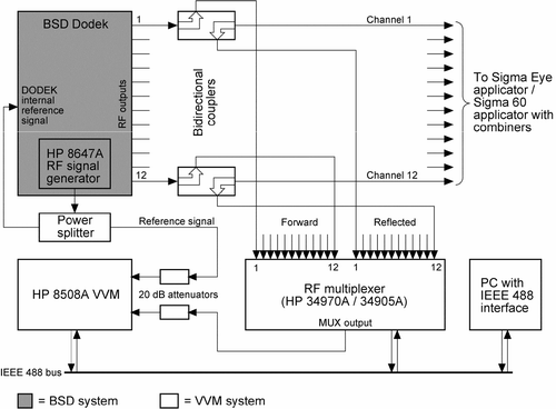
The VVM-system interacts with the Dodek at two points. First, directional couplers are connected at each of the 12 Dodek outputs in order to provide low-level measurement signals proportional to the forward and reflected components appearing at the Dodek outputs. The couplers have a minimal influence (which would also be nearly identical for all channels) on the phase and power of the signals fed to the applicator, so as not to interfere with the normal operation of the BSD system.
Secondly, a splitter is inserted into the amplifier reference signal path, between the HP 8647A signal generator, which is an integral part of the Dodek, and the control and PLL (phase-locked-loop) circuitry of the system. This is to provide a reference signal for the VVM phase measurement. The insertion of the splitter reduces the Dodek reference signal by 3 dB, but this does not interfere with the operation of the amplifier, whose phase and power control is performed at a later stage.
The reference signal is connected to one input of the VVM via a 20 dB attenuator, whereas the forward and reflected signals from the 12 directional couplers are connected to an RF multiplexer switch, the output of which is connected (also via a 20 dB attenuator) to the other input of the VVM, which only has a single pair of inputs. The VVM and RF multiplexer switch set-up implies use of additional signal cabling, which must be compensated for by using initial calibration measurements.
VVM operation and data readout, as well as multiplexer operation, is performed automatically from a PC, using the IEEE 488 instrument interface protocol, and controlled by software developed using the LabVIEW® tool from National Instruments Corporation (Austin, USA). The software allows for power and phase measurements either for a single amplifier channel or for a group of channels.
A complete list of the equipment used for the VVM system is shown in .
Table I. Equipment used in the on-line phase and power measuring system.
Power and phase calibration
In order to ensure accurate phase and power measurements at the Dodek outputs using the VVM system, it is necessary to characterize the signal paths from each directional coupler input, via its forward and reflected signal outputs and through cabling and multiplexer switches up to the VVM input. Specifically, the power attenuation and phase shift of all relevant signal paths should be determined; this has been done using a Hewlett Packard (Agilent) HP4395A network analyser with an HP 87511A S-parameter test set. Measurements have been performed for the 60–140 MHz frequency range, which encompasses the operational frequencies of the applicators used with the Dodek, i.e. 100 MHz for the Sigma Eye applicator and 85 MHz for the Sigma 60 applicator.
This procedure has been performed periodically in order to investigate the stability of the coupler–cabling–multiplexer network, as well as to obtain uncertainty estimates of the power and phase measurements performed using the VVM measurement system. For each channel, the arithmetic mean of the periodic measurements have been used to find the attenuation and phase shift calibration values. Furthermore, in order to quantify the measurement uncertainty for the power attenuation and phase shift of the individual signal paths from the amplifier output to the VVM, the standard deviation of the arithmetic mean of the periodic network analyser measurements has been used, which is the standard deviation of the n individual measurements divided by .
Finally, when estimating the total measurement uncertainty of the VVM system, it is also necessary to consider the measurement uncertainty of the VVM itself, in addition to the uncertainty of the attenuation and phase shift calibration of the coupler–cabling–multiplexer network. Thus, phase and power measurement uncertainties for the VVM have been found in its product specifications and have been taken into account when calculating the overall phase and power measurement uncertainties.
BSD Dodek performance evaluated using the VVM system
After having established power and phase shift calibration values and measurement uncertainties for all channels of the VVM system, it is possible to investigate the performance of the BSD Dodek 12-channel RF amplifier. Because the BSD system offers individual phase and power control of all 12 channels, a multitude of different parameter settings can be investigated. In this work, the investigation was mainly concerned with the accuracy and stability of the BSD power control system at different power levels. At the same time, the phase values were also monitored, in order to check for any power-dependent phase effects.
By operating the multiplexer such that one channel is selected all the time (instead of selecting all channels sequentially), the measurement sampling rate can be increased and possible transient effects can be observed. This was done for all 12 channels at 100 MHz, using nominal power settings from 20–100 W in 20 W increments. Each power setting was kept stable for 5 min with a phase target setting of (0, 0). The VVM system measurement rate during each run was two samples per second. Finally, the phase of each channel was measured as the BSD control software phase offset parameter was changed in 5° increments from 0–60°. During all the single-channel measurements, the channel under investigation was terminated in a 50 Ω high-power dummy load.
Results
Power and phase calibration from the Dodek amplifier to the VVM
Over a period of 2 months, the signal paths from the amplifier outputs (via directional couplers and switches) to the VVM were monitored on a (near-) weekly basis using a network analyser. A total of seven network analyser measurement series of the entire set of 12 channels were performed, at an ambient temperature of ∼22°C. The measurements were done in the frequency range of 60–140 MHz and an averaging factor of 16 (i.e. average of 16 single measurements) was used. The arithmetic mean of the measured signal attenuation and phase shift of the forward signal path from the amplifier output to the VVM (but not including the 20 dB attenuator at the VVM input) was then computed.
The average attenuation of the forward signal path (excluding the 20 dB attenuator) ranges from ∼−38 dB at 60 MHz to ∼−32 dB at 140 MHz. The overall behaviour is similar for all channels (all channels within 0.6 dB at 60 MHz and within 1.0 dB at 140 MHz), but as a group, the values for channels 1–8 are ∼0.3 dB lower than those of channels 9–12 at 60 MHz and about 0.5 dB lower at 140 MHz. This is expected, because the former group of channels (1–8) is connected across an extra level of multiplexer switches (and associated extra cabling) compared to the latter group (9–12), thus introducing a slight additional attenuation of the signal. Similarly, due to the added electrical length of the extra switch level and cabling, the average phase shift at any given frequency is larger for channels 1–8 than for channels 9–12 and it also changes more rapidly with frequency for the former group of channels.
VVM system measurement uncertainty
The estimated standard deviations of the means of the attenuation of the forward signal path range from ∼0.04–0.15 dB for the different channels, whereas those of the reflected signal path range from ∼0.02–0.11 dB. There is no significant variation of the values with frequency; numerical values for all 12 channels at 100 MHz are shown in . The estimated standard deviations of the mean of the phase measurements for the forward signal path range from 0.05–0.25° overall and from 0.07–0.21° at 100 MHz, see ; the variation with frequency is insignificant.
Table II. Power measurement uncertainty overview for VVM system at 100 MHz.
Table III. Phase measurement uncertainty overview for VVM system at 100 MHz.
After estimating the uncertainty related to the power and phase calibration of the forward and reflected measurement signal paths by computing the standard deviations of the attenuation and phase averages, the power and phase measurement uncertainties of the VVM must be taken into account. The VVM accuracy for a measurement parameter is specified by the manufacturer in terms of an error band h, i.e. for a given input value, a single measurement will be within ±h of the true value Citation[6]. As such, the measured variable is described by a rectangular distribution function and the variance for this type of distribution is given by h2/ Citation[7], Citation[8].
However, in its default mode of operation (which is used in this work), the VVM averages 32 subsequent readings internally to provide a measurement, thus reducing the standard deviation by a factor of compared to that of a single reading. When averaging n variables, each governed by a rectangular distribution, a normal (Gaussian) distribution is approached for the average value as the value of n is increased. Thus, it is a reasonable approximation to assume that the averaged power and phase measurement values from the VVM follow normal distributions.
Hence, assuming that the attenuation and phase shift measurements made using the network analyser also follow normal distributions, it is appropriate to estimate the total power and phase measurement uncertainties (1 SD) asand
respectively.
The term σAttenuation in Equation 1 represents the uncertainty contribution from the network analyser attenuation measurements, whereas the second and third terms represent the absolute accuracy vs. input level and the amplitude accuracy vs. frequency contributions from the VVM power measurement uncertainty. For the coupler–cabling–switch–attenuator configuration used and at 100 MHz frequency, the signal level at the VVM input lies approximately in the −12 to −3 dBm range for amplifier output power in the 20–100 W range. In this case, for a single readout, the absolute accuracy is ±0.3 dB and the amplitude accuracy is ±0.4 dB at 100 MHz, when specified in terms of error bands (see above) Citation[6], while the corresponding standard deviation values (again for a single readout) are 0.173 dB and 0.231 dB, respectively. When taking the VVM internal averaging into account, the resulting contributions (1 SD) to the overall power measurement uncertainty from the VVM absolute and amplitude uncertainties are 0.032 dB and 0.043 dB, respectively.
The estimated overall forward and reflected power measurement uncertainties at 100 MHz (which is the operational frequency of the BSD Sigma Eye applicator) are shown in , for all channels of the VVM system, along with the contributions from the measurement signal paths and the VVM measurement accuracy.
It is also of some interest to determine the uncertainty with which the combined total forward power of all 12 channels may be estimated: Using the forward power measurement uncertainties from and assuming that the forward power is uniformly distributed between all 12 channels, it is found that the uncertainty of the combined total power estimate is 0.7%.
As for the total phase measurement uncertainty, the σPhase shift term in Equation 2 represents the uncertainty contribution from the network analyser phase shift measurements, while the σVVM,Phase term represents the contribution from the VVM phase measurement uncertainty. Expressed in terms of an error band, this is ±0.5° at 100 MHz Citation[6] for a single readout, which corresponds to a standard deviation of 0.29°, but taking the VVM averaging into account, the VVM contribution (1 SD) to the phase measurement uncertainty is 0.05°.
shows the resulting total phase measurement uncertainty at 100 MHz, for all channels of the VVM system, along with the contributions from the measurement signal paths and the VVM phase measurement accuracy.
Performance of power and phase control of the BSD 2000 3D system
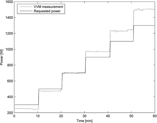
The measured total forward power of all 12 channels combined is shown in together with the nominal BSD power setting, which was increased from 300 W to 1300 W in 200 W steps, with a 10 min measurement interval at each power level. A phase target setting of (0, 0) and an operating frequency of 100 MHz was used for the BSD system. The outputs of the Dodek amplifier were connected to the Sigma Eye applicator, in which a saline-filled phantom was placed.
Figure 2. Nominal (requested) total power and VVM measured total power, i.e. for all 12 channels combined. Dodek amplifier was operated at 100 MHz and connected to the Sigma Eye applicator, which was loaded with a saline-filled phantom.
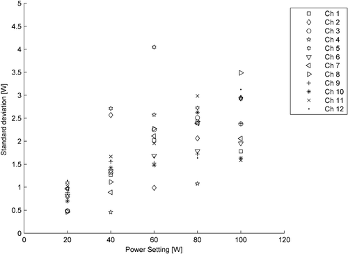
Next, power and phase measurements were performed for each of 12 channels of the Dodek amplifier, using the single-channel mode of the VVM system and with the channel under test terminated in a high-power dummy load. The phase target setting was kept at (0, 0), while the power setting of the active channel was increased from 20 W to 100 W in 20 W increments and kept at each step for 5 min. In order to quantify the performance of the BSD Dodek power control, the average and the standard deviation were computed for the measured power values at each nominal power level, for all the single-channel measurements. shows the relative differences between the averaged VVM system measurements and the nominal power settings of the BSD system. The standard deviation of the measurements, for each channel and at each nominal power level, are shown in .
Figure 3. Relative difference between the average measured power and the nominal power level at 100 MHz, plotted against the nominal power level.
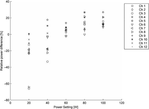
Figure 4. Standard deviation of the measured power at each nominal power level at 100 MHz, plotted against the nominal power level.
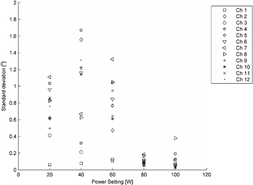
Similarly, to evaluate the phase control performance for varying power levels, the average and the standard deviation were computed for the measured phase values at each nominal power level, for all the single-channel measurements. The average phase values and the corresponding standard deviations, plotted against the nominal power setting, are shown in and , respectively.
Figure 5. Average phase values at each nominal power level at 100 MHz, plotted against the nominal power level.
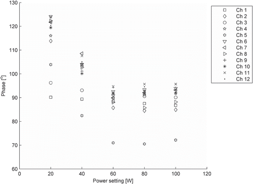
Figure 6. Standard deviation of the measured phase at each nominal power level at 100 MHz, plotted against the nominal power level.
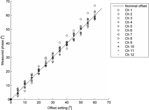
Finally, a simple test of the accuracy of the phase control system of the BSD Dodek amplifier was performed, by using the BSD treatment software phase offset option to add various amounts of phase lag for the output signal, while keeping the nominal power level constant. shows the measured phase values for all channels, plotted against the nominal offset setting, as the latter was increased from 0–60° in 5° increments.
Discussion
VVM system measurement uncertainty
The observed frequency dependence of the power attenuation of the signal paths from the Dodek output, via the directional couplers, cabling and multiplexers, to the VVM input is consistent with the frequency response of the directional couplers Citation[9]. As mentioned above, the extra level of switches and cabling used for channels 1–8 compared to channels 9–12 is a major contribution to the differences between channels; also, there may be differences in the insertion loss of the multiplexer switches themselves. Finally, differences in coupler properties may also contribute to the differences between channels; the coupler manufacturer quotes a 0.3 dB absolute calibration accuracy at 145 MHz Citation[9]. The significant variation of attenuation and phase shift with frequency emphasizes the need for performing attenuation and phase calibration for the entire intended operating frequency range of the VVM system.
The uncertainties related to the power attenuation calibration measurements of the forward and reflected signal paths and the uncertainties of the phase shift calibration measurements do not exhibit any significant variation with frequency. Since the standard deviations (and averages) are computed from seven measurement series only, this means that the relative uncertainty of the standard deviation itself is ∼30%. Hence, it is difficult to conclude whether the observed differences in attenuation and phase measurement standard deviations between channels are statistically significant.
As for the possible contributions to the standard deviations of the attenuation and phase measurements, these include the uncertainty of the network analyser and the calibration procedure associated with its use, as well as the stability of the cabling and connectors. Since the VVM system (and the Dodek amplifier) operates in an essentially temperature-controlled environment at our site, it is not expected that thermal effects contribute significantly to the observed uncertainties. One may speculate that the properties of the electromechanical switches of the multiplexer array could change as the number of operating cycles approaches the ‘lifetime’ of the switches. However, it is not expected that this is the case for the current study, which has been performed over a limited period of time.
Looking at the overall performance of the VVM system, it is seen from that the total power measurement uncertainty—including the measurement uncertainty of the VVM—is less than 4% for all channels for the forward signal and less than 3% for the reflected signal. The uncertainty of the estimate of the total forward power of all 12 channels combined is found to be 0.7%. Further, it is seen from that the total phase measurement uncertainty—including the contribution from the VVM measurement uncertainty—is less than 0.3° for all channels.
Considering that the ESHO quality assurance guidelines for regional hyperthermia Citation[2] recommend that RF-based hyperthermia heating equipment should have a power accuracy of 10% and a phase accuracy of 10°, it is seen that the performance requirements for an independent monitoring system are easily met by the VVM system presented. For the case of phase accuracy, it is also instructive to note that a change of 1 cm in the phase target setting in the BSD treatment software corresponds to a 20° change in phase at the 100 MHz operational frequency of the Sigma Eye applicator (based on a simplified model of energy deposition) Citation[10], Citation[11].
BSD Dodek amplifier measurements
shows that, at 100 MHz, the measured forward power of all 12 channels combined is lower than the requested nominal total power when the latter is below 700 W (nearly −15% deviation at a nominal setting of 300 W) and higher than requested when the nominal value is above this level (close to 20% at a nominal setting of 1300 W). When the requested power value is in the middle of the operating range, however, measured forward power is close to the nominal value. This behaviour is believed to be caused by the PDOS-based version of the Dodek power calibration procedure, during which calibration over the full power range is performed at 75 MHz only, whereas at 100 MHz (and other frequencies), a simple single-point calibration at 50 W per channel is used, corresponding to a level of 600 W total power for all 12 channels combined.
This power-dependent discrepancy between requested and actual power is also confirmed by the single-channel measurements presented in as relative differences between averaged VVM system measurements and nominal requested power levels. While this situation may not pose significant problems during treatments where a uniform power level is used for all Dodek channels, it may potentially influence the applicator energy deposition pattern if non-uniform power settings are employed. Hence, the observed differences between requested and actual power levels emphasize the need for external power measurements.
also shows that, for channels 3 and 8, the power reported by the VVM system is more than 60% lower than the requested level, when the latter is 20 W per channel, and a similar but less pronounced effect is observed when the nominal power level is 40 W per channel. After independent measurements using a Hewlett-Packard HP 436A power meter and an HP 8482A power sensor failed to reproduce these results, the output signals of Dodek channels 3 and 8 were checked with an HP 4395A spectrum analyser, revealing significantly lower output at 100 MHz compared to other channels at nominal power levels below 50 W per channel, but with the ‘missing power’ appearing as sidelobes to the main 100 MHz peak. Thus, the apparent contradictions between the VVM system and the HP power meter results are explained by the fact that the former measures power at the (100 MHz) reference signal frequency only, whereas the latter is a broadband measurement device. The cause of the spectral anomalies for channels 3 and 8 has later been attributed to problems with the PLL circuits for these channels of our Dodek amplifier—there is no evidence to indicate that other Dodek units should be similarly affected. Again, the results illustrate the usefulness of an external power measurement system, but also that some caution is needed when interpreting its results.
As for the standard deviation of the (single-channel) measured forward power at each nominal power level, presented in , it is seen that the values range from 1.5–3.5% at 100 W; this is similar to the range of measurement uncertainty values in , indicating that the Dodek power control is stable, within the measurement accuracy of the VVM system. At low power, however, the observed standard deviation is larger than the estimated measurement uncertainty, thus indicating some contribution from Dodek power control fluctuations.
Turning to the averaged (single-channel) phase measurements at each nominal power level shown in , it is seen that at a given nominal power level, the average absolute phase values for most channels are grouped together within a ±5° interval, with the exception of channel 5, whose value is nearly 20° lower at all power levels, and channels 1 and 3, which are 10–15° lower at 40 W and 25–30° lower at 20 W. The reason for the behaviour of these three channels is not known; considering the spectral anomalies discussed above, it may be speculated that the phase issues of channels 1, 3 and 5 are also specific to the particular Dodek unit. More importantly, it is seen that, although phase values are (mostly) closely grouped for a given power level, the absolute phase values change significantly as the nominal power is reduced below 60 W per channel. Thus, phase steering accuracy may be influenced if significantly non-uniform power settings are employed.
Considering the phase stability at various nominal power levels, it is seen from that at 80 W and 100 W per channel, the observed standard deviation values of the single-channel phase measurements are comparable to the uncertainty estimates from , thus indicating excellent phase stability. At lower power levels (60 W per channel and below), the observed standard deviation values are significantly higher than the estimated measurement uncertainty, but are still satisfactory, being less than 1.7° in all cases.
shows that at a given (constant) power level, the Dodek amplifier is capable of controlling the relative phase values to within ±5° (∼±3° if the slightly atypical channel 3 is excluded), as the nominal phase values are changed from 0–60° in 5° steps.
To summarize, the VVM power and phase measurements of the Dodek output signals show that there are power-dependent differences between actual and requested power. Furthermore, the absolute phase values change significantly when power is reduced below 60 W per channel, but are mostly confined to a small interval at a given, uniform power level. The Dodek power and phase control is stable to within the VVM system measurement uncertainty at the higher power levels and is also adequate at lower power levels. The main significance of these results, however, is that one should exercise caution when employing non-uniform power levels for the different Dodek channels during operation, due to the observed power-dependency of actual phase and power.
Conclusions
The performance of the presented VVM-based system for external monitoring of the output signals from the BSD Dodek amplifier has been evaluated by means of network analyser measurements and subsequent uncertainty analysis. From these measurements, which were performed repeatedly during a period of 2 months, it is concluded that the system possesses the adequate stability and accuracy required for monitoring the steering parameters of the BSD Dodek amplifier. However, it is also desirable to confirm the long-term stability of the VVM system through further, periodic network analyser measurements.
Using the VVM system to investigate the accuracy of the BSD Dodek amplifier power and phase control, it has been shown that there are systematic differences between the nominal requested power and the actual output power of the amplifier and that there are power-dependent variations of the absolute phase of the output signals. These results demonstrate that adding an external power and phase monitoring system to a phased array hyperthermia facility may contribute to improved treatment quality and patient safety. Thus, its use is strongly recommended, especially when attempting to perform treatment-planned, three-dimensional energy deposition steering. In this case, however, characterizing the signal paths from the amplifier outputs to the feeding points of the antennae would be required.
Finally, it is envisaged that universal use of external power and phase monitoring systems could help ensure uniform performance of phased array treatment systems at different institutions, thus contributing to the overall quality of multi-centre hyperthermia studies.
Acknowledgements
The work presented in this paper has been supported by The Norwegian Cancer Society. The authors also wish to thank Mr Hans Olav Rolfsnes (MSc) for performing power meter and spectrum analyser measurements during the investigation of spectral anomalies occurring for two channels of our BSD Dodek amplifier.
References
- Hornsleth SN, Frydendal L, Mella O, Dahl O, Raskmark P. Quality assurance for radiofrequency regional hyperthermia. Int J Hyperthermia 1997; 13: 169–185
- Lagendijk JJW, van Rhoon GC, Hornsleth SN, Wust P, de Leeuw ACC, Schneider CJ, van Dijk JDP, van der Zee J, van Heek-Romanowski R, Rahman SA, Gromoll C. ESHO quality assurance guidelines for regional hyperthermia. Int J Hyperthermia 1998; 14: 125–133
- Gromoll C, Lamprecht U, Hehr T, Buchgeister M, Bamberg M. An on-line phase measurement system for quality assurance of the BSD 2000. Part I: Technical description of the measurement system. Int J Hyperthermia 2000; 16: 355–363
- Lamprecht U, Gromoll C, Hehr T, Buchgeister M, Bamberg M. An on-line phase measurement system for quality assurance of the BSD 2000. Part II: results of the phase measurement system. Int J Hyperthermia 2000; 16: 365–373
- Lee WM, Ameziane A, van den Biggelaar AMC, Rietveld PJM, van Rhoon GC. Stability and accuracy of power and phase measurements of a VVM system designed for online quality control of the BSD-2000 (-3D) DHT system. Int J Hyperthermia 2003; 19: 74–88
- Hewlett Packard. HP 85082A 50 Ω Input operating and service manual insert. Hewlett-Packard Limited;, Queensferry, Scotland 1997
- Expression of the uncertainty of measurement in calibration. European co-operation for Accreditation 1999; 2006, EA-4/02. Available online at: http://www.european-accreditation.org/n1/doc/EA-4-02.pdf, accessed 31 August
- Bentley JP. Principles of measurement systems. 3rd. Prentice Hall, Harlow 1995, Chapter 3
- High Power Dual Directional Coaxial Coupler EME 7020/30A(B) technical specifications, . EME HF-Technik 2004. Available online at: http://www.eme-hf-technik.de/hp-coaxialcoupler.htm, accessed 7 September 2006
- Sigma Eye Applicator Operator Manual (Rev. B). BSD Medical Corporation, Salt Lake City, UT 1995
- Sigma 60 Applicator Operator Manual (Rev. A). BSD Medical Corporation, Salt Lake City, UT 1991
