Abstract
Purpose: To demonstrate the efficacy and predictability of a new conductive interstitial thermal therapy (CITT) device to ablate surgical margins.
Method: The temperature distributions during thermal ablation of CITT were calculated with finite element modelling in a geometrical representation of perfused tissue. The depth of ablation was derived using the Arrhenius and the Sapareto and Dewey (S&D) models for the temperature range of 90 to 150°C. The female pig animal model was used to test the validity of the mathematical model. Breast tissues were ablated to temperatures in the range of 79–170°C, in vivo. Triphenyltetrazolium chloride viability stain was used to delineate viable tissue from ablated regions and the ablation depths were measured using digital imaging.
Results: The calculations suggest that the CITT can be used to ablate perfused tissues to a 10–15 mm width within 20 minutes. The measured and calculated depths of ablation were statistically equivalent (99% confidence intervals) within ± 1mm at 170°C. At lower temperatures the equivalence between the model and the observations was within ± 2 mm.
Conclusion: The CITT device can reliably and uniformly ablate a 10–15 mm wide region of soft tissue. Thus, it can be used to secure negative margins following the resection of a primary tumor, which could impede local recurrences in the treatment of local diseases such as early staged, non-metastatic, breast cancer.
Introduction
Thermal ablation of soft tissues is gaining acceptance as a technique to irreversibly damage tumours and margins with high temperatures Citation[1]. While early works focused on tumour ablation, it has been suggested that thermal ablation could also be effective in ablating surgical margins to inhibit local recurrence due to the presence of microscopic cancer cells left behind after the primary tumour resection Citation[2].
The standard of care in the treatment of solid cancerous tumours is primary tumour resection. However, it is practically impossible to assure that there are no microscopic viable cancer cells residue left at the site of the resection, which could lead to reemergence of the disease Citation[2–4]. This problem is encountered routinely in the treatment of non-metastatic solid tumours in the head and neck and breast Citation[4–6]. In breast cancer, following the initial lumpectomy, recurrence rates of 20–56% have been reported Citation[3], Citation[4], Citation[7], Citation[8]. While some recurrences can be attributed to multiple foci and diffuse tumours, 32% (i.e. about 60% of the local recurrences) result from inadequate surgical margins with viable cancer cells remaining at the lumpectomy site (i.e. positive margins)Citation[3], Citation[4], Citation[9]. To ensure tumour-free margins at the operative site after breast tumour resection, whole-breast external beam radiation and brachytherapy are being used postoperatively Citation[10–14]. In addition, intraoperative thermal ablation can reduce the probability of local recurrence and maintain acceptable cosmesis, as presented in the results of a recent clinical study using radiofrequency ablation (RFA) Citation[2]. In that study, 24 of 41 patients did not have postoperative radiation therapy, and no in-site local recurrences occurred during a median follow-up of 24 months (12–45 months). The ablation was performed with a radiofrequency device whose temperature reached 100°C.
Thermal ablation techniques, such as radiofrequency ablation Citation[15–22], laser ablation Citation[10–14], Citation[23–26], cryotherapy Citation[27], Citation[28], and focused ultrasound with MRI guidance Citation[1], Citation[29–34], have shown promising results by destroying cancer cells via thermal energy delivery to target tissue. A common denominator among all these techniques, excluding cryotherapy, is that electromagnetic or acoustic energy is selectively absorbed by various tissue components and is converted to heat. The generated heat is then dissipated mainly by conduction to induce irreversible thermal damage by coagulation necrosis. Heat dissipation in conductive thermal ablation can be modelled using well-understood heat transfer principles Citation[35–37]. The changes in the heat conduction coefficients of soft tissues during ablation are relatively small from 37°C to over 100°C Citation[38]. In addition, the thermal diffusivity (α) that dictates heat transfer in conduction is very similar for all soft tissues with an average of α = (12.84 + 0.53·T)·10−8 ± 1.56·10−8 m2/sec Citation[38]. Thus, the rate of heat transfer in tissues during conductive ablation may be simulated fairly accurately via mathematical modelling, even if the actual thermal properties of the specific tissue in the model are not known. In this work the thermal properties for porcine breast tissue were assumed to be the same as skin tissue, which is a reasonable approximation for the tissue that is being tested (as detailed in the materials and methods).
The CITT device is made from a power supply and customized metal probe. Heat is delivered to the tissue with an electrically heated ceramic covered metallic sphere placed at the end of the CITT probe that includes deployable pins, which can be retracted for insertion and removal of the CITT probe (US patents 6 780 177 and 6 872 203). The deployable metal pins enhanced heat transfer into the surrounding tissu Citation[39], Citation[40]. The pins differentiate the CITT device from the endometrial balloon ablation device that also induces thermal ablation by conduction Citation[35], Citation[36], Citation[41–43]. The pins increase the effective surface area of the CITT probe. In addition, the rate of heat transfer to the tissue is increased since the thermal diffusivity of the metal pins is one order of magnitude larger than that of soft tissues Citation[44], Citation[45]. Furthermore, the pins also penetrate the carbonized layer that forms during exposure of live tissue to higher than 100°C temperatures Citation[46].
The predictability and control of the CITT device was demonstrated by comparing calculated with observed thermal ablation depths demarcated with viability staining in fresh tissue resected from the treated region Citation[47]. CITT ablations were performed in breast tissue of live female pigs (swine model), an accepted model for studying interstitial thermal therapy for thermal ablation because of the similarity of the swine mammary tissue to human breast tissu Citation[48], Citation[49]. The temperature distribution during the thermal ablation process was calculated using a numerical model of the bio-heat equation solved using a finite element method (FEM) commercial package (Femlab, Comsol Inc., Burlington, MA) Citation[35], Citation[50–52]. The mathematical modelling included the effect of local cooling, via blood flow in blood vessels, on the temperature's distribution. The onset of thermal damage was derived using the Arrhenius Citation[10], Citation[35–37, 33] and Sapareto and Dewey (S&D) thermal-dose models Citation[54–57]. These are well-established models to calculate the coagulated zone or comparison with histologically observed thermal damaged zones Citation[35], Citation[36], Citation[52], Citation[57], Citation[58]. The depth of the ablated region was calculated from digital images of tissue sections (taken from the ablated region) using customized Matlab™ (Mathworks, Natick, MA) script for image analysis. The confidence-interval equivalent of the Two One-Sided Tests (TOST) procedure of Schuirmann (1987) Citation[59] was employed to demonstrate statistical equivalence between observed and calculated ablation depths.
Materials and methods
The prototype device was designed using computer aided design software (ProEnginneer™) (). The device consists of an interchangeable arm that is mounted on a small reservoir (). At the end of the arm there is a 20-mm-diameter sphere () including deployable pins (3 mm long and 1 mm diameter) that can be extended perpendicularly to the surface of the sphere (). The heat is generated at the centre of the sphere via joule heating with a miniature heating coil element under computer control. The heating rate is proportional to the current passing through the coil, and the temperature, and thus the current, is controlled with a proportional-integral-derivative (PID) controller that is connected to a thermocouple that reads the temperature at the centre of the heated sphere.
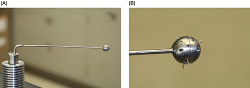
Figure 1. CITT handle and probe (A) and close up (B) of the end of the spherical tip showing the deployable tips that can be retracted for insertion and removal. (published with permission from: Conductive Interstitial Thermal Therapy (CITT) Device Evaluation in VX2 Rabbit Model, Technology in Cancer Research and Treatment, 6(3), 235–46, 2007. Adenine Press, http://www.tcrt.org)
Mathematical modelling
The purpose of the model is to investigate the thermal ablation process by calculating the temperature distribution and the size of the ablation zone as a function of time and temperature (thermal dose), during ablation. The temperature distribution is calculated by solving the long-established equation for heat transfer by conduction and convection in perfused tissues (also so called the bioheat equation of Pennes) Citation[60–62] given by:
T is the temperature as a function of time (t); k is the thermal conductivity (W/m/°C); ρ is the density (kg/m3); Q represents internal heat sources (W/m3) and is set to zero because metabolic contributions are ignored in modelling conductive heatiCitation[35], Citation[36], Citation[58]; and υ(T) is the perfusion rate (mb3/m3/sec; cubic metre of blood mb in cubic metre of perfused tissue ‘m’) as function of temperature, Citation[35], Citation[52]. It is assumed that the perfusion will cease when the temperature exceeds critical value (60°C) Citation[63]. C(T) is the specific heat capacity (J/kg/°C) as a function of temperature (T) and includes the latent heat L (J/kg) for evaporation of the relative water content, in the tissue, at T = 100°C, as shown in equation 1a. In this analysis we assumed that the liquid-to-gas transition occurs over 1°C, ΔT = 1°C.
Following the phase transition, the specific heat returns to its original value. This method has been used previously in modelling laser heating of tissue, was validated in animal models, and agreed with clinical dCitation[51], Citation[52], Citation[64]. Solving equation 1 provides the temperature as a function of space and time, T(x, y, z, t). As we recently showed in modelling thermal heating by laser Citation[51], Citation[52], Citation[64], Citation[65], equation 1 can be solved numerically for heterogeneous tissue, with blood perfusion and surface cooling included, using Femlab™ (Comsol Inc., Burlington, MA). For initial conditions, the core tissue temperature (at time t = 0) was assumed to be 37°C, and tissue external surface temperature was set at 26°C. Heating is simulated by changing the boundary condition (T(t)) at the outer boundary of the heating element coil (shown in ) at the point we measure and control the temperature.
Figure 2. The geometry of the model showing a cross section of the CITT probe inserted into a tissue cavity. The red ellipses represent blood vessels randomly distributed within the tissue (A), and the progressive mesh of 11038 elements used in the FEM (B). (published with permission from: Conductive Interstitial Thermal Therapy (CITT) Device Evaluation in VX2 Rabbit Model, Technology in Cancer Research and Treatment, 6(3), 235–46, 2007. Adenine Press, http://www.tcrt.org)
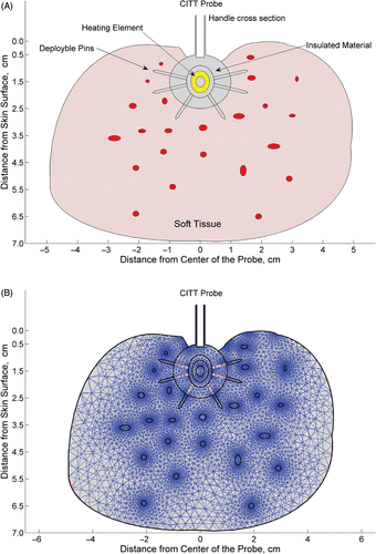
The right side of equation 1 includes heat transfer via blood flow, where Tart is the arterial blood temperature, 37°C. The boundary condition on external tissue surfaces exposed to natural convection by air is given by equation 2:where Tamb = 26°C (the ambient temperature). The thermophysical parameters of the breast fat tissue were taken from Robinson et al. Citation[66], in which the thermal conductivity was 0.246 W/m/°C, the specific density was 934 kg/m3, the specific heat capacity was 2.22 kJ/kg/°C, and it was assumed that the adipose tissue specific heat capacity was about 80% of water. To study the effect of perfusion on the temperature field, the perfusion rate was varied from zero to a maximum of 0.017 mb3/m3/sec (i.e. 18.73 kg/m3/sec). This value represents tissue cooling by blood perfusion in the microvasculature in an organ such as porcine liver Citation[53]. As the porcine breast tissue is not as highly vascularized as liver, we used it in constrained regions representing thermally significant blood vessels (0.2–4 mm diameter) randomly scattered throughout the tissue (see ).
The geometrical model that was used to calculate the temperature distribution within a 10-cm-by-7-cm tissue structure is shown in . This configuration represents a 2-dimensional (2D) cross-sectional plane along the centre of the CITT probe inserted in a tissue cavity of 2 cm in diameter. A 2D model was selected due to the spherical symmetry of the CITT probe and the need to compare the calculation results to histological observation that can only be done in 2D. The entire geometry was meshed using a progressive mesh generated by Femlab (). It is assumed that the tissue conforms to the probe surface. This assumption is based on the fact that once the tissue begins to coagulate, it will shrink as it loses water due to heating, and is therefore likely to tightly encompass the CITT probe. We bear in mind that the tissue may not tightly fit the probe in all cases, but our experimental data support this assumption thus far. Furthermore, surgeons can employ various techniques to keep the tissue in contact with the CITT in real time Citation[2].
Thermal damage
To predict the extent of thermal damage within the tissue, we use and compare the Arrhenius model (rate process integral) Citation[10], Citation[35–37], Citation[53] and the S&D thermal-dose model as detailed below Citation[54–57].
Arrhenius model
Given the temperature distribution, T(x, y, t), as a function of time and space, the perimeter of the coagulated zone can be calculated using the Arrhenius model by the rate process integral in equation 3:where Ω(x, y, t) is the thermal damage parameter; C0 is the concentration of undamaged cells at time 0; Ct is the concentration of undamaged cells at time t; A is the frequency factor (1/sec) or the molecule collision rate; Ea is the activation energy for molecular denaturation (J/mole); and R is the universal gas constant of 8.3144 J/mole/K. Since there is no published data for the frequency factor and the activation energy of breast tissue, and there are quite a few studies on burns injury in skin, Citation[37], Citation[67–71] a tissue that is similar to breast tissue in the porcine model, in our calculations we used the following skin tissue values: Ea = 602820 J/mole and A = 8.73 × 1094 1/sec. Citation[71]. Assuming that there are no damaged cells at t = 0 (C0 = 1) and substituting Ct with the concentration of damaged cells Cd = 1−Ct; a simple rearrangement of equation 3 yields:
Per the Arrhenius model, we define a complete coagulation as occurring when Ct → 0 or Cd = 1.
S&D thermal-dose model
This model was developed by Sapareto & Dewey Citation[54] to determine the thermal dose required for a successful hyperthermic treatment at a given time and temperature with reference to another baseline temperature. When examining many biological systems, Sapareto & Dewey Citation[54] found that there is an exponential relationship between temperature and exposure time for most in vitro and in vivo systems so that:where t1 and t2 are the equivalent times for T1 and T2 respectively, and Rc is an empirically derived constant. Furthermore, they also found that with reference to 43°C, one degree of increase in temperature requires a two-fold decrease in time for the same effect above 43°C and a three- to four-fold increase in time for an isoeffect below 43°C Citation[54]. Thus, there is a ‘break’ point around 43°C, where Rc = 0.25 below 43°C and Rc = 0.5 above 43°C. For any given temperature the r thermal dose can be calculated with reference to 43°C using equation 6
where t43 is the equivalent time at 43°C, T is the average temperature during time Δt. This model has been tested in many clinical studies and is well-accepted to determine thermal doses in hyperthermia Citation[55–57]. In this model, the threshold thermal dose for complete cellular destruction (coagulation necrosis) is the equivalent time of 240 minutes at 43°C Citation[56], Citation[57]. Thus, wherever the equivalent time t43 > 240, we will assume that cells in the region have been killed. To predict the perimeter of the damage zone in CITT, we calculate t43 (using equation 6) for the S&D model and Cd (using equation 4) for the Arrhenius model at each ‘x, y’ point in the geometry (shown in ).
In vivo ablation in a swine model
Approval for the animal experiments was obtained from the University of Arkansas for Medical Sciences (UAMS) Institutional Animal Care and Use Committee (IACUC), prior to initiation of the study. The female pig model was selected because it is an accepted model for studying interstitial thermal therapy for thermal ablation in human-like breast tissu Citation[48], Citation[49]. An adult, non pregnant, 525-lb swine was purchased, acclimated for a few days, and prepared for the ablation study. The animal was pre-anesthetized and intubated for general anesthesia using Isoflurane (4.5%) with 3–4 l/min oxygen flow. The animal was laid on its back and the breast was cleaned and disinfected using betadine and prepared for CITT ablation (Fgure 3A). Prior to ablation, a 3–4-cm incision was made under the nipple. A cavity of approximately 3 cm in width was created at about 1.5 cm under the skin surface. The probe was inserted into the cavity (). Ablations were performed on tissue under eight nipples for temperature range of 79° C to 170°C and total ablation times of 17 to 25 minutes, as detailed in . The sequence of ablation (detailed in ) was chosen so that adjacent nipples were ablated at least 40 minutes apart.
Figure 3. Swine, 525 lbs, prepared for CITT ablation. The nipples were numbered 1–15, to indicate the site of ablation at each point of time (A). The CITT probe is positioned inside the simulated lumpectomy cavity (B).
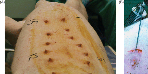
Table I. Probe maximum temperature and ablation time, at maximum temperature, used in the in vivo study where ablation was performed in the breast tissue, under the nipple, of an adult swine. The right column indicates the site/location of where the ablation was performed (see ) and the order (sequence).
Following each ablation the cavity was cleaned and closed with a nylon suture (Ethilon 2–0, Ethicon, Cincinnati, Ohio). Twenty-four hours post-ablation, the ablated sites and 1–2 cm of adjacent tissue were removed and placed in saline at 2–4°C (before euthanasia). Immediately thereafter, the specimens were transferred to the lab for histological processing. First, the entire excised tissue was embedded in HistOmer™ (Vibratome Company, St. Louis, MO), a room-temperature embedding polymer designed to orientate all organs and soft tissues for mechanical slicing Citation[72]. The HistOmer is an alginate cold polymer, and when mixed with water or saline (1:1 volume ratio), it polymerizes at 26°C within 60 seconds and holds the tissue in place without affecting fresh tissue properties. Five minutes after embedding in the HistOmer, the fresh tissue blocks were sliced (4 mm thick). The 4-mm slices were stained for viability with 1% triphenyltetrazolium chloride (TTC) solution (in phosphate-buffered saline) for 1 hour at 37°C. In viable tissue, TTC is reduced intracellularly by the mitochondrial enzyme succinate dehydrogenase to formazan, a water-insoluble red compound that remains inside the cell. This reaction does not occur in non-viable tissue Citation[47], which remains unstained (white to tan). Following TTC staining, the tissue was removed from the solution, and sections were photographed with an 8-megapixels digital camera (Canon EOS Rebel 350D/Digital Rebel XT, Canon NY, NY) and Canon Macro lens–100 mm–f/2.8 (Canon, NY, NY).
The ablated region was calculated from each picture using in-house developed algorithm implemented as a Matlab™ (Mathworks, Natick, MA) script. In the first step, the algorithm segmented images into viable tissue, ablated tissue, and the image background. Since the viable tissue identified by TTC staining is characterized by appearance in shades of red, and the colour of background is known, the segmentation was based on threshold evaluation of hue in 3-by-3-pixel sliding sections in the hue-saturation-value (HSV) representation of the image. The hue evaluation criterion was further complemented with geometrical growth of detected ablated region starting at the CITT probe centre and expanding in radial directions (as expected for heat dissipation) to increase the robustness of the algorithm. In the second step, radial distances between the inner contour (probe surface) and the outer contour of ablated region are measured around the CITT probe centre in 1 degree angular increments. The distance between the inner and outer contours was identified as ablated margin width. Finally, minimum, maximum, and mean values with standard deviations of measured margins were calculated.
Statistical analysis
Calculated and observed ablation distances were evaluated for statistical equivalence using the confidence-interval equivalent of the Two One-Sided Tests (TOST) procedure of Schuirmann (1987) Citation[59]. Briefly, two parameters q1 and q2 are considered equivalent if their difference lies within a tolerance window centred on zero and defined by user-specified “equivalence limits” of ±d. The TOST procedure consists of two one-sided statistical hypothesis tests of the difference in parameters, first of H0: q1–q2 ≥ + d vs. HA:q1–q2 < + d, then of H0: q1–q2 ≥ –d vs. HA:q1–q2 > –d. If both of the one-sided tests are conducted at a 5% significance level (a 5% alpha), then the entire TOST procedure is a 5% (and not a 10%) alpha-level test procedure Citation[73]. In terms of confidence limits, this means that q1 and q2 are considered equivalent at 5% alpha if the 90% (and not the 95%) confidence interval around q1–q2 lies entirely inside the equivalence limits of ±d. For this experiment, a model was considered equivalent to the histology for a particular temperature if the average difference between the two at that temperature was within ±1 mm. Each model was compared to histology via the above TOST confidence-interval method at the eight probe temperatures, using 99% confidence intervals (i.e., 0.5% alphas) to adjust for the multiple comparisons. Because of underlying non-normality of ablation distances for histology and models alike, the 99% confidence limits on the mean difference in distances were chosen to be the 0.005 and 0.995 quantiles of the resampling distribution obtained from 10,000 Bootstrap resamplings of the data.
Results
Mathematical modelling
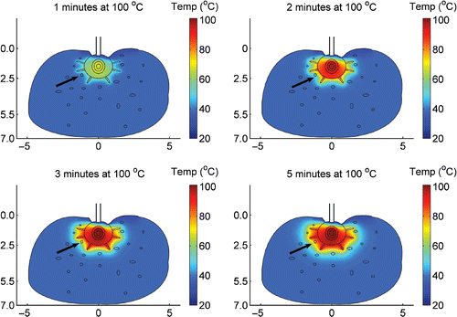
The temperature distribution within the tissue ablated by CITT was calculated for 10, 15, 20 and 25 minutes of ablation time at maximum probe temperatures of 90, 100, 110, 120, 130 and 150°C. In we present a representative colour coded plot that shows the temperature distribution for maximum probe temperature of 100°C after 20 minutes of ablation. The maximum temperature is at the centre of the CITT probe, at the heating element. Heat dissipates via conduction from the centre towards the surface of the probe and pins that are in contact with the tissue. It takes 2 minutes for the probe and pins to reach maximum temperature (). Within 4 minutes (), the temperature of the tissue in close proximity to the spherical probe (<3mm rind) exceeds 60°C, and significant coagulation commences. The cooling effect due to blood perfusion manifests itself through deformation of the isotherms in the vicinity of a large blood vessel (arrow) on the left side of the CITT (). During the first 4 minutes, blood perfusion in this vessel reduces the tissue temperature as compared to the temperature of the contralateral side of the CITT (), where it takes one more minute () for that particular blood vessel to coagulate. At the end of the ablation (at time of 20 minutes) a fairly uniform temperature distribution is predicted ().
Figure 4. Calculated temperature field within tissue unit volume following 12 minutes ablation by CITT at maximum temperature of 100°C at the CITT tip. Includes high blood flow and assumes that the tip conforms to the tissue.
The calculated perimeters of thermally ablated tissue for maximum probe temperatures of 90, 100, 110, 120, 130 and 150°C are shown in . For the Arrhenius model the perimeters are iso-damage lines of where Cd = 1 and for the S&D model these lines are located where the equivalent time t43 = 240 min. Thus, it is assumed that the tissue region between these iso-damage contours and the probe surface underwent coagulation necrosis (i.e. ablated region). For ablation time of 10 minutes () the ablated region increases with maximum temperature. Increasing ablation time to 15 minutes () slightly narrows the differences between the iso-damage contours calculated for temperatures above 100°C. When the total ablation time is 20 and 25 minutes, the ablated region for temperature above 100°C is almost identical (). The Arrhenius and the S&D thermal dose model predicted similar ablated zones for temperatures above 100°C, as illustrated in .
Figure 5. Calculated perimeters of the ablated zones due to CITT ablation at maximum probe temperature range of 90 to150°C for 10, 15, 20 and 25 minutes ablation. The Arrhenius model was used in ; the S&D model was used in .
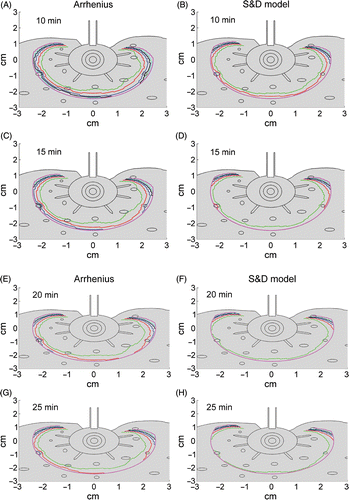
Figure 6. The predicted thermal zone for the Arrhenius model (AR–green line) is compared to the ablated zone calculated with the S&D model (S&D–red line). Note at maximum probe temperature of 100°C the S&D model predicts slightly larger zone of ablation than the AR (A,B); and at maximum probe temperature of 150°C both models predict same size zone of ablation (C,D). In Figure D, the dashed lines show the ablation margin calculated in where the distances from the contours to the CITT face were calculated for all the points on the green and red lines from E to W.
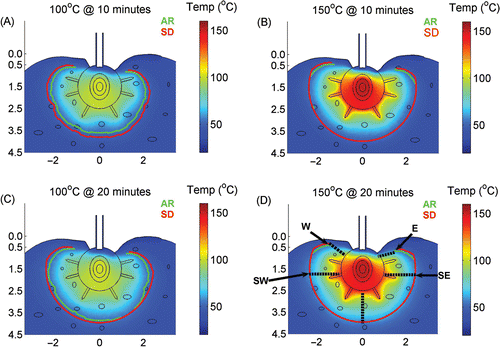
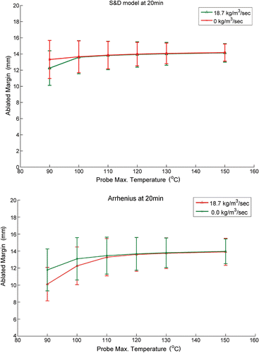
The width of the ablated margin was defined as the distance between the perimeter of the ablated zone and the surface of the CITT sphere, dotted lines in . These distances were calculated along the perimeter of the ablated region every 1 mm, and the mean value (of ablated margin) was plotted as a function of temperature and blood perfusion for both thermal damage models (Fgure 7A, B). This analysis suggests that blood perfusion has a minor effect on the width of the ablated margin. Notably, to minimize skin damage near the tissue surface (e.g. points W and E in ) the ablated region in the vicinity of these points is intentionally narrower in comparison to regions between points SE and SW in . Hence, the standard deviation in the ablated margin width in is attributed to this intended variation of the ablated margin width.
Figure 7. The ablated margin width calculated from the data presented in and .
In vivo ablation
The resulting ablation zone within the cavity is shown in . It is noteworthy that while the tissue inside the cavity appears to be carbonized adjacent tissue and superficial skin appear undamaged. TTC staining of an ablated section is shown in . The ablated region (white/brown tint) is confined by a line contour to delineate the viable (red) from non-viable regions (white/brown) stained by TTC (). The arrow in this figure identifies an ablated blood vessel (4 mm in diameter) within the ablated region. The ablated margin was defined as the distance between the surface of the cavity, that was in contact with the CITT probe (shown as a circle in ) and the line along the perimeter of the ablated zone (). The calculated and observed ablated margins widths were plotted as function of the probe maximum temperature ().
Figure 8. A close up of the cavity shown in after CITT ablation was completed. The cavity inside wall (margins) appears carbonized, but adjacent tissue and superficial skin are undamaged.
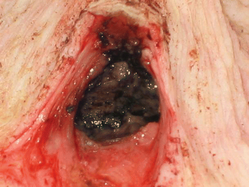
Figure 9. TTC staining of a section taken from the centre of the ablated cavity shown in . The black line is the calculated contour of the ablated zone.
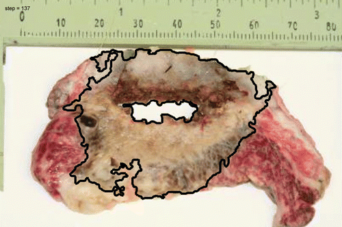
Figure 10. Calculated and observed ablated margin width as function of CITT probe maximum temperature.
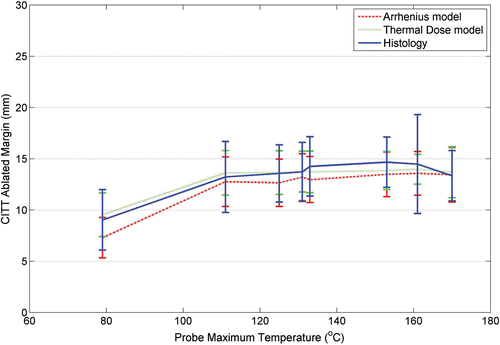
The calculated data appears to agree very well with the histological observations. The equivalence of observed to calculated ablation depths was further investigated via statistical analysis. reports the results of testing for equivalence between models and histology via the TOST confidence-interval method. At 170°C, the 99% confidence intervals for both models lay entirely within ±1mm, demonstrating equivalence with observation at this high temperature. However, at 133°C, 151°C, and 161°C, the upper 99% confidence limits for both models exceeded the upper equivalence limit at +1mm, showing that none of the models produced results equivalent to observation at these temperatures. Nonetheless, at these temperatures, the thermal dose models produced upper confidence limits below +1.5mm, whereas the Arrhenius model with blood perfusion produced upper confidence limits between +1.5mm and +2.0mm, and the Arrhenius model (assuming no blood flow) produced upper confidence limits in excess of +2.0mm. At 79°C, only the S&D model without blood perfusion had its 99% confidence interval entirely inside ±1mm. By contrast, at 79°C, the Arrhenius model had their lower as well as their upper 99% confidence limits lying above the upper equivalence limit at +1mm, suggesting a bias towards underprediction for the Arrhenius model at this temperature. At 111°C, 125°C, and 131°C, the 99% confidence intervals lay entirely within ±1mm for S&D model.
Table II. Equivalence-testing results for model calculations versus observed histology.
Discussion
Conductive interstitial thermal therapy (CITT) device
Thermal ablation of tumours and margins is gaining acceptance as complementary treatment in the management of solid tumours Citation[2], Citation[22], Citation[23], Citation[25], Citation[26], Citation[74–79]. Herein we present a patented device, conductive interstitial thermal therapy device (CITT), for soft tissue ablatio Citation[39], Citation[40]. The concept of conductive ablation is used clinically in endometrial ablation with thermal balloons to treat menorrhagia or dysfunctional uterine bleeding Citation[35], Citation[41–43]. In thermal balloon endometrial ablation, a latex- or silicone-based polymer balloon is inserted into the uterus and filled with a fluid, such as saline or sterile 5% dextrose in wCitation[35], Citation[43], Citation[74]. Under constant pressure of 80–200 mm Hg, the fluid is heated to 75–92°C through heating elements inside the balloon for 7–12 min. Thermal balloon endometrial ablation is considered safe and effective, in comparison to endometrial ablation using laser or radiofrequency Citation[42], Citation[74–76]. The CITT device is based on the same physical principles as balloon ablation. However, in order to effectively ablate surgical margins, the CITT probe is made from biocompatible metal, the probe maximum temperature can exceed 100°C, and metal pins are used to improve the heat delivery to the target tissue. Increasing the probe temperature above 100°C will not immediately increase tissue temperature above 100°C. The additional energy (due to probe temperature increase above 100°C) will first be consumed by the latent heat of water evaporation and thereafter induce tissue carbonizatioCitation[52], Citation[77], Citation[78]. The carbonized layer represents non-viable tissue. The CITT device can deliver heat through the carbonized layer to the adjacent tissues, since this electrically insulated layer can conduct heat (as ceramic material). By comparison, the formation of a carbonized layer is fairly undesirable in thermal ablation using laser techniques and radiofrequency Citation[77], Citation[78]. Tissue carbonization will significantly increase laser absorption, and the excessive laser energy will turn into uncontrolled excess heat, resulting in a ‘run-away effect’, whereby the laser beam, propagating through the carbonized layer at a fast rate, causes the tissue beyond the initial carbonized layer to carbonize as well. Consequently, the laser beam could reach the skin or a vital organ and cause undesirable damage. The carbonized layer is also an electrical insulator Citation[46]. Thus, if formed during RF ablation, it would disrupt the electric current between the electrodes and could interrupt the radiofrequency ablation. The formation of a carbonized layer may inhibit heat propagation to deeper tissues, however, CITT's metal pins enable heat flow from the probe (which contains the maximum energy anywhere) to the lower temperature tissue even through the carbonized layer. The probe itself is coated with an electrically insulating material to improve the heat flow from the probe to the tissue. Electrically insulating materials usually have lower thermal diffusivity, and are thus easier to heat up (Holman JP, Heat transfer) Citation[45] and use as a heat source for conductive thermal ablation.
The effect of blood perfusion
The effect of the blood flow was also found to depend on the probe temperature. A high blood-flow rate decreased the local tissue temperature, as also found by Liu et al. for radiofrequency ablation Citation[79]. However, for CITT probe temperature above 100°C, our model predicts that blood perfusion will have little effect on the size of the ablated zone. At these high probe temperatures and thermal dosages, the amount of energy delivered by the CITT overwhelmed the cooling effect of blood flowing in vessels of 0.2 to 4 mm diameters. The size of the ablation zone does not increase linearly with probe temperature, as some of the heat (energy) is consumed by the latent heat.
Modelling temperature distribution and thermal damage
The CITT control relies on our ability to predict the thermal field during ablation. We can accurately model the transfer of heat from the probe to the tissue, since the changes in heat conduction coefficients in tissue accompanying heat are linear and known Citation[38]. Our modelling results were equivalent to within ±1mm with observed histology at the highest temperature tested (170°C), and usually in good agreement with observed histology (i.e., within ±2mm) at the lower temperatures tested. At all temperatures below 170°C, the S&D model agreed more closely with observed histology than the Arrhenius model, even when equivalence to within ±1mm could not be demonstrated. Whereas the S&D model was derived from empirical data the Arrhenius model is based on classical thermodynamic principles Citation[54], Citation[80]. The S&D model includes the effect of hyperthermia during ablation, the Arrhenius model does not take into account cell's death due to hyperthermia that could occur at the outskirts of the ablated region Citation[1]. However, at high temperature ablation (>100°C) the S&D 240 equivalent minutes at 43°C is comparable to complete cell coagulation (Cd = 1) in the Arrhenius model. There are uncertainties in the values of the activation energy (Ea) and frequency factor (A) used to calculate the ablation depth with the Arrhenius model. Both constants were assumed to be for dermis (in this work), in absence of better data. However, Pearce et al. showed that variations in the derived process frequency factor (A: 3.1 × 1098–8.73 × 1094) and activation energy (Ea: 575–628 KJ/mole) have minor effects on the critical temperature Citation[71]. Thus our choice to use Arrhenius constants for skin to calculate the ablation depth predicted is reasonable. The ablation depths predicted by the two thermal damage models suggest that S&D and Arrhenius models are equally accurate in predicting the thermal damage following CITT. The relatively minor differences in predicted ablation depth and actual ablation death may be explained by the time at which tissues were resected and the effect of progressive injury, which isn't taken into consideration in these mathematical models Citation[81]. It has been demonstrated that peak progressive thermal damage occurs, at least in liver models, at 24–72 hours post-ablatio Citation[82], Citation[83].
Clinical application
The concept of surgical margins is based on the notion that positive margins equate to local recurrence. When surgical resection is performed, all margins are tested intraoperatively by pathologic evaluation. Once the margins are clear the wound is closed at the primary site. Only when the permanent margins are returned five to seven days later are the true margins known. In rare cases would positive margins extend beyond a true 5 mm. This approach has been shown useful in one clinical study conducted at our institution Citation[2]. In that particular study, Klimberg et al. reported the use of radiofrequency ablation to thermally ablate margins following the resection of a primary early staged breast tumour. The radiofrequency ablation was performed at temperatures as high as 100°C. The cosmesis which resulted from the RF ablation was acceptable and no major concerns were raised with respect to tissue healing. Concerns regarding RF ablation technology involve its reproducibility and temperature controlCitation[50], Citation[84], Citation[85]. Because most of the energy is preferentially absorbed by water and fat, tissues with high water or fat content reach much higher temperatures than tissues with low water or fat content. Therefore, if the tissue between the electrodes has higher water or fat content than those near the electrodes, the temperature of the tissue between the electrodes could be significantly higher than the temperature measured by the electrodes. This well-known effect has not been researched extensively due to the lack of information on the temperature dependency of the electrical properties of various tissues Citation[86]. Wren et al. found temperature deviations of 3–12°C during RFA of brain lesions Citation[85]. Chang indicates that significant errors can arise when constant electrical conductivity is assumed; he further states that the errors will not depend on the power, but rather on the temperature at which RFA will operate Citation[50]. Thus, the tissue temperature throughout the treated region must be calculated Citation[50], Citation[85]. This can be done by finite element modelling (FEM) of the radiofrequency–tissue interaction, which has been the subject of several publications Citation[50], Citation[85], Citation[87], Citation[88]. Whereas the mathematical approach and governing equations (Maxwell's and heat transfer) are well known, the main issue is the temperature dependence of the dielectric properties, such as electrical conductivity. These changes affect the heating rate, heat transfer and calculated temperatures, and have not, as yet, been incorporated into the modelling of radiofrequency ablation. Another limitation of the radiofrequency ablation is the inability to reproduce clinical results as indicated in a recent report from MD Anderson and attributed to the fact that the method requires highly specialized skills Citation[84]. Works are being done to improve the reliability and reproducibility of radiofrequency ablation.
However, for margin ablation where the target tissue is within 5–10 mm from the cavity wall the CITT could be the method of choice. CITT is more predicable and controllable than radiofrequency ablation, since the governing thermophysical constants are known and linear, and the maximum temperature is always at the probe surface, and thus, readily controllable Citation[38]. Hence, we posit that the CITT is an effective method to ‘clear’ margins and could extend the tumour-free margin by at least 10 mm thereby reducing the chance of local recurrence.
Clearly, we recognize that in some cases true margins cannot be achieved through ablation. In certain cases the margin may involve a vital structure such as the common or internal carotid artery, in the head and neck; or when positive margins are due to perineural or lymphvascular involvement, chemoradiation is the often the preferred method to reduce the chance of local recurrence.
Conclusion
Using either the Arrhenius or the S&D model the size of the ablated zone can be calculated with 1–2 mm accuracy during CITT ablation. The CITT device can be used to ablate soft tissues up to 10 mm away from the probe surface in presence of thermally significant blood vessels. In that context, CITT appears to be a strong candidate for thermal margin ablation. Ensuring negative margins following resection of primary tumours is a much needed clinical application in treatment of local diseases, such as non metastatic head and neck and breast cancer. Negative margins can prevent local recurrence. The CITT could be used intraoperatively to deliver a prescribed thermal dose to create a rind of ablated tissue around a surgical cavity, effectively and reliably. More work is underway, with a new modified CITT probe, to demonstrate the clinical application of CITT.
Acknowledgement
Funding for this work was provided by the National Cancer Institute NIH/NCI Grant No. 5R21 CA108678-01.
P Novak and EG moros have been supported in part by the Central Arkansas Radiotherapy Institute.
References
- Diederich CJ. Thermal ablation and high-temperature thermal therapy: Overview of technology and clinical implementation. Int J Hyperthermia 2005; 21(8)745–753
- Klimberg VS, et al. eRFA: Excision followed by RFA - A new technique to improve local control in breast cancer. Ann Surg Oncol 2006; 13(11)1422–1433
- Mullenix PS, et al. Secondary operations are frequently required to complete the surgical phase of therapy in the era of breast conservation and sentinel lymph node biopsy. Am J Surg 2004; 187(5)643–646
- Singletary SE. Surgical margins in patients with early-stage breast cancer treated with breast conservation therapy. Am J Surg 2002; 184(5)383–393
- Johnson RE, et al. Quantification of surgical margin shrinkage in the oral cavity. Head Neck 1997; 19(4)281–286
- Spiro RH, et al. Pattern of invasion and margin assessment in patients with oral tongue cancer. Head Neck 1999; 21(5)408–413
- Cellini C, et al. Factors associated with residual breast cancer after re-excision for close or positive margins. Ann Surg Oncol 2004; 11(10)915–920
- Schnitt SJ. Risk factors for local recurrence in patients with invasive breast cancer and negative surgical margins of excision. Where are we and where are we going?. Am J Clin Pathol 2003; 120(4)485–488
- Henry-Tillman R, et al. Intraoperative ultrasound and other techniques to achieve negative margins. Semin Surg Oncol 2001; 20(3)206–213
- Arthur DW, et al. Partial breast brachytherapy after lumpectomy: Low-dose-rate and high-dose-rate experience. Int J Radiat Oncol Biol Phys 2003; 56(3)681–689
- Keisch M, et al. Initial clinical experience with the MammoSite breast brachytherapy applicator in women with early-stage breast cancer treated with breast-conserving therapy. Int J Radiat Oncol Biol Phys 2003; 55(2)289–293
- Hogle WP, Quinn AE, Heron DE. Advances in brachytherapy: New approaches to target breast cancer. Clin J Oncol Nurs 2003; 7(3)324–328
- King TA, et al. Long-term results of wide-field brachytherapy as the sole method of radiation therapy after segmental mastectomy for T(is,1,2) breast cancer. Am J Surg 2000; 180(4)299–304
- White JR, Wilson JF. Brachytherapy and breast cancer. Semin Surg Oncol 1997; 13(3)190–195
- McCann C, Sherar MD. Development of a novel loosely wound helical coil for interstitial radiofrequency thermal therapy. Phys Med Biol 2006; 51(15)3835–3850
- McCann C, Sherar MD. The use of a dispersive ground electrode with a loosely wound helical coil for interstitial radiofrequency thermal therapy. Phys Med Biol 2006; 51(15)3851–3863
- Goldberg SN, et al. Treatment of intrahepatic malignancy with radiofrequency ablation: radiologic-pathologic correlation. Cancer 2000; 88(11)2452–2463
- Goldberg SN, et al. Radiofrequency tissue ablation: Increased lesion diameter with a perfusion electrode. Acad Radiol 1996; 3(8)636–644
- Boehm T, et al. Radio-frequency tumor ablation: Internally cooled electrode versus saline-enhanced technique in an aggressive rabbit tumor model. Radiology 2002; 222(3)805–813
- Boehm T, et al. Percutaneous radiofrequency (RF) thermal ablation of rabbit tumors embedded in fat: A model for RF ablation of breast tumors. Invest Radiol 2001; 36(8)480–486
- Izzo F, et al. Radiofrequency ablation in patients with primary breast carcinoma: A pilot study in 26 patients. Cancer 2001; 92(8)2036–2044
- Jeffrey SS, et al. Radiofrequency ablation of breast cancer: First report of an emerging technology. Arch Surg 1999; 134(10)1064–1068
- Akimov AB, et al. Nd: YAG interstitial laser thermotherapy in the treatment of breast cancer. Lasers Surg Med 1998; 22(5)257–267
- Minhaj AM, et al. Laser interstitial thermotherapy (LITT) monitoring using high-resolution digital mammography: Theory and experimental studies. Phys Med Biol 2002; 47(16)2987–2999
- Milne PJ, et al. Development of stereotactically guided laser interstitial thermotherapy of breast cancer: In situ measurement and analysis of the temperature field in ex vivo and in vivo adipose tissue. Lasers Surg Med 2000; 26(1)67–75
- Vogl TJ, et al. Internally cooled power laser for MR-guided interstitial laser-induced thermotherapy of liver lesions: Initial clinical results. Radiology 1998; 209(2)381–385
- Rabin Y, Julian TB, Olson P. Development of a cryosurgical technique for breast malignancies. Proceedings SPIE (International Society of Optical Engineering) 1999; 3590: 465–471
- Staren ED, et al. Cryosurgery of breast cancer.[comment]. Archives of Surgery 1997; 132(1)28–33, discussion 34
- Hill CR, ter Haar GR. Review article: High intensity focused ultrasound–potential for cancer treatment. British Journal of Radiology 1995; 68(816)1296–1303
- Harari PM, et al. Development of scanned focussed ultrasound hyperthermia: Clinical response evaluation. International Journal of Radiation Oncology, Biology, Physics 1991; 21(3)831–840
- Gianfelice DC, Mallovche H, Lepanto L. MR-guided focused ultrasound ablation of primary breast neoplasms: Works in progress. (Abstract). Radiological Society of North America 85th annual meeting program. RSNA, Chicago, Oak Brook (IL) 1999
- Singletary SE. Minimally invasive techniques in breast cancer treatment. Semin Surg Oncol 2001; 20(3)246–250
- Diederich CJ, Hynynen K. Ultrasound technology for hyperthermia. Ultrasound Med Biol 1999; 25(6)871–887
- Diederich CJ, et al. Catheter-based ultrasound applicators for selective thermal ablation: Progress towards MRI-guided applications in prostate. Int J Hyperthermia 2004; 20(7)739–756
- Baldwin SA, Pelman A, Bert JA. A heat transfer model of thermal balloon endometrial ablation. Ann Biomed Eng 2001; 29(11)1009–1018
- Orgill DP, et al. A finite-element model predicts thermal damage in cutaneous contact burns. J Burn Care Rehabil 1998; 19(3)203–209
- Ng EY, Chua LT. Comparison of one- and two-dimensional programmes for predicting the state of skin burns. Burns 2002; 28(1)27–34
- Valvano JW. Tissue thermal properties and perfusion. Optical-thermal response of laser-irradiated tissue, AJ Welch, MJCV Gemert. Plenum Press, New York 1995; 445–489
- Shafirstein G, Ferguson SL, Waner M. Conductive interstitial thermal therapy device, in US 2004/0044336 A1 Mar. 1. Board of Trustees of the University of Arkansas, Little Rock, AR 2004
- Shafirstein G, Ferguson SL, Waner M. Conductive interstitial thermal therapy device (Continuation-in-part of Pat. No. 6,780,177). Board of Trustees of the University of Arkansas, Little Rock, AR 2005
- Singer A, et al. Preliminary clinical experience with a thermal balloon endometrial ablation method to treat menorrhagia. Obstet Gynecol 1994; 83(5 Pt 1)732–734
- Gallinat A. Endometrial ablation by balloon coagulation. Contrib Gynecol Obstet 2000; 20: 137–144
- Neuwirth RS, et al. The endometrial ablator: A new instrument. Obstet Gynecol 1994; 83(5 Pt 1)792–796
- Bronzino JD. The biomedical engineering handbook. CRC Press: IEEE Press, Boca Raton 1995; xxxii, 2862
- Holman JP. Heat transfer, 6th. McGraw-Hill Book Co, New York 1986; xx, 676
- Hoekstra HJ, et al. Palliative and curative electrocoagulation for rectal cancer. Experience and results. Cancer 1985; 55(1)210–213
- Lippold HJ. Quantitative succinic dehydrogenases histochemistry. A comparison of different tetrazolium salts. Histochemistry 1982; 76(3)381–405
- Robinson D.S, et al. Interstitial laser hyperthermia model development for minimally invasive therapy of breast carcinoma. J Am Coll Surg 1998; 186(3)284–292
- Robinson DS, et al. Stereotactic uses beyond core biopsy: Model development for minimally invasive treatment of breast cancer through interstitial laser hyperthermia. Am Surg 1996; 62(2)117–118
- Chang I. Finite element analysis of hepatic radiofrequency ablation probes using temperature-dependent electrical conductivity. Biomed Eng Online 2003; 2(1)12
- Babilas P, et al. Selective photothermolysis of blood vessels following flashlamp-pumped pulsed dye laser irradiation: in vivo results and mathematical modelling are in agreement. J Invest Dermatol 2005; 125(2)343–352
- Shafirstein G, et al. A new mathematical approach to the diffusion approximation theory for selective photothermolysis modeling and its implication in laser treatment of port-wine stains. Lasers Surg Med 2004; 34(4)335–347
- Zhu D, et al. Kinetic thermal response and damage in laser coagulation of tissue. Lasers Surg Med 2002; 31(5)313–321
- Sapareto S.A, Dewey W.C. Thermal dose determination in cancer therapy. Int J Radiat Oncol Biol Phys 1984; 10(6)787–800
- Sapareto SA. Thermal isoeffect dose: Addressing the problem of thermotolerance. Int J Hyperthermia 1987; 3(4)297–305
- McDannold N, Hynynen K, Jolesz F. MRI monitoring of the thermal ablation of tissue: Effects of long exposure times. J Magn Reson Imaging 2001; 13(3)421–427
- Hazle JD, Stafford RJ, Price R.E. Magnetic resonance imaging-guided focused ultrasound thermal therapy in experimental animal models: Correlation of ablation volumes with pathology in rabbit muscle and VX2 tumors. J Magn Reson Imaging 2002; 15(2)185–194
- Reinders DM, Baldwin SA, Bert JL. Endometrial thermal balloon ablation using a high temperature, pulsed system: A mathematical model. Journal of Biomechanical Engineering 2003; 125(6)841–851
- Schuirmann DJ. A comparison of the two one-sided tests procedure and the power approach for assessing the equivalence of average bioavailability. J Pharmacokinet Biopharm 1987; 15(6)657–680
- Welch AJ, Gemert MJCv, editors. Optical-thermal response of laser-irradiated tissue. Lasers, photonics, and electro-optics. Plenum Press, New York 1995; xxvi–925
- Wissler EH. Pennes' 1948 paper revisited. J Appl Physiol 1998; 85(1)35–41
- Pennes HH. Analysis of tissue and arterial blood temperatures in the resting human forearm. Journal of Applied Physiology 1948; 1(2)93–122
- Heisterkamp J, van Hillegersberg R, Jzermans JN. Critical temperature and heating time for coagulation damage: Implications for interstitial laser coagulation (ILC) of tumors. Lasers Surg Med 1999; 25(3)257–262
- Baumler W, et al. Optimal parameters for the treatment of leg veins using Nd:YAG lasers at 1064 nm. Br J Dermatol 2006; 155(2)364–371
- Shafirstein G, et al. Mathematical modeling of selective photothermolysis to aid the treatment of vascular malformations and hemangioma with pulsed dye laser. Lasers Med Sci 2007; 22(2)1111–118
- Robinson MP, et al. New materials for dielectric simulation of tissues. Phys Med Biol 1991; 36(12)1565–1571
- Henriques FC, Moritz A. Studies of thermal injury: I. The conduction of heat to and through skin and the temperatures attained therein. A theoretical and an experimental investigation. Am J Pathol 1947; 23(2)531–549
- Takata AN. Development of criterion for skin burns. Aerospace Med 1974; 45(6)634–637
- Weaver JA, Stoll AM. Mathematical model of skin exposed to thermal radiation. Aerosp Med 1969; 40(1)24–30
- Ng EY, Chua LT. Prediction of skin burn injury. Part 2: Parametric and sensitivity analysis. Proc Inst Mech Eng [H] 2002; 216(3)171–183
- Pearce JA, Liao WH, Thomsen S. The kinetics of thermal damage: Estimation and evaluation of model coefficients. Advances in Bioheat and Mass Transfer. ASME. 1998; HTD-362: 71–75
- Bjarkam C.R, Pedersen M, Sorensen J.C. New strategies for embedding, orientation and sectioning of small brain specimens enable direct correlation to MR-images, brain atlases, or use of unbiased stereology. J Neurosci Methods 2001; 108(2)153–159
- Berger R, Hsu J. Bioequivalence Trials, Intersection-Union Tests and Equivalence Confidence Sets. Statistical Science 1996; 11: 283–319
- Banerjee K, et al. Thermal balloon endometrial ablator: A preclinical safety and effectiveness study. J Obstet Gynaecol Res 1999; 25(2)143–146
- Soysal M, Soysal SK. Endometrial thermal balloon ablation under local anesthesia in patients with prosthetic heart valves: A pilot study. Zentralbl Gynakol 2000; 122(11)556–560
- Ulmsten U, et al. The safety and efficacy of MenoTreat, a new balloon device for thermal endometrial ablation. Acta Obstet Gynecol Scand 2001; 80(1)52–57
- Puccini S, et al. Simulations of thermal tissue coagulation and their value for the planning and monitoring of laser-induced interstitial thermotherapy (LITT). Magn Reson Med 2003; 49(2)351–362
- Atsumi H, et al. Novel laser system and laser irradiation method reduced the risk of carbonization during laser interstitial thermotherapy: Assessed by MR temperature measurement. Lasers Surg Med 2001; 29(2)108–117
- Liu Z, et al. Characterization of the RF ablation-induced ‘oven effect’: The importance of background tissue thermal conductivity on tissue heating. Int J Hyperthermia 2006; 22(4)327–342
- Pearce JA, Thomsen S. Rate process analysis of thermal damage. Lasers, photonics, and electro-optics, AJ Welch, MJCv Gemert. Plenum Press, New York 1995; 561–605
- Nikfarjam M, Muralidharan V, Christophi C. Mechanisms of focal heat destruction of liver tumors. J Surg Res 2005; 27(2)208–223
- Nikfarjam M, et al. Progressive microvascular injury in liver and colorectal liver metastases following laser induced focal hyperthermia therapy. Lasers Surg Med 2005; 37(1)64–73
- Nikfarjam M, et al. Impact of blood flow occlusion on liver necrosis following thermal ablation. ANZ J Surg 2006; 76(1–2)84–91
- Hosemann SN. New techniques in tumor ablation. In Oncolog 2005, 50: 4–6
- Wren J, et al. Analysis of temperature measurement for monitoring radio-frequency brain lesioning. Med Biol Eng Comput 2001; 39(2)255–262
- Johnson CC, Guy AW. Nonionizing electromagnetic wave effects in biological materials and systems. Proc IEEE 1972; 60(6)692–718
- Haemmerich D, et al. Finite-element analysis of hepatic multiple probe radio-frequency ablation. IEEE Trans Biomed Eng 2002; 49(8)836–842
- Haemmerich D, et al. Hepatic radiofrequency ablation with internally cooled probes: Effect of coolant temperature on lesion size. IEEE Trans Biomed Eng 2003; 50(4)493–500