Abstract
The purpose of this work was to define all features, and show the potential, of the novel HYPERcollar applicator system for hyperthermia treatments in the head and neck region. The HYPERcollar applicator consists of (1) an antenna ring, (2) a waterbolus system and (3) a positioning system. The specific absorption rate (SAR) profile of this applicator was investigated by performing infra-red measurements in a cylindrical phantom. Mandatory patient-specific treatment planning was performed as an object lesson to a patient with a laryngeal tumour and an artificial lymph node metastasis. Comfort tests with healthy volunteers have revealed that the applicator provides sufficient comfort to maintain in treatment position for an hour: the standard hyperthermia treatment duration in our centre. By phantom measurements, we established that a central focus in the neck can be obtained, with 50% iso-SAR lengths of 3.5 cm in transversal directions (x/y) and 9–11 cm in the axial direction (z). Using treatment planning by detailed electromagnetic simulations, we showed that the SAR pattern can be optimised to enable simultaneous encompassing of a primary laryngeal tumour and a lymph node metastasis at the 25% iso-SAR level. This study shows that the applicator enables a good control, and sufficient possibilities for optimisation, of the SAR pattern. In an ongoing clinical feasibility study, we will investigate the possibilities of heating various target regions in the neck with this apparatus.
Introduction
Clinical phase III trials have shown that the addition of hyperthermia (HT) to radiotherapy (RT) results in remarkably higher (complete) response rates, improved local control rates, better palliative effects and/or better overall survival rates. The possibilities of HT for improving treatment outcome without adding toxicity Citation[1–5] are interesting to study in advanced head and neck (H&N) tumours as well.
Up to now, the application of HT in the H&N region was limited to superficial regions because of the lack of deep-heating equipment for this region Citation[6]. In earlier investigations, phased-array approaches have been investigated to apply HT to superficial regions in the H&N area with planar or conformal arrays Citation[7], Citation[8]. However, to the best of the authors’ knowledge, no clinical phased-array-based applicator for the application of HT to deep-seated H&N tumours exists. Therefore we conducted work to design and construct such an applicator for targeted heating of advanced carcinomas in the H&N region.
In earlier studies, we started with a cylindrically symmetrical setup of dipole antennas in an infinite water environment and optimised the dimensions of this setup specifically for targeted heating in the H&N region Citation[9–11]. In those studies we selected an array of twelve antennas operating at 433 MHz arranged in two rings as the optimum setup. Simultaneously, we designed a patch antenna specific for the H&N applicator as a replacement for the dipoles of the theoretical setups Citation[12]. Subsequently, we verified the specific absorption rate (SAR) calculations by phantom measurements using a laboratory prototype consisting of twelve early versions of this patch antenna Citation[13].
The good results in previous studies have led to the construction of a clinical applicator: the HYPERcollar. In the present publication, we report on the HYPERcollar applicator system and its features. Further, we show the results of measurements for quality assurance purposes. Finally, as an object lesson, we illustrate the potential of the applicator by showing the mandatory patient-specific treatment planning process for a typical larynx-patient, and discussing the predicted optimised SAR distribution.
Materials and methods
Three key elements have to be addressed in preparation of a semi-deep H&N HT treatment to ensure high quality. Firstly, equipment should be available that provides possibilities for obtaining good SAR coverage of the tumour and enable SAR pattern adjustments. Secondly, these SAR patterns should be verified by phantom measurements. Thirdly, patient-specific treatment planning is mandatory to optimise the SAR pattern and diminish the risk of thermally related toxicity. Therefore, in this section, we describe subsequently the HYPERcollar applicator design, and its characteristics, as well as the treatment planning system that is considered an integral element of the applicator.
Applicator system
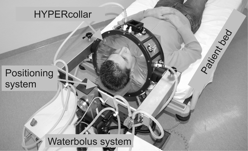
shows a picture of the HYPERcollar applicator system. Basically, the system consists of a normal patient bed and an applicator that can be moved over the head of the patient. After proper positioning, the waterbolus of the applicator is inflated with demineralized water and the twelve coaxial cables of the power system are connected.
Figure 1. Picture of the HYPERcollar applicator system. Both patient bed and positioning system (neck support) are used to position the patient. The coaxial cables, that are normally connected to the applicator, are not shown for visibility.
Power system
The power system delivers high-power radiofrequency (RF) signals with accurately controlled powers (±5%) and phases (±2°) to the applicator. First, a direct digital synthesis (DDS) system provides twelve coherent 433.92 MHz signals with independent phase shifts. These signals are amplified with PG70.1 50.2 power generators (SSB Electronic, Germany) up to 150 W. Circulators protect the amplifiers against reflected power and bi-directional couplers are used to measure both forward and reflected signals. Gains and phases are measured with twelve specially designed detectors Citation[14], which use one of the DDS system signals as a reference. Low-loss (<0.1 dB/m) coaxial cables are used to transfer the 433.92 MHz signal from the amplifiers to the C-connectors of the antennas.
HYPERcollar
The HYPERcollar consists of a transparent perspex cylinder (radius = 40 cm, height = 15 cm) covered with a fine conducting gauze forming the conducting backplanes required for the patch antennas. Twelve probe-fed patch antennas are mounted in two rings Citation[10] on the perspex cylinder. The distance between the centre planes of the two antenna rings is 6 cm. The patch antennas consist of a brass patch (28.2 mm × 7 mm) oriented in alignment with the patient-axis (z-axis) and connected, close to the short side, to the extending conducting rod of a C-female receptacle connector. A low - dielectric support is placed between backplane and patch for better robustness. Details of the dimensions of the patch can be found in Citation[12]. The entire applicator is attached to a movable trolley and can be rotated around the z-axis (patient-axis) and around the x-axis (left-right) for maximum positioning flexibility. An inflatable waterbolus is attached to the perspex cylinder for cooling of the skin and to enable an efficient transfer of the electromagnetic waves from the antennas into the patient.
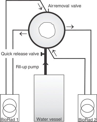
Waterbolus system
schematically shows the waterbolus system and a top view of the HYPERcollar: with cross-sections through the patient and waterbolus. The demineralised water in the waterbolus is circulated and temperature controlled by two E4850 refrigerated recirculators (Bio-Rad, Microscience Division). In- and outflow points are located at every other quadrant in order to obtain maximum temperature homogeneity in the waterbolus. A special pump is used to fill the bolus around the patient in approximately 30 s and the quick release valve can be used to empty the bolus in less than 5 s. A small valve at the top of the applicator is used to remove the air during the filling procedure. By closing all valves, a closed water system is obtained. The recirculators can also be attached to the water vessel to heat or cool this water to the desired water temperature prior to the treatment.
Figure 2. Schematic visualisation of the waterbolus system. Direction of flow within the tubes is indicated by the arrows.
Positioning system
Positioning of the patient in treatment position is carried out as follows. The patient, who is laying on the patient bed with the head over the edge of the bed, is positioned by moving the applicator as far as possible over the patient's head (∼l cm space between shoulders and applicator). Subsequently, the patient is moved to the desired position by altering the height of the patient-bed and subsequently the height of the neck support. To check the position of the patient according to planned positions, we verified the coordinates of the nose and jugular notch. Hereto we constructed a special device, including a water -gauge, that enables measurements using the origin of the applicator as a reference. The black square on top of the applicator (shown in ) is the holder of this device. After inflating the waterbolus, this positioning is verified in order to obtain the highest correspondence to the positions at which treatment planning was performed.
We assessed the level of comfort within the applicator in treatment position using five healthy volunteers, e.g. whether easily breathing remains possible. The volunteers were positioned within the applicator and subsequently the waterbolus was inflated with water. Volunteers remained in the applicator for approximately an hour.
Characterisation measurements
Compared to the laboratory prototype set-up Citation[13], the main differences are (1) the presence of a finite waterbolus, (2) a smaller distance between both antenna rings (6 cm), (3) a larger ring radius (40 cm) and (4) a new, more optimised, version of the patch antenna Citation[12]. For characterisation and quality assurance (QA) purposes we measured reflection and SAR patterns. The return loss Pr that is measured at the connectors of the HYPERcollar can be separated into the primary reflection of the antenna Pp.r. and the combined secondary contributions Ps.c. by cross coupling of the other antenna elements of the array, i.e. Pr = Pp.r. + Ps.c., where Ps.c. is the sum of the secondary contributions of the other eleven antennas. Dividing these contributions by the power that is directed towards each antenna, Pf, provides the respective reflection coefficients. Primary reflection characteristics were measured for various waterbolus temperatures to assess the temperature range in which operation is possible. The primary reflection coefficients were measured by attaching a network analyser (8751A, Agilent Technologies, USA) to the antennas and by using a centrally positioned cylindrical muscle equivalent phantom Citation[13]. We further assessed the SAR pattern of the HYPERcollar applicator within this cylindrical phantom by infra-red (IR) thermography, as in Citation[13]. In addition, we measured the (phase-dependent) return loss Pr for the phase settings corresponding to target centre point (TCP) steering in x (−60: 60 mm), y (−60: 60 mm) and z (−30: 30 mm) direction, in steps of 10 mm.
Treatment planning
In future, we will perform treatment planning for each patient since in our opinion this is mandatory for obtaining good heating profiles and to diminish the possibility of thermally related toxicity. Therefore, we illustrate such treatment planning for an example patient with a laryngeal tumour. Further, we illustrate the potential of large target volume heating by adding an artificial lymph node metastasis and analysing the SAR distributions within tumour and lymph node.
Patient model
The patient model was segmented from a CT-scan of a larynx patient that was made for radiotherapy treatment planning. Semi-automatic segmentation into different tissues was carried out by a medical doctor using a dedicated segmentation program Citation[15] (). The segmented tumour volume was 6.5 ml, which corresponds to the smallest target volume in Citation[9]. To investigate the possibilities of heating both primary tumour and lymph node metastasis, we also defined an artificial tumorous lymph node sphere (diameter = 4 cm, volume = 33.5 ml) and assigned properties of tumour to this volume. Because the CT-scan contained information of only 30 cm, we stretched the end slices of this model 5 cm to increase the height of the model to the outside of the waterbolus(), i.e. total height was 40 cm. Tissue properties at 433 MHz () for normal tissues were from Gabriel et al. Citation[16]. The properties of tumour tissue were obtained by using the average di-electric value of a number of tumours as measured by Joines et al. Citation[17].
Figure 3. Transparent anatomy visualisation in SEMCAD X. Bone tissue, the tumour and the artificial lymph node metastasis are non-transparently visualised.
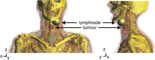
Table I. Tissue types and their dielectric properties at 433 MHz (μr = 1.0).
Applicator modelling
We predicted the SAR distributions in the clinical prototype applicator using SEMCAD X (Citation[18]; Schmid & Partner Engineering AG, Switzerland). Settings for the FDTD modelling of the HYPERcollar were equal as in Citation[13], in which we verified the accuracy of the model for a laboratory prototype. The grid was aligned to the antennas and automatically refined down to 0.5 mm at the antennas for maximum accuracy (4), which resulted in a total amount of 7.8 million voxels.
SAR optimisation
Two methods of SAR optimisation were applied and their suitability was compared. The TCP method provides a fast way of calculating the phases without the requirement of treatment planning. The second method (“Optimised SAR”) requires full treatment planning but includes information of the actual geometry (applicator and patient) in the optimisation.
TCP settings The first method of SAR steering follows the method that is used in the BSD2000 Sigma-60 system Citation[13]. For each antenna, we analytically calculated the required phase delays, using the difference in wave velocity in muscle and water, such that maximum interference occurs at the desired TCP in a cylindrical phantom. These phases are subsequently used in the setup with patient anatomy and HYPERcollar. The amplitudes are always equal for all antennas.
Optimized SAR For the second method of SAR steering, we optimised amplitudes and phases by using the optimisation procedure of Kohler et al. Citation[19] to maximise optimisation parameter I:in which ti is the i-th target region from a total of Ni target regions and nj is the j-th normal tissue region from Nj normal tissue regions. The weight of the total amount of SAR in a certain region can be selectively increased or decreased respectively by adapting the weight factors Si and Sj. By choosing appropriate weight factors, it is possible to adjust the SAR patterns such that all target regions are sufficiently covered by the preferred iso-SAR contour. This is still a manual iterative process since we have no tool yet to optimise iso-SAR coverage.
Results
Comfort of the applicator
Comfort tests with healthy volunteers have revealed that the applicator provides sufficient comfort to maintain in treatment position for an hour: which will be the hyperthermia treatment duration for H&N patients in our centre. We observed no breathing problems due to waterbolus pressure at the trachea, provided that the waterbolus was filled carefully. A special neck support has been constructed since the comfort tests revealed that such a support would provide more stability during filling of the waterbolus and would increase the reproducibility of the positioning.
Characterisation measurements
Reflection characteristics
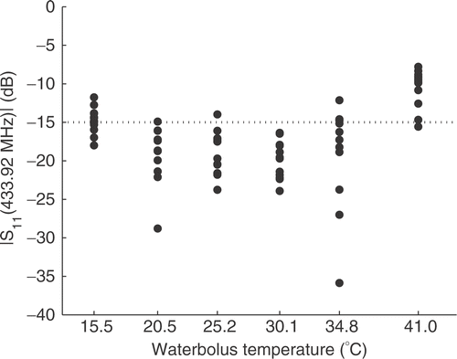
In Paulides et al. Citation[12] we have defined the expected clinically relevant range of waterbolus temperatures, i.e. between 20 and 30°C. provides the primary reflection coefficients measured using the NWA at each antenna, for waterbolus temperatures within and outside this range. The figure shows a temperature dependence, related to the change of the permittivity of the water underneath the patch, that is in agreement with the findings in the previous study Citation[12]. The primary reflection of almost all antennas is below −15 dB (3%) for temperatures between 20 and 30°C. Releasing this threshold to −10 dB (10%), the applicable temperature range can even be increased to between 15 and 35°C, while the average reflection coefficient remains under −14 dB.
Figure 4. The HYPERcollar applicator and the patient within. The waterbolus and the upper head model extension are not visualised to show some patch antennas. (a): Solid model (b): Grid implementation.
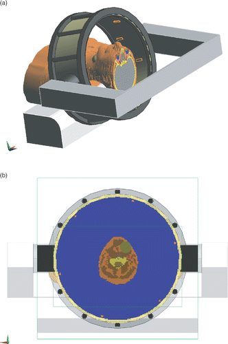
Figure 5. Primary reflection coefficient (Pp·r·/Pf in dB) at 433.92MHz for different water-bolus temperatures and all 12 antennas. A cylindrical muscle equivalent phantom was used to mimic the patient's neck.
summarises the statistics of the measured return loss coefficient Pr/Pf for the different phase settings described in section “Characterisation measurements”. This table shows that, due to primary reflection and secondary contributions, on average 6% return loss can be expected during treatments, with peaks up to around 31%. The return loss values are found to be highest for the most ventral antennas (1_1 and 2_1). This is due to the waterbolus that bulges out more in dorsal (−y) locations than in ventral (+y) locations. Therefore, the water-air transitions are the closest to the antennas and air inclusions, due to the folds in the waterbolus, are the largest.
Table II. Statistics of the measured return loss coefficient Pr/Pf (%) at every antenna (e.g., 12 is the second antenna of the first antenna ring) for TCP-steering settings.
Measured SAR distribution
By IR measurements we have established that a central focus can be obtained in the cylindrical muscle equivalent phantom. shows the measured SAR pattern for central steering settings, i.e. TCP=(0, 0, 0). The figure shows a central focus very close (5 mm difference) to the desired focus position. The small asymmetry that can be observed in the x-direction falls within the assumed accuracy of the measurement.
Figure 6. SAR distribution (mW/kg) at the midplane (y = 0) within the, 11.6 cm diameter, cylindrical muscle equivalent phantom for central phase steering (φi = 0, i = 1, … , 12) and a combined total input power of 1 W. The midplanes of the two antenna rings are located at z = −30 mm and z = 30 mm.
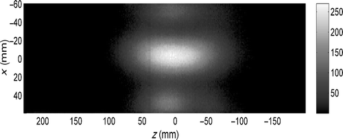
The length L50% of the focus for central steering is around 90 mm and its width W50% is 35 mm (). By TCP based phase adjustments, the focus can be steered to maximum 50 mm (x-direction), 50 mm (y-direction) and 30 mm (z-direction) from the origin (central steering) in the homogeneous muscle equivalent phantom. shows that the dimensions of the focus change for steering in the x (and y) direction but remain equal for steering in the z-direction, i.e. the focuslength varies between 88 and 103 mm 5 and the focuswidth between 35 and 48 mm.
Table III. SAR steering (direction and TCP setting (x, y, z)) and corresponding focus-size (length L50% and width W50% of the 50% iso-SAR contour) parameters for the IR thermog-raphy measurements. All dimensions are in mm.
Predicted SAR in a patient model
SAR distributions were evaluated by using the 1 g averaged Spatial Peak SAR [IEEE-1529] to remove high SAR values due to the staircase approximation of FDTD. For the SAR predictions corresponding to the different SAR steering settings, we show the 25% iso-SAR volume and cumulative SAR-Volume histograms. Rather than normalising the SAR distributions to the maximum value we calculated the SAR for 1 W total input power so absolute SAR values can be obtained by multiplication with the total input power of all combined antennas. Since we used a highly detailed description of the complete patch antennas, including all their dimensions, and we consider only the real radiated power, we consider these results to be predictive for the actual SAR.
25% iso-SAR volumes
The possibilities of TCP-based phase-steering and optimised phase and amplitude settings for this patient are shown in . The figure shows the 25% iso-SAR volume on top of the tumour, lymph node and bony structures. shows the iso-SAR volumes corresponding to TCP steering with the TCP in the middle between tumour and lymph node (“TCP @ tumour + lymph node”). This results in SAR coverage at the lymph node but the tumour is not covered. Therefore we adjusted the point of focus towards the centre of the tumour. The corresponding SAR is shown in (“TCP @ tumour”). For these phase settings a much better coverage of the tumour and an almost equal situation for the lymph node is obtained but at the cost of (1) a hotspot at the shoulder and (2) a large region of high SAR values at the back of the neck region. shows the iso-SAR volumes for optimised settings with equal weight factors for all tissues (“Optimised settings”).
Figure 7. 25% iso-SAR volumes, shown in grey, for the four investigated settings. The figure further shows the bony structures (yellow) and the tumour (red) and artificial lymph node sphere (dark red).
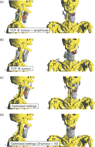
The figures show selective SAR coverage of the lymph node and limited coverage of the more difficult to heat central tumour. Therefore we increased the weight factor of the tumour (Stumour) to 10 in order to obtain a better SAR coverage of both tumour and lymph node, which is shown in . This figure shows that the change in priority led to coverage of all of the tumour and almost all of the lymph node by the 25% iso-SAR volume.
Cumulative SAR-Volume histograms
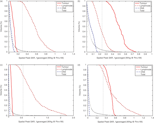
To show the more subtle differences in the SAR patterns of all settings, we show the cumulative SAR histograms in . Cumulative histograms specify the percentage of a certain volume that receives a specified SAR “dose”. Histogram curves are shown for tumour, lymph node, central nerve system (CNS: myelum and brains), and total head volume. shows that the SAR level at the CNS is under the 25% iso-SAR value for all settings, and that high SAR values are obtained in the two target regions. and show the histograms corresponding to TCP steering. When the TCP is between lymph node and tumour, the SAR values in the lymph node are over 25% but the tumour is not covered. When the point of focus is adjusted to the tumour, the SAR values at the tumour are much higher but at the cost of lower SAR values in the lymph node. and () show the histograms corresponding to optimized settings. Compared to TCP settings, these settings result in higher SAR values in the lymph node and, as a result, relatively lower SAR values in CNS. The SAR values in the lymph node volume, however, are much higher than the SAR values in tumour for equal selectivity settings (Stumour = Slymphnode = 1). The SAR coverage of the tumour can be effectively improved by a ten-fold increase of the tumour volume weight factors, due to lower values in the lymph node and higher values in the tumour. Therefore a much more homogeneous SAR coverage of the entire target region is obtained with these settings, i.e. over 85% of all SAR values in both target regions are above the 25% iso-SAR value.
Figure 8. Cumulative SAR-Volume histograms for the four investigated settings using 1 g-averaged Spatial Peak SAR values. The 25% iso-SAR value (25% of the maximum value in the entire patient model) is indicated by the straight dotted line. (a) TCP@ tumour + lymphnode, (b) TCP @ tumor, (c) Optimised settings Stumors =1, Slymphnode = 1 and (d) Optimised settings Stumors = 10, Slymphnodee = 1.
Discussion
Comfort tests with healthy volunteers have revealed that the HYPERcollar provides sufficient stability to remain in treatment position for an hour. Further, we observed no breathing problems due to waterbolus pressure at the trachea, provided that the waterbolus was filled carefully. However, we anticipate that comfort may be lower for patients with a combination of a short neck and high shoulders. Further, we still need to assess if completion of an entire session is possible for the patients that are generally older and may suffer from severely damaged skins. In a clinical feasibility study, we will investigate whether these items of concern lead to major problems. In that study we will also investigate whether heating or comfort problems can be solved by a changed applicator design or can be converted into exclusion criteria for selected groups of patients.
The primary reflection coefficients (Pp.r.) of, early versions of, the twelve patch antennas in the laboratory prototype were all beneath 10% (−10 dB) for waterbolus temperatures at 23 and 25°C Citation[13]. The newly designed patch antenna Citation[12] is found to perform better, with a maximum primary reflection of 16% (−12 dB) for temperatures between 15 and 35°C. However, when taking into account the contributions of other antennas we find a total reflected power of maximum 31% and 6% on average, for measurements using a variety of phase settings and with the water temperature at 25°C. Since we expect that cross-coupling is approximately equal for different temperatures, we assume that the minor increase in primary reflection results in acceptable return loss values at waterbolus temperatures in the range of 15 to 35°C. In the clinical applicator, we installed circulators that guide the remaining return loss towards a matched load and, since the amplifiers can deliver sufficient power, we expect no influence of these return losses on the treatment.
In an earlier study, using a laboratory prototype, we found a central 50% iso-SAR focus of 35 mm (±3 mm) in diameter and around 100 mm (±15 mm) in length Citation[13]. However, based on a simultaneously performed parameter study Citation[10], we decreased the distance between the two antenna rings from 8 to 6 cm and increased the antenna ring radius) from 30 to 40 cm for the HYPERcollar applicator. As expected, the width of the 50% iso-SAR focus is equal for prototype and HYPERcollar. The length of this focus, however, shows a minor decrease to 90 mm while a small increase was expected. The decrease in focus length is caused by the finite length of waterbolus introducing water–air transitions that were not taken into account in the prototype setup. We expect that the waterbolus will conform better to a patient anatomy, which has a larger average diameter and more concave shape, and waterbolus edges will therefore be further away from the region of interest. As a result, the influence of the waterbolus on the SAR pattern in a patient is expected to be lower than the influence on the phantom. Nevertheless, the waterbolus shape should resemble the actual shape as close as possible for obtaining a good match between the predictions and reality.
In this study we calculated the SAR for 1 W total input power so that absolute SAR values were obtained. These SAR values are considered predictive for the actual SAR since we accurately model the entire antenna. In an earlier study, we have shown that using such a model the impedance of the antenna can accurately be predicted using SEMCAD X Citation[12]. Since the field pattern is generally a less sensitive parameter than the impedance for such a patch antenna setup, we assume a high predictability also for the electric-field pattern. In that study Citation[12], however, we modelled the complete connector and the transmission line while in the current study we used the commonly accepted approach to apply a voltage source at the gap between the conducting backplane and the rod of the patch antenna. By comparing these ways of modelling, we found no differences in electric field pattern and a scalar difference in power of around 15%.
The possibility of heating in the neck region has been investigated by performing treatment planning on an example patient with a laryngeal tumour and an artificial lymph node sphere. The tumour of 6.52 ml corresponds to the smallest target volume in Citation[9] and may be smaller than the general tumour size of patients suffering from advanced tumours. By adding a relatively large lymph node region at the periphery of the neck we obtained a more irregular target region that is therefore much more difficult to heat. It can be seen as an extreme case since SAR coverage was required for a maximum distance of 8.3 cm, while it was simultaneously attempted to achieve a low SAR level in between at the healthy tissues. A high SAR at a large target volume means sufficient defocusing possibilities and a low SAR in between the target volumes requires additional degrees of freedom. We found that selective focusing at the target area can be obtained in the transversal plane but in the direction of the patient axis (z-axis) this focus is somewhat large for target-specific heating. The tumour alignment in the transversal plane is more important since in this planes the critical tissues are nearby. Currently we are performing a clinical feasibility study in which we are investigating the feasibility of selectively heating a target region in the H&N region with the HYPERcollar applicator system.
When evaluating the obtained predictions, we faced the common problem of the inability to define the quality of a hyperthermia treatment Citation[20]. For superficial hyperthermia the effective field size (EFS; the area enclosed by the 50% iso-SAR contour) and penetration depth as defined in the ESHO quality guidelines Citation[21] provide a general solution for single applicators and SAR distributions in semi-homogeneous (e.g. layered) phantoms. As a prognostic factor for treatment planning in patient anatomies, Lee et al. Citation[22] found for superficial hyperthermia treatment of 196 patients that 25% iso-SAR coverage was superior to 50% iso-SAR coverage. Therefore, we have focused on the 50% iso-SAR contour for phantom measurements while maximising the 25% iso-SAR coverage at treatment planning.
Thermal predictions were not carried out since: (1) the blood perfusion rate of H&N tumours can vary up to 80-fold Citation[23] and (2) large differences in blood perfusion rate have been measured for increasing temperatures (muscle: 0.45–40 kg/m3/s) Citation[24]. A separate analysis containing a thorough sensitivity analysis is required to shine some light on the predictive value of the obtained temperature distributions. Since our initial aim has always been to design an applicator that provides possibilities to obtain a good SAR coverage of the target volume, we have omitted thermal calculations.
Conclusions
The HYPERcollar, a newly constructed H&N HT applicator has been presented and its features has been explained. By tests with healthy volunteers, we established that the applicator is sufficiently comfortable for a healthy person to be in treatment position for one hour.
From the characterisation measurements, we conclude that the reflections remain sufficiently low within a waterbolus temperature range of 15–35°C. By IR thermography we measured a central 50% iso-SAR focus of around 90 mm in axial and 35 mm in radial direction in a muscle equivalent phantom.
Treatment planning showed that the SAR pattern can be shaped such that simultaneous 25% iso-SAR coverage of a deep-seated tumour and a superficial lymph node is possible for a challenging case. In future research, by applying heat sessions to patients, we will verify the possibility of deep heating in the H&N area.
Acknowledgements
This work was financially supported by the Dutch Cancer Society, grant: DDHK 2003-2855. The authors further would like to thank B. van Toorn for manufacturing the clinical applicator prototype.
Related Research Data
References
- El-Sayed S, Nelson N. Adjuvant and adjunctive chemotherapy in the management of squamous cell carcinoma of the head and neck region: A meta-analysis of prospective and randomized trials. J Clin Oncol 1996; 14: 838–847
- Pignon JP, Bourhis J, Domenge C, Designe L. Chemotherapy added to locoregional treatment for head and neck squamous-cel carcinoma: Three meta-analyses of updated individual data. Lancet 2000; 355: 949–955
- Trotti A. Toxicity in head and neck cancer: A review of trends and issues. Int J Radiation Oncology Biol Phys 2000; 47: 1–12
- Valdagni R, Liu F-F, Kapp S. Important prognostic factors influencing outcome of combined radiation and hyperthermia. Int J Radiat Oncol Biol Phys 1988; 15: 959–972
- Valdagni R, Amichetti M. Report of long-term follow-up in a randomized trial comparing radiation therapy and radiation therapy plus hyperthermia to metastatic lymphnodes in stage IV head and neck patients. Int J Radiat Oncol Biol Phys 1993; 28: 163–169
- Stauffer PR. Evolving technology for thermal therapy of cancer. Int J Hyperthermia 2005; 21: 731–744
- Jouvie F, Bolomey JC, Gaboriaud G. Discussion of the capabilities of microwave phased arrays for hyperthermia treatment of neck tumours. IEEE Trans Micr Theor Tech 1986; 34: 495–501
- Magin RL, Peterson AF. Noninvasive microwave phased arrays for local hyperthermia: A review. Int J Hyperthermia 1989; 5: 429–450
- Paulides MM, Vossen SHJA, Zwamborn APM, Van Rhoon GC. Theoretical investigation into the feasibility to deposit RF energy centrally in the head and neck region. Int J Rad Onc Biol Phys 2005; 63: 634–642
- Paulides MM, Bakker JF, Zwamborn APM, Van Rhoon GC. A head and neck hyperthermia applicator: Theoretical antenna array design. Int J Hyperthermia 2007; 23: 59–67
- Paulides MM, Wielheesen DHM, Van der Zee J, Van Rhoon GC. Assessment of the local SAR distortion by major anatomical structures in a cylindrical neck phantom. Int J Hyperthermia, (in press)
- Paulides MM, Bakker JF, Chavannes N, Van Rhoon GC. “A patch antenna design for a phased-array head and neck hyperthermia applicator,”. IEEE Trans. Biom. Eng, in press
- Paulides MM, Bakker JF, Van Rhoon GC. A head and neck hyperthermia applicator: Experimental phantom verification and FDTD model. Int J Rad Onc Biol Phys 2007; 68: 612–620
- Bakker JF, Paulides MM, van Rhoon GC, Schippers H, Ter Meer TA. Development of a gain & phase detector for a hyperthermia applicator. In Proceedings of the joint 9th International Conference on Electromagnetics in Advanced Applications (ICEAA ’05) and 11th European Electromagnetic Structures Conference (EESC ’05). TorinoItaly 2005; 209–212, ISBN 88-8202-094-0
- Neufeld E, Samaras T, Chavannes N, Kuster N. ‘Robust, highly detailed, medical image segmentation,’ in the Book of Abstracts of the 22nd Annual Meeting of the ESHO. Graz, Austria (ESHO-05) 2005; 56–57
- Gabriel S, Lau RW, Gabriel C. The dielectric properties of biological tissues III: Parametric models for the dielectric spectrum of tissues. Phys Med Biol 1996; 41: 2271–2293
- Joines WT, Zhang Y, Li C C, Jirtle RL. The measured electrical properties of normal and malignant human tissues from 50 to 900 MHz. Med Phys 1994; 21: 547–550
- SEMCAD: The Simulation platform for EMC, Antenna Design and Dosimetry Schmid & Partner Engineering AG, http://www.speag.com
- Kohler T, Maass P, Wust P, Seebass M. A fast algorithm to find optimal controls of multiantenna applicators in regional hyperthermia. Phys Med Biol 2001; 46: 2503–2514
- Oleson JR. If we cant define the quality, can we assure it? Int J Radiat Oncol Biol Phys 1989; 16: 879
- Lagendijk JJW, Van Rhoon GC, Hornsleth SN, Wust P, De Leeuw AC, Schneider CJ, Van Dijk JD, Van Der Zee J, Van Heek-Romanowski R, et al. ESHO quality assurance guidelines for regional hyperthermia. Int J Hyperthermia 1998; 14: 125–133
- Lee HK, Antell AG, Perez CA, Straube WL, Ramachandran G, Myerson RJ, Emami B, Molmenti EP, Buckner A, Lockett MA. Superficial hyperthermia and irradiation for recurrent breast carcinoma of the chest wall: Prognostic factors in 196 tumors. Int J Radiat Oncol Biol Phys 1998; 40: 365–375
- Vaupel P, Höckel M. Blood supply, oxygenation status and metabolic micromilieu of breast cancers: Characterization and therapeutic relevance (Review). Int J Oncol 2000; 17: 869–879
- Lang J, Erdmann B, Seebass M. Impact of nonlinear heat transfer on temperature control in regional hyperthermia. IEEE Trans Biomed Eng 1999; 46: 1129–1138